RESEARCH OUTPUTS / RÉSULTATS DE RECHERCHE
Author(s) - Auteur(s) :
Publication date - Date de publication :
Permanent link - Permalien :
Rights / License - Licence de droit d’auteur :
Bibliothèque Universitaire Moretus Plantin
Institutional Repository - Research Portal
Dépôt Institutionnel - Portail de la Recherche
researchportal.unamur.be
University of Namur
Coiled carbon nanotube structures with supraunitary nonhexagonal to hexagonal ring
ratio
Biró, László P.; Márk, Géza I.; Koós, Antal A.; B.Nagy, János; Lambin, Philippe
Published in:Physical Review B - Condensed Matter and Materials Physics
DOI:
10.1103/PhysRevB.66.165405
Publication date:
2002
Document Version
Publisher's PDF, also known as Version of record Link to publication
Citation for pulished version (HARVARD):
Biró, LP, Márk, GI, Koós, AA, B.Nagy, J & Lambin, P 2002, 'Coiled carbon nanotube structures with supraunitary nonhexagonal to hexagonal ring ratio', Physical Review B - Condensed Matter and Materials Physics, vol. 66, no. 16, pp. 1-6. https://doi.org/10.1103/PhysRevB.66.165405
General rights
Copyright and moral rights for the publications made accessible in the public portal are retained by the authors and/or other copyright owners and it is a condition of accessing publications that users recognise and abide by the legal requirements associated with these rights. • Users may download and print one copy of any publication from the public portal for the purpose of private study or research. • You may not further distribute the material or use it for any profit-making activity or commercial gain
• You may freely distribute the URL identifying the publication in the public portal ?
Take down policy
If you believe that this document breaches copyright please contact us providing details, and we will remove access to the work immediately and investigate your claim.
to 4:3. In the coiled nanotubes produced actually by catalytic chemical vapor deposition, it is not impossible that such a high concentration of nonhexagonal units in the nanotube structure be the result of a fast kinetic leading to metastable states that cannot anneal out due to the low growth temperatures used.
DOI: 10.1103/PhysRevB.66.165405 PACS number共s兲: 61.46.⫹w, 68.37.Ef, 45.10.Db, 81.15.Gh
I. INTRODUCTION
Since the first observation by Iijima of multiwall carbon nanotubes共MWCNT’s兲 a decade ago,1an explosive develop-ment has taken place in the physics and chemistry of these new materials. The three main directions envisaged right now for practical applications of carbon nanotubes are 共a兲 nanoelectronics, 共b兲 field emission based devices and flat panel displays, and 共c兲 carbon nanotube reinforced compos-ite materials. The recent months brought impressive break-throughs towards practical applications in nanoelectronics: logic gates assembled from nanowires2and carbon nanotube based logic circuits,3 and in field emission devices: the achievement of a lighting element with cylindrical geometry.4
One of the major problems in producing carbon nanotube reinforced composites, which fully exploit the very high Young’s modulus of carbon nanotubes, arises from the weak interaction of the straight carbon nanotubes, either single wall carbon nanotubes 共SWCNT’s兲 or MWCNT’s, with the matrix in which they are incorporated.5 As a consequence, the nanotubes move in the matrix similar to a sword in the scabbard. Chemical functionalization and covalent bonding through the functional groups between the CNT and the ma-trix may help in the case of MWCNT’s. However, in the case of SWCNT’s, the large number of functional groups needed makes that the carbon network is weakened in many points, so that the excellent mechanical properties of the SWCNT’s may be seriously affected. A more elegant solution could be to use coiled multiwall,6single-wall,7,8or Y-branched carbon nanotubes8 –11 for reinforcing composite materials. As re-cently shown, the mechanical properties of the multiwall coiled carbon nanotubes are comparable to those of straight MWCNT’s.12
The toroidal,13 coiled,14,15 and Y-branched16 –18 carbon nanotubes were predicted theoretically soon after the discov-ery of the straight nanotubes. All these structures are based on the insertion of nonhexagonal共n-Hx兲 defects in the seam-less hexagonal共Hx兲 network. In particular, the models of the
regular helical coils of CNT’s are based on a very specific arrangement of pentagons共P兲 and heptagons 共H兲 in a perfect Hx lattice.15,19 If the regular arrangement is perturbed by misplacing one single n-Hx ring, the structure will not be a regular coil any more.19A general characteristic of the above coil models is that the ratio n-Hx to Hx is far less than unity. For example, in the case of a single Dunlap knee connecting
共3,3兲 to 共6,0兲 nanotubes with a bend of 30° 共Ref. 14, Fig. 2兲
when the smallest possible number of Hx rings is used, the ratio n-Hx/Hx is 0.125. A torus can be built by joining to-gether 12 such knees. C540 is the smallest torus made of connected 共6,0兲 and 共3,3兲 segments14 giving n-Hx/Hx
⫽0.098. Larger torus diameter can be produced by adding
six rows of zig-zag and six rows of armchair hexagons to increase the distance between the knees, this will yield an even lower n-Hx/Hx ratio. The toroidal structures proposed by Ihara and co-workers contain ten pentagons and ten heptagons.13This yields a ratio of 0.125 for a C360type torus. On the experimental side, C60, the first carbon cage
pro-duced, has a much higher n-Hx/Hx ratio: 0.6. It is worth pointing out that the first MWCNT’s共n-Hx/Hx tends to zero兲 have been observed in C60-soot,1i.e., within the same experi-ment carbon nanostructures with quite different n-Hx/Hx ra-tios can be synthesized. Later on, the conditions were opti-mized for the preferential production of straight CNT’s.
Recently new structures have been proposed for building straight carbon nanotubes20 and tori21 with n-Hx/Hx ratio over unity. It is worth mentioning that Terrones and co-workers20 proposed tubular structures built of only pen-tagonal and heppen-tagonal rings, too. These structures are ther-modynamically stable. In the present paper we examine the possibility of building regular, helically coiled carbon nano-tubes with n-Hx/Hx ratio higher than unity.
II. PLANAR CONSTRUCTIONS
The general rule we apply throughout this paper is that the polygons, which we use in all the planar constructions, are regular ones, i.e., their edges have all the same length, and
the edges of all pentagons, hexagons, and heptagons are identical.
A. The Azulenoid stripe
When one intends to construct a planar structure which will yield a regularly coiled carbon nanotube, in some re-spect, this is the reverse of the task the geographers were facing when trying to map the spherical Earth onto a plane. Their solution, i.e., introducing regular cuts in the polar re-gions, can be adapted to the curved carbon nanostructures, too. This operation, if performed on the azulenoid torus pro-posed by La´szlo´ and Rassat,21will yield a construction simi-lar to the one in Fig. 1. Depending on the kind of cuts used in the planar structure, the same number of ‘‘azulene’’ units may generate a straight tube, or a torus共actually half a torus if 11 units are used as in Fig. 1, the complete torus requires 22 azulenes兲. The construction is made in the following way: after closing the adjacent cuts, one atom is eliminated where two would have to occupy the same site. Than the upper edge of the crumpled sheet generated in this way is joined to the lower one, again eliminating the doubled atoms. In the case of the torus, the convex tips of the heptagons of upper
共lower兲 edge match the concavities produced between two
adjacent heptagons of the opposite edge. For the straight tube, a left or right shear has to be applied to the rolled-up structure. The structure obtained by using this latter con-struction remains straight, unlike the one generated from the former, which naturally circle and eventually crops itself when the number of units is large enough.
A somewhat similar construction method, yielding a trun-cated icosahedron, similar to the C60, was proposed around
the year 1500 by Du¨rer 关Ref. 22, Fig. 1.2兴. The truncated icosahedron was constructed in a similar way as discussed in Fig. 1, folding up a sheet of cardboard.
B. The 57À1Ã6 stripe
The azulenoid structures discussed in the previous section are very unlikely to exist in the real world. The stress built in the C-C bond by rolling up the stripes shown in Fig. 1 to
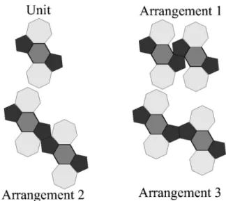
produce closed structures is very high due to the large cur-vature. To overcome this problem, one has to reduce the stress value by increasing the distance between the edges of the stripe which will be joined together, i.e., the number of polygons in a direction transversal to the stripe axis has to be increased. One way to achieve this widening of the stripe is to insert hexagons in the azulenoid structure. When a hexa-gon is added to an azulenelike arrangement of carbon atoms, the most compact arrangement is achieved when the P, Hx, and H rings all share common edges. The structure built according to the above rule is shown in Fig. 2 The unit of Fig. 2 can be combined in various ways to produce stripes; some of these are exemplified in the figure. In this paper we will investigate the most compact of these stripes, the ar-rangement labeled 1, and the further constructions that can be generated from it. The unit shown in Fig. 2 has n-Hx/Hx⫽4. Joining repeatedly units having the arrange-ment 1 yields a stripe similar to the one shown in Fig. 3. It can easily be seen that, when closing the cuts between the neighboring polygons of the stripe, a curved surface will be generated. The long edges of this surface can be joined in various ways to form closed 3D structures. These will be discussed in detail in Sec. III.
FIG. 1. Azulenoid stripes, both containing 11 units, one giving a straight tube, the other a half torus关21兴, respectively. The character of the generated 3D object depends on the arrangement of the poly-gons.
FIG. 2. 57⫺1⫻6 unit generated from two azulenoid units sepa-rated by a hexagon in a way that the P, Hx, and H share common edges. Three possible ways of assembling the 57⫺1⫻6 unit in stripes.
FIG. 3. Stripe of 57⫺1⫻6 units according to the arrangement 1 from Fig. 2. The closed stripe will be generated by closing the white gaps in a way that A⬙will be fused with B⬘, B⬙with C⬘, 1⬙with 2⬘, 2⬙with 3⬘, ... .
BIRO´ , MA´RK, KOO´S, B.NAGY, AND LAMBIN PHYSICAL REVIEW B 66, 165405 共2002兲
C. The 57À2Ã6 and the 57À3Ã6 stripes
The insertion of one single hexagon produces only a mod-erate widening of the stripe. A possible way to continue the widening in a regular way is to insert two, three, or more hexagons. The stripes generated in this way by inserting two (57⫺2⫻6) and three (57⫺3⫻6) hexagons are shown in Fig. 4. The n-Hx/Hx ratio is 2 for the stripe with two Hx, and 1.33 for the stripe with three Hx. Closing the cuts in these stripes, in a similar way as already discussed in the case of a 57⫺1⫻6 stripe, will generate curved surfaces. These curved sheets can be closed into 3D, tubular structures of different conformations depending on the closing rules used.
III. 3D STRUCTURES
The planar constructions shown in Figs. 3 and 4 were closed using the desktop molecular modeler 共DTMM兲
pro-gram, the resulting construction was optimized by minimiz-ing the bond energies. A second type of optimization was performed by minimization of the Tersoff-Brenner potential,23starting from the atomic coordinates generated by
DTMM or from geometrically calculated ones. In the optimi-zation processes, the coordination table of the atoms as de-fined by the starting stripe were kept fixed. The elimination of the white gaps present in the stripe 57⫺1⫻6, by closing side by side the neighboring polygons, as discussed above, yields closed surfaces an example of which is shown in Fig. 5. The surface in Fig. 5共a兲 was generated byDTMM, while the one in Fig. 5共b兲 was optimized with the Tersoff-Brenner po-tential. The two shapes are practically identical. The bowl shaped surface can be transformed into a three-dimensional
共3D兲 closed object 共neglecting the two ends兲 using one of the
closing rules given in Table I.
It is somewhat difficult to give an unambiguous nomen-clature for the resulting curved objects. The name ‘‘coil’’ is used for a 3D object which viewed along its coiling axis is seen as a ‘‘circle,’’ the name ‘‘curled tube’’ is used for a 3D object which viewed along its curling axis is not seen as a circle, but like an undulated line. For example the object
shown in Fig. 2 of Ref. 7 will be called a coil, while the
FIG. 4. Stripes 57⫺2⫻6 and 57⫺3⫻6 generated in a similar way as the one shown in Fig. 3. The same rules apply for obtaining a closed stripe, similar to that in Fig. 3.
FIG. 5. Bowl-like stripes generated from the stripe of Fig. 3.共a兲 Structure generated with DTMM, darker shades denote the interior surface of the structure; 共b兲 structure generated using the Tersoff-Brenner potential.
TABLE I. Closing rules used for transforming the stripes into closed 3D objects.
Stripe or sheet Closing rule 3D structure
57⫺1⫻6 1⬘to A Coil right hand
1 to A⬙ 共Fig. 6兲 1⬘to B Curled tube 1 to B⬙ 1⬘to C Curled tube 1 to C⬙ 57⫺2⫻6 1⬘to A Curled tube 1 to A⬙
1⬘to B Coil left hand
1 to B⬙
1⬘to C Coil right hand
1 to C⬙
57⫺3⫻6 1⬘to A Curled tube
1 to A⬙
1⬘to B Curled tube
1 to B⬙
1⬘to C Coil right hand
1 to C⬙ 关Fig. 7共a兲兴
2⫻(57⫺1⫻6) 1⬘(II) to C(I) Double helix 1(II) to C⬙(I) 关Fig. 8共c兲 and 8共d兲兴
regularly undulated object seen in Fig. 1 of Ref. 24 will be called a curled tube.
When using the particular closing rule 1
⬘
to A; 1 to A⬙
, for the bowl shaped objects shown in Fig. 5, one obtains a coiled tube. All other closing rules produce various curled tubes with increasing diameter as the distance between the particular edge segments共in the original planar construction polygon edges兲 involved in specifying the closing rule, the one denoted by letters (XX⬙
) and that denoted by numerals (n⬘
n) increases. The distance measured between these two edge segments will turn after full closing in a circle con-tained in the tube surface, normal to the local 共coiled or curled兲 axis, so that the distance between the edge segments divided by will give the diameter of the tube. The coiled tube obtained from the stripe 57⫺1⫻6 using DTMM is shown in Fig. 6共a兲, while the coiled tube produced with the Tersoff-Brenner optimization is shown in Fig. 6共b兲. In a simi-lar way one can generate coils from the stripes 57⫺2⫻6 and the 57⫺3⫻6, too. The closing rules, which yield coils, are indicated in Table I. Each coil has left-handed and right-handed enantiomers.By contrast with the earlier coil models having n-Hx/Hx ring ratios well below unity, the structure of the coils con-structed here is remarkably robust. If defects are inserted, the shape of the coil suffers from minor modifications only. This is illustrated in Fig. 7 where several 57⫺3⫻6 type coils are shown: in 共a兲 a defect free coil, in 共b兲 a coil in which there are carbon atoms which have only two bonding neighbors, and in共c兲 a structure in which these ill bonded carbons 共two-fold coordinated carbons兲 have been fused with their regu-larly bonded neighbors, as a result, the hexagons were trans-formed in pentagons and the heptagons in hexagons in agreement with Euler’s theorem for a perfect threefold coor-dinated network. As seen in the figure, the defects produced only a minor lengthening of the structure, while the overall shape suffered only from insignificant alterations.
It is worth mentioning that by joining several stripes, such as the ones shown in Figs. 3 and 4, one can generate sheets. These sheets are not planar like in the case of graphite. After
optimization, the planes have a crumpled shape, such a sheet constituted of 2⫻(8⫻关57⫺1⫻6兴 units is shown in Fig. 8共a兲. On the other hand, if an average curvature is applied initially to the sheet, it rolls up and a structure resembling two fused bowls is produced, Fig. 8共b兲. This is not an unre-alistic starting condition given that the coiled tubes are ob-served in catalytically grown nanotubes only. The formation of carbon rings and sheet takes place not in the free space, but nucleate on the curved surface of a catalytic particle. Generally speaking, these can be regarded as having a spherical shape, i.e., they impose an average curvature to the sheet in formation. Energy calculations for the two structures shown in Figs. 8共a兲 and 8共b兲 yield values that differ by less than 0.1 eV/atom.
Applying similar closing rules to the sheets like the ones used for the stripes, one may generate curved structures of higher complexity. In particular, using the closing rule 1
⬘
(II) to C共I兲; 1共II兲 to C⬙
(I) where the roman numerals in brackets indicate stripe one共upper兲 and stripe two 共lower兲 of the sheet composed of two stripes one may generate a regular double helix, such as the one shown in Fig. 8共c兲. In Fig. 8共d兲 an experimental, scanning tunneling microscope 共STM兲 image is shown, in which such a double helix is seen extended over several hundreds of nanometers. If the structure would be built of two, independent, but intercoiled nanotubes, the STM topography should be different due to the particular tunneling conditions at the points where the two tubes cross each other under the STM tip. Two defect regions are indi-cated by white arrows, one may note that the structure has a ‘‘self-correcting’’ capacity, it continues defect-free growth after a short disturbed region. Similar looking double and triple helixes were reported recently as being produced by iron coated indium-tin oxide catalytic particles.25FIG. 6. Coil generated from the bowl-like surface of Fig. 5 by applying the closing rule 1⬘ to A and 1 to A⬙. 共a兲 Coil generated withDTMM;共b兲 coil generated with the Tersoff-Brenner potential.
FIG. 7. Coil generated starting from a 57⫺3⫻6 sheet using
DTMM. 共a兲 Defect free coil; 共b兲 coil with three ill bonded carbon atoms, the ill bonded atoms are shown as dark spheres;共c兲 coil with the ill bonded carbon atoms fused with their neighbors. The longi-tudinal extension of the structures is given in Å.
BIRO´ , MA´RK, KOO´S, B.NAGY, AND LAMBIN PHYSICAL REVIEW B 66, 165405 共2002兲
IV. DISCUSSION
Nanotube coils are characteristic of low-temperature, catalytic growth methods 共CVD’s兲. Most frequently the coiled structures are observed when using growth tempera-tures in the range of 700 ° C, or lower. When using high-temperature methods such as arc discharge, the product is mainly constituted of remarkably straight, well graphitized tubes, while the typical product of the CVD method consists of randomly curved tubes, or bundles of tubes in which some ordering of the curled tubes may be observed.26The random or regular curvature and the poorer graphitization of the CVD tubes as compared with the arc grown ones can be attributed to a relatively high number of n-Hx rings in the CVD structures. Regularly coiled tubes may be produced when, by accident, the growing nucleus achieves an initial n-Hx/Hx ratio and an arrangement which can generate a stable structure such as the ones described above. When comparing the cohesion energies calculated using the Tersoff-Brenner potential for graphene (⫺7.37 eV/atom), C60 (⫺6.85 eV/atom), and the coil shown in Fig. 6共b兲 (⫺6.66 eV/atom, average over the three-fold coordinated
at-of the carbon sheet due to the incorporation at-of n-Hx rings may be the mechanism by which it separates from the cata-lytic particle — by acquiring a different curvature than that of the surface on which it started forming — and starts grow-ing as a tube or as a coil.
Apparently, there are certain catalyst and reaction condi-tions, which enhance the formation of regularly coiled structures.6,12,24,25 This may have to do with the formation ratio and the annealing out of n-Hx to Hx rings which could be influenced by the proper combination of growth condi-tions, like it was done when the Kra¨tschmer-Huffman proce-dure was first optimized for MWCNT production instead of fullerene production. In particular, the annealing out of n-Hx rings may be avoided by the using of the low reaction peratures typical for the CVD process, while the high tem-peratures used in the arc growth anneal out the n-Hx rings, most likely by the gliding of P-H pairs, yielding straight tubes. The epitaxial growth on the surface of the catalytic particles and templating effects may have a decisive role in achieving the selective growth of coils.
Taking into account that the helically coiled carbon nano-tubes constructed with n-Hx to Hx ratio around or over 1 exhibit a remarkable structural stability with respect to de-fects, their stable growth can be achieved more easily than the growth of structures where after incorporating several tens of Hx rings, in a very precisely defined position P or H has to be inserted. Therefore, it is worth investigating in more detail the possible structural and electronic properties of these nanostructures as they may help explaining the ex-isting experimental data and open the way to the understand-ing of the conditions under which these structures may be produced in a selective way.
V. CONCLUSIONS
Coiled carbon nanotubes can be produced at high yield by catalytic CVD.6,25In ideal models of these helical nanotubes, a large quantity of precisely placed pentagons and heptagons is required to bend the structure.15The problem is to explain how pentagons and heptagons can be incorporated periodi-cally in the structure during the growth process in order to generate regular pitch and diameter of the helix. As an alter-native, La´szlo´ and Rassat have shown that rolling up a stripe of azulenes, possibly mixed with hexagons, leads to a tube
FIG. 8. Structures obtained by joining two 57⫺1⫻6 stripes, each constituted of 8 units, similar to the arrangement 1 in Fig. 2
共two stripes shown in Fig. 3兲. 共a兲 Edge view of a crumpled sheet
generated by the ‘‘free’’ optimization of the structure;共b兲 two fused bowl-like structures obtained after a moderate initial curvature was imposed prior to optimization; 共c兲 double helix type structure ob-tained after using a closing rule specified in the text and optimiza-tion byDTMM;共d兲 experimental STM image showing a double helix type structure, two defect regions are marked by white arrows. Note that before and after both of these defect regions the structure has the same periodicity.
that automatically bends and may close itself in a torus.21 This construction resembles the one used to generate haeck-elites nanotubes,20 which contain roughly equal numbers of pentagons, hexagons, and heptagons, but remain straight cyl-inders. We have generalized these ideas, by assembling more complex patterns of azulenes and hexagons, and have shown that specific wrappings of these structures lead to a new va-riety of toroidal, coiled, screwlike, and double-helix struc-tures. The coiling appears naturally by rolling up haeckelite-like stripes and does not demand the regular insertion of additional polygons. The structures have been shown to be robust against the presence of defects.
ACKNOWLEDGMENTS
This work has been partly funded by the Inter-University Attraction Pole 共Grant No. IUAP P5/1兲 on ‘‘Quantum-size effects in nanostructured materials’’ of the Belgian Office for Scientific, Technical, and Cultural affairs and partly by the EU5, Contracts No. NANOCOMP, HPRN-CT-2000-00037 and EU5 Center of Excellence ICAI-CT-2000-70029, and by OTKA Grants T 30435 Hungary. Two of us 共L.P.B. and G.I.M.兲 gratefully acknowledge the Belgian Fonds National de la Recherche Scientifique and the Hungarian Academy of Sciences for financial support.
*Electronic address: biro@mfa.kfki.hu; homepage: http://www. mfa.kfki.hu/int/nano/
1S. Iijima, Nature共London兲 354, 56 共1991兲.
2Y. Huang, X. Duan, Y. Cui, L.J. Lauhon, K.-H. Kim, and C.M.
Lieber, Science 294, 1313共2001兲.
3A. Bachtold, P. Hadley, T. Nakanishi, and C. Dekker, Science 294, 1317共2001兲.
4J.-M. Bonard, T. Stockli, O. Noury, and A. Chatelain, Appl. Phys.
Lett. 78, 2775共2001兲.
5
L.S. Schadler, S.C. Giannaris, and P.M. Ajayan, Appl. Phys. Lett.
73, 3842共1998兲.
6S. Amelinckx, X.B. Zhang, D. Bernaerts, X.F. Zhang, V. Ivanov,
and J.B. Nagy, Science 265, 635共1994兲.
7L.P. Biro´, S.D. Lazarescu, P.A. Thiry, A. Fonseca, J.B. Nagy, A.A.
Lucas, and P. Lambin, Europhys. Lett. 50, 494共2000兲.
8L.P. Biro´, R. Ehlich, Z. Osva´th, A. Koo´s, Z.E. Horva´th, J. Gyulai,
and J.B. Nagy, Mater. Sci. Eng. 19, 3共2002兲.
9J. Li, C. Papadopoulos, and J.M. Xu, Nature共London兲 402, 253 共1999兲.
10P. Nagy, R. Ehlich, L.P. Biro´, and J. Gyulai, Appl. Phys. A: Mater.
Sci. Process. 70, 481共2000兲.
11B.C. Satishkumar, P.J. Thomas, A. Govindaraj, and C.N.R. Rao,
Appl. Phys. Lett. 77, 2530共2000兲.
12A. Volodin, M. Ahlskog, E. Seynaeve, C.V. Haesendonck, A.
Fon-seca, and J.B. Nagy, Phys. Rev. Lett. 84, 3342共2000兲.
13S. Ihara, S. Itoh, and J.-I. Kitakami, Phys. Rev. B 47, 12 908 共1993兲.
14B.I. Dunlap, Phys. Rev. B 46, 1933共1992兲.
15S. Ihara, S. Itoh, and J. Kitakami, Phys. Rev. B 48, 5643共1993兲. 16A.L. Macky and H. Terrones, Nature共London兲 352, 762 共1991兲. 17G.E. Scuseria, Chem. Phys. Lett. 195, 534共1992兲.
18L.A. Chernazatonskii, Phys. Lett. A 172, 173共1992兲. 19B.I. Dunlap, Phys. Rev. B 49, 5643共1994兲.
20H. Terrones, M. Terrones, E. Herna´ndez, N. Grobert, J.-C.
Char-lier, and P.M. Ajayan, Phys. Rev. Lett. 84, 1716共2000兲.
21I. La´szlo´ and A. Rassat, Int. J. Quant. Chem. 84, 136共2001兲. 22M. S. Dresselhaus, G. Dresselhaus, and P. C. Eklund, Science of
Fullerenes and Carbon Nanostructures 共Academic Press, San
Diego, 1996兲, p. 2.
23D. Brenner, Phys. Rev. B 42, 9458共1990兲.
24X. Wang, Z. Hu, Q. Wu, X. Chen, and Y. Chen, Thin Solid Films 390, 130共2001兲.
25M. Zhang, Y. Nakayama, and L. Pan, J. Appl. Phys. 39, L1442 共2000兲.
26J.-F. Colomer, P. Piedigrosso, K. Mukhopadhayay, Z. Ko´nya, I.
Willems, A. Fonseca, and J. B. Nagy, in Recent Advances in the
Chemistry of Fullerenes and Related Materials, edited by K. M.
Kadish and R. S. Ruoff共The Electrochemical Society, Penning-ton, NJ, 1998兲, Vol. 98-8, p. 830.
BIRO´ , MA´RK, KOO´S, B.NAGY, AND LAMBIN PHYSICAL REVIEW B 66, 165405 共2002兲