HAL Id: tel-02187316
https://tel.archives-ouvertes.fr/tel-02187316
Submitted on 17 Jul 2019
HAL is a multi-disciplinary open access archive for the deposit and dissemination of sci-entific research documents, whether they are pub-lished or not. The documents may come from teaching and research institutions in France or abroad, or from public or private research centers.
L’archive ouverte pluridisciplinaire HAL, est destinée au dépôt et à la diffusion de documents scientifiques de niveau recherche, publiés ou non, émanant des établissements d’enseignement et de recherche français ou étrangers, des laboratoires publics ou privés.
and experimental identification of subdomains for low
frequency vehicle acoustics
Matthieu Grialou
To cite this version:
Matthieu Grialou. Vibro-acoustics substructuring : Combining simulations and experimental identi-fication of subdomains for low frequency vehicle acoustics. Acoustics [physics.class-ph]. Université de Lyon, 2018. English. �NNT : 2018LYSEI109�. �tel-02187316�
N° d’ordre NNT : 2018LYSEI109
THESE de DOCTORAT DE L’UNIVERSITE DE LYON
Opérée au sein de l’INSA de Lyon
Ecole Doctorale N° 162
Mécanique – Energétique – Génie civil – Acoustique Spécialité de doctorat : Acoustique
Soutenue publiquement le 04/12/2018, par : Matthieu Grialou
Vibro-acoustics Substructuring:
Combining simulations and experimental identification
of subdomains for low frequency vehicle acoustics
Devant le jury composé de :
Thomas Jean-Hugh Professeur des Universités Le Mans Université Président Leclaire Philippe Professeur des Universités Université de Bourgogne Rapporteur Rakotonarivo Sandrine Maître de Conférences Aix Marseille Université Examinatrice Guyader Jean-Louis Professeurs des Universités INSA Lyon Directeur de thèse Totaro Nicolas Maître de Conférences HDR INSA Lyon co Directeur de thèse Bocquillet Arnaud Docteur BMW Group Invité
Abstract
During the development process of a vehicle, the area of expertise of noise vibration and harshness—known as NVH—appears in various contexts. The spectrum of activities starts from the confrontation of inconvenient noises up to the sound design of the vehicle acoustical character. Exhaust noise has a significant impact on acoustic comfort and has to correspond to the typical sound related to the brand.
The driver and passenger’s perception of the exhaust sound can be optimized by means of two levers: acoustical exhaust strength and sound isolation. The first lever consists in working on the side of the exhaust system itself. The second consists in working on the structure, and the sound isolation package of the full vehicle. The present study concerns solely the second lever: “Description and quantification of the sound transmission from
the exhaust outlet into the interior of a vehicle”. Physically the noise propagation from the
exhaust pipe to the cabin consists of three steps:
Exterior. Propagation of sound waves surrounding the outer skin of the structure
of the vehicle. Conversion into vibrations.
Structure. Transmission of the vibrations from the external skin to the inner skin. Interior. Acoustic radiation of the inner skin inside the cabin to the passengers.
The Patch Transfer Functions method, which is based on the framework of dynamic substructuring, allows considering this complex problem as the interaction of easier subsystems. The vibro-acoustics behavior of each subsystem can be estimated independently with various methods: finite element method, boundary element method, experimental testing etc. Once the acoustical response of each isolated subsystem has been determined, the whole system can be assembled mathematically. The mathematical model offers several advantages in terms of physical understanding, target setting, modification
prediction, and optimization.
However, this method relies on the prior knowledge of the inherent vibro-acoustical impedance of each uncoupled subsystem—in the form of a condensed impedance matrix. This inherent property is often computed by numerical methods. Nevertheless, in many industrial applications, some subsystems are so complex (as encountered in a “trimmed structure”) that numerical methods commonly deliver unsatisfactory results. In this case the acoustical impedances can be obtained using experimental characterization. Unfortunately, in practical industrial situations, it is often impossible to characterize a standalone subsystem independently from others and measurements can only be carried out on a full scale system. Therefore, some subsystems cannot be characterized independently and mandatorily remain coupled with other ones.
The work presented in this dissertation addresses the problem “Characterization of Patch
Transfer Functions of a subsystem by means of measurement on a coupled system”. The
proposed method relies on a specific set of experiments on the fully coupled system. This
set of experiments allows the identification of the researched information—condensed
impedance matrix—by means of an inverse method.
This work proposes an alternative to the well-known Tikhonov regularization. In the present approach, some variations are voluntary added to a set of experiments, each one results in a different identification of the impedance matrix, but still contains a partial physical signification. Among all identified impedance matrices—one per set of
It will be shown on an experimental setup that the median of this set of impedance matrices converges towards the researched physical impedance matrix.
Résumé
Tout au long du développement d’un véhicule, l’expertise dans le domaine de l’acoustique et des vibrations se manifeste de plusieurs façons. Les activités vont de la résolution d’un problème particulier au design de la signature acoustique du véhicule. Par exemple, la sonorité de l’échappement a un rôle significatif sur le confort acoustique des occupants, ainsi que sur le caractère du véhicule.
La perception de la sonorité de l’échappement à l’intérieur du véhicule peut être ajustée par deux leviers : l’amplitude de la source et l’isolation acoustique du véhicule. Pour actionner le premier levier il faut travailler sur le système d’échappement lui-même. Le second levier consiste à travailler sur la structure du véhicule et sur son insonorisation. L’étude proposée porte uniquement sur le second levier : « Description et quantification
de la transmission du son entre la bouche d’échappement et l’intérieur du véhicule ».
Physiquement la transmission sonore entre l’échappement et l’intérieur du véhicule s’effectue en trois étapes :
Extérieur. Propagation des ondes sonores de la canule à la surface extérieure du
véhicule et conversion en énergie vibratoire.
Structure. Le bruit structurel se propage de la peau extérieure du véhicule à
l’habillage intérieur.
Intérieur. La surface intérieure du véhicule rayonne de l’énergie dans l’air à
l’intérieur.
La méthode de sous structuration de domaine, Patch Transfer Functions permet de décrire un système complexe basé sur l’interaction entre ses sous-systèmes. Le comportement vibro-acoustique de chaque sous-système peut être étudié par n’importe quelle méthode appropriée : méthode des éléments finis ; méthode des éléments finis de frontière ; tests etc. Lorsque tous les systèmes isolés sont connus, la réponse du système complet peut être obtenue mathématiquement. Le modèle mathématique a plusieurs avantages. En plus d’améliorer la compréhension physique des phénomènes, il permet de créer des objectifs à l’échelle des sous-systèmes. Enfin il permet de prédire l’impact d’une modification d’un sous-système sur le système complet, et donne ainsi une possibilité d’optimisation. La méthode fonctionne sur la base d’une matrice d’impédance condensée. Cette caractéristique intrinsèque au sous-système est souvent calculée par une méthode de simulation. Cependant, pour un système complexe, comme un véhicule complet, les résultats sont souvent trop écartés de la réalité. Dans ce cas une caractérisation expérimentale est envisageable. Hélas, il est souvent impossible de mesurer un sous-système de façon isolée. Ainsi, la contrainte est de caractériser un tel sous-sous-système alors même qu’il reste couplé à un ou plusieurs autres sous-systèmes.
Le travail présenté dans cette étude porte sur la problématique « Caractérisation
expérimentale d’un sous-système par des mesures sur un système couplé ». La méthode
proposée repose sur une configuration expérimentale constituée d’un ensemble
d’expériences, et d’une méthode inverse.
Cette étude propose une alternative aux méthodes conventionnelles de régularisation. Dans l’approche proposée, des variations sont volontairement ajoutées aux expériences à réaliser. Il en résulte plusieurs matrices d’impédance. Chacune contient une part de sens physique. Une méthode statistique permet de retrouver la signification physique partiellement contenue dans chacune de ces matrices—une par ensemble d’expériences.
L’indicateur médiane, donne de bons résultats confirmés par une vérification expérimentale.
“But why, some say, the moon? Why choose this as our goal? And they may well ask why climb the highest mountain? Why, 35 years ago, fly the Atlantic? Why does Rice play Texas?”
John Fitzgerald Kennedy (1917–1963) in “Address at Rice University in Houston on the Nation's Space Effort”, 1962 [1].
Acknowledgement
“We choose to go to the moon. We choose to go to the moon in this decade and do the other things, not because they are easy, but because they are hard, because that goal will serve to organize and measure the best of our energies and skills, because that challenge is one that we are willing to accept, one we are unwilling to postpone, and one we intend to win, and the others, too.”
These are the words U.S. President John F. Kennedy, used on September 12, 1962 in his historical speech “Address at Rice University in Houston on the Nation's Space Effort” [1]. Does my journey toward the PhD bear the comparison with one of the most substantial projects undertaken by the humanity? From the perspective of scope, performance, cost— or almost any other perspective—it absolutely does not! But from the perspective of the core values exposed in this historical speech, it definitively endures the comparison. As a young engineer working at BMW on structural dynamics, when I heard from Dr. Arnaud Bocquillet that his department was looking for a PhD student to work on the— unsolved—problem of “Vibro-acoustic transfer path analysis from exhaust sound to the interior of a vehicle”, I immediately realized that it was a hard challenge. A few months later, I chose to embark in this PhD and realized that it was not one challenge, but two challenges! The first challenge was to work on the industrial problem in order to earn value for the BMW Group—a problem, a solution. The second challenge was to work in a way to earn value for science—extending the state of the art. Combining these two—almost incompatible—challenges were not straightforward, yet necessary.
Thankfully Dr. Arnaud Bocquillet, Dr. Nicolas Totaro; Prof. Dr. Jean-Louis Guyader, and I have found a way to combine the two challenges in one challenge. In other words, it was suddenly possible to work on the industrial problem in a way that extends the current state of the art. The solution was not ours to see, but it was absolutely ours to create, to make slightly different than anything we have known before.
The path in the field of research was not a straightforward journey toward our goal. I have been a beginner again, less sure about everything. In the end, it happens to be one of the most creative periods of my life. I am absolutely sure none of this would have happened without the people I have been working with—and the people who have been supporting the project.
First of all I would like to thank the executive and chief executive of the BMW Group who support the project—Dr. Martin Wechs; Dr. Peter Kalinke; Dr. Martin Grabenstein; Dr. Mihiar Ayoubi and Dr. Martin Kaufmann. You share the core values of the BMW Group: responsibility, appreciation, trust, and openness. It has contributed to create a “sheer
working pleasure”.
Most of all, I thank Dr. Arnaud Bocquillet for being such a committed project leader. In the field of research and development, the expression “God is in the detail” often appears in its pessimistic formulation “The devil is in the detail”. When we happened to get to close from this “devil”, his outstanding physical and mathematical understanding was our secret weapon.
My co-promotor Dr. Nicolas Totaro and my promotor Prof. Dr. Jean-Louis Guyader shares the largest contribution to our goal achievement. Their eminent technical knowledge, experience, and know-how combined with human skills have been keys success factors. In
the summer 2016, faced to repetitive and major numerical problems, I had almost lost faith and decided to try an alternative method. When I informed you three weeks later, you clearly and strongly disagreed with my idea—not because it was not a good one, but because it was not the moment. It was awful tasting medicine, but the patient needed it. After a few days without results, the reason of the numerical problem becomes clear and we entered into the most successful period of the projects.
My mentor Dr. Florian Preuß has provided me countless clear and efficient strategical tips. Your external vision, combined with a high capacity to understand things and people, has helped me a lot. Despite your position in the top level of management, you have invested a great amount of energy to help me—and others. Many thanks.
I would also like to thank the Msc. Students I had the opportunity working with: Mr. Nicolas Izac, Ms. Eloise Wladyszewski, and Mr. Hai Nguyen. Your contribution has been really important to keep the project moving forward from the industrial perspective. Finally, I am really appreciative the support of my family, friends, including colleague in Munich and in Lyon, and of course my partner. You were all necessary to maintain a good work-life balance—which happened to be critical to maintain an adequate level of creativity.
On July 20, 1969 Neil Armstrong stepped onto the lunar surface and fulfilled a national goal proposed by U.S. President John F. Kennedy, with an historical metaphor: “That’s one
small step for [a] man, one giant leap for mankind.”
In the sense that a journey through a PhD is before anything else a personal challenge, Neil Armstrong’s metaphor could be reformulated as following:
“That’s one giant leap for [a] man, one small step for mankind.”
Matthieu Grialou Toulouse, June 2017
Contents
Abstract 5 Résumé 7 Acknowledgement 11 Contents 13 Nomenclature 15 1 General introduction 17 1.1 Research context 171.2 Trends & challenges 18
1.3 Exhaust sound transmission 20
1.4 State of the Art 26
1.5 Dissertation contribution 34
2 Coupling of vibro-acoustical subsystems 37
2.1 Introduction 37
2.2 Acoustical cavities 38
2.3 Numerical simulation 47
2.4 Formulation for a vehicle 55
2.5 Summary 62
3 Decoupling & Experimental characterization 63
3.1 Introduction 63
3.2 Theoretical background 65
3.3 Numerical experiment 68
3.4 Results of the numerical experiment 72
3.5 Summary 80
4 Limits of the method 81
4.1 Introduction 81
4.2 Metrics for results quality 82
4.3 Reference analysis in depth 83
4.5 Instability to measurement noise 95
4.6 Summary 101
5 Advanced strategies 103
5.1 Introduction 103
5.2 Statistical identification 104
5.3 Statistical stability: set of experiments 107
5.4 Statistical stability: addition of noise 118
5.5 Summary 123 6 Experimental validation 125 6.1 Introduction 125 6.2 Problem statement 126 6.3 Experimental setup 127 6.4 Statistical identification 129 6.5 Summary 131 7 Conclusions 133 7.1 Summary 133 7.2 Recommendation 135
7.3 Résumé étendu en français 136
Nomenclature
Abbreviations
BMW: Bayerische Motoren Werke PTF: Patch Transfer Functions SEA: Statistical Energy Analysis
SmEdA: Statistical modal Energy distribution Analysis FEM: Finite Element Method
BEM: Boundary Element Method Complex algebra
In this dissertation harmonic quantities—e.g. an acoustical pressure 𝑝(𝑡) —are mathematically represented using complex algebra—e.g. 𝑝(𝑡) = 𝑝(𝜔)𝑒+𝑖𝜔𝑡 . This
representation relies on two arbitrary1 conventions:
Physical result p(t). Is the real part of the complex quantity—i.e. ℜ(𝑝(𝜔)𝑒+𝑖𝜔𝑡).
Rotation direction. Counterclockwise—i.e. 𝑒+𝑖𝜔𝑡.
While the first convention is almost universal, the second varies from reference to reference. If in some reference the rotation direction happens to be clockwise—i.e. 𝑒−𝑖𝜔𝑡—
all sign of 𝑖 in all equations should be changed to −𝑖. Blue paragraph
The blue paragraphs are not strictly necessary to the comprehension of the core message of this dissertation. On the opposite they represents in some measure a kind of embellishment. The following content will be found along the dissertation: Physical interpretation, definition, practical consideration, precision, vulgarization, personal experience, and even some anecdotes.
1 A convention is per definition an arbitrary choice and has no influence on the physical result. The
1 General introduction
“The vast stretches of the unknown and the unanswered and the unfinished still far out-strip our collective comprehension.”
John Fitzgerald Kennedy (1917–1963) in “Address at Rice University in Houston on the Nation's Space Effort”, 1962 [1].
Chapter contents:
1.1 Research context 17
1.2 Trends & challenges 18
1.2.1 Exhaust sound in the interior of a vehicle 18
1.2.2 Challenge of acoustic performance 19
1.3 Exhaust sound transmission 20
1.3.1 Measure 21
1.3.2 Physical description 22
1.3.3 Industrial functional specifications 25
1.4 State of the Art 26
1.4.1 Substructuring of a complex system 26
1.4.2 Characterization of a subsystem 32
1.5 Dissertation contribution 34
1.1 Research context
This study has been financed by the BMW Group and it has been realized within a collaboration with the “Laboratoire Vibrations Acoustique” of the INSA Lyon. It concerns the physical description of the sound transmission from the exhaust outlet into the interior of a vehicle. More specifically, the low frequency acoustical phenomenon “booming noise”. The human perception of this phenomenon stands in the overlapping of hearing and feeling—e.g. loud music with a lot of “bass” or blast of air caused by a thunderclap. Whether this physical phenomenon is for good or ill depends on the vehicle’s character and the occupants’ expectations—e.g. comfortable ride or feedback of a powerful acceleration. In every instance, it must be understood, the control lever should be identified and their effect might be predicted. However, NVH engineers are not, for now, able to design the acoustic perception of a vehicle and the “booming noise” is most of the time a non-desirable effect due to a complex combination of coupled vibro-acoustic systems. The customer’s experience of the car should be devaluated when such a “booming noise” appears in a top-level automotive. When it appears on a prototype, a correcting solution has to be found without degrading the other performances of the car. Unfortunately, the
complexity of the structure makes the understanding of the phenomenon difficult and therefore the choice of a solution as well.
The present work has been initiated in the field of this kind of engineering problem. The transition from the industrial problem to the scientific problem of this thesis has been an integral part of the study.
1.2 Trends & challenges
During the development process of a vehicle, the area of expertise of noise vibration and harshness—known as NVH—appears in various contexts. The spectrum of activities starts from the confrontation of inconvenient noises up to the sound design of the vehicle acoustical character. Despite the fact that almost all components and subsystems are contributing to the NVH property of the full vehicle, nearly none of them does it as its first purpose [2]. Achieving some satisfactory NVH performances is still a challenging work considering the decrease of the total weight of the vehicle and the number of noisy components that the engine noise does not mask anymore in a modern vehicle [3].
1.2.1
Exhaust sound in the interior of a vehicle
Exhaust sound has a significant impact on the acoustic comfort and defines the acoustic signature profile of the car brand. The driver and/or passenger’s perception of the exhaust sound is determined by the source, the transmission, and the receptor himself. This description is depicted in Figure 1.1.
Figure 1.1: Factors of driver and/or passenger’s perception of exhaust sound: source, transmission, and receptor. The source is approximated as a point source.
As the automotive manufacturer does not have any control over the receptor (driver’s ears), the exhaust sound perception can be optimized only through source or transmission adjustment. The receptor itself is not considered in this study. Yet, according to H. Fastl, the psychoacoustics2 is an important aspect of acoustics [4].
Physically, the sound pressure at the driver and passenger’s ears can be described in the frequency range with a complex spectrum 𝑃(𝐿, 𝜔). The sound pressure 𝑃 is physically expressed in Pascal [Pa]. The point 𝐿 represents the position of a listening point and 𝜔 represents the angular frequency in [rad. s−1]. This notation stresses the fact that the
pressure in the interior of a vehicle is a function of at least two parameters: the position and the frequency. Finally, the sound pressure spectrum 𝑃(𝐿, 𝜔) is represented with complex algebra—phase and amplitude. Mathematically, the sound pressure at a given listing position 𝐿 and at a given frequency 𝜔 is a complex function 𝑃(𝐿, 𝜔): (ℝ3, ℝ) ↦ ℂ.
The mathematical counterpart of the Figure 1.1 is given by Eq. (1.1):
2 As a serious anecdote, it appears that even the color of a vehicle has an influence on loudness
Source Exhaust outlet (Monopole) Transmission Multiphysics Receptor Ears
1.2. Trends & challenges
𝑃(𝐿, 𝜔) = 𝐻(𝐿, 𝑆, 𝜔). 𝑄(𝜔) (1.1)
where 𝑄(𝜔): ℝ ↦ ℂ represents the source strength of unit [m3. s−2] given in the form of a
complex spectrum. 𝑆 stands for the position of the monopole source—i.e. the exhaust outlet for example. The complex function 𝐻(𝐿, 𝑆, 𝜔): (ℝ3, ℝ3, ℝ) ↦ ℂ is the transfer
function from the geometrical source position 𝑆 to the listening point 𝐿. This function is also described as a complex frequency spectrum of unit [Pa/(m3. s−2)].
If the vehicle exhaust system consists of several exhaust outlets, denoted with the subscript 𝑜 , the total sound pressure at a given listening position is calculated using the superposition principle—valid for linear acoustics. In other words, the sound pressure is the sum of the strength of each exhaust outlet 𝑄𝑜(𝜔) weighted with a specific transfer function 𝐻𝑜(𝐿, 𝑆, 𝜔). In this case, Eq. (1.1) becomes Eq. (1.2):
𝑃(𝐿, 𝜔) = ∑ 𝐻𝑜(𝐿, 𝑆𝑜, 𝜔). 𝑄𝑜(𝜔)
𝑜
(1.2)
Eq. (1.1) or Eq. (1.2) makes it clear that for a given exhaust outlet position 𝑆, the sound level in the interior of the vehicle can be optimized by working on the source strength 𝑄(𝜔), the transfer function 𝐻(𝐿, 𝑆, 𝜔), or both.
The following subsection presents briefly the industrial challenge of exhaust sound in a vehicle from both perspectives—i.e. source and transmission.
1.2.2
Challenge of acoustic performance
Target for the exhaust sound
From a theoretical point of view, the sound from the exhaust outlet in a vehicle, at a specific listening position, is predictable if the source strength 𝑄(𝜔) and the transfer function 𝐻(𝐿, 𝑆, 𝜔) are known.
As the source strength at the exhaust outlet 𝑄(𝜔) has a leading contribution for the external noise—which is subject to strict regulation—much more effort has been done to simulate and control it. On the opposite, the transfer function 𝐻(𝐿, 𝑆, 𝜔) is “just” a matter of comfort, and has not been subject to a comparable effort.
In this way, the present strategy to control the exhaust sound level in the interior of a vehicle consists of considering the transfer function 𝐻(𝐿, 𝑆, 𝜔) as a given measured parameter and adjusting the strength of the exhaust outlet sound 𝑄(𝜔) in consequence. This strategy presents the inconvenience to take advantage of only one of two optimization parameters—i.e. 𝑄(𝜔). Technically, the adjustment of the exhaust outlet sound is done with optimization of the power strain. The exhaust system itself is one of the most efficient and controlled levers. Yet, the acoustic optimization might result in conflicts with some other important functions or constraints—e.g. energy efficiency, weight, cost, reliability, assembly, commonality, available space …
The current study intends to move forward in the direction of the comprehension and the optimization of the transfer function 𝐻(𝐿, 𝑆, 𝜔) . This supplementary degree of optimization would allow the full vehicle concept to be closer to a global optimum.
Structure and power train
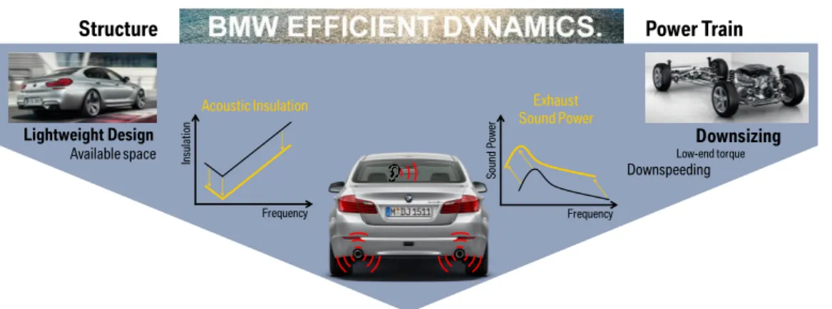
The current trend of lightweight construction combined with engine downsizing adds more difficulties in the development process. Indeed, the reduction of the number of
cylinders intensifies the excitation and the lightweight structure has an increased tendency to vibrate. A schematic representation of this context is depicted in Figure 1.2. On the one hand, the trend of downsizing, low end torque and downspeeding tends to increase the source strength q(ω) and to shift its spectrum to a lower frequency range (right side of the figure). On the other hand, the sound insulation of the vehicle tends to decrease due to the lightweight design (left side of the figure). As a result, the worst combination of low insolation and high source strength could occur more frequently. It might result in an exhaust inferred booming noise (bottom of the figure).
Figure 1.2: Schematic representation on how the BMW EfficientDynamics strategy leads to new challenges for the acoustic performance.
In other words, without additional effort, the current trend tends to deteriorate both factors involved for the exhaust sound level in a vehicle. Indeed, the exhaust sound strength 𝑄( 𝜔) at the outlet tends to increase and the transfer function 𝐻(𝐿, 𝑆, 𝜔) tends to be physically more favorable to the sound transmission.
Consequently, the demands for a descriptive and predictive method have grown. It is not anymore a question of finding a global optimum, but a necessity to achieve the same acoustical quality for the new vehicles within the presence of new, non-acoustically driven constraints.
All of this justifies the effort which is done for the description, the prediction, and the optimization of the vibro-acoustical transfer function from the exhaust outlet to the interior of a vehicle.
1.3 Exhaust sound transmission
“The discussion of any problem in science or engineering has two aspects: the physical side, the statement of the facts of the case in everyday language and of the results in a manner that can be checked by experiment; and the mathematical side, the working out of the intermediate steps by means of the symbolized logic of calculus. These two aspect are equally important and are used side by side in every problem, one checking the other. … The stating of the problem to be solved is not always the easiest part of an investigation. One must decide which properties of the system to be studied are important and which can be neglected, what facts must be given in a quantitative manner and what others need only a qualitative statement.”
Structure Power Train
Frequency Acoustic Insulation In su la tio n Downsizing Low-end torque Downspeeding Lightweight Design Available space Frequency Exhaust Sound Power So un d Po w er
1.3. Exhaust sound transmission This quotation is to be found in the introduction of the book “Theoretical Acoustics” of P.M. Morse and K. Uno Ingard [5]. This section intends to cover solely the first aspect of the discussion.
The importance of the right hypothesis
The fundamentals of sound and vibration have promised hardship to preeminent scientists such as Lord Rayleigh, Hermann von Helmholtz, Sir Isaac Newton, Marquis Pierre-Simon de Laplace, Leonhard Euler, and others.
The “error” Newton did in the calculation of the speed of sound is an edifying anecdote. He considered the “wrong” hypothesis that the thermodynamic effect of an elementary volume of air would be in the field of acoustics well described with an isothermal compression. It has led to a wrong estimation of the celerity of sound propagation. Laplace found that the adiabatic hypothesis was more adequate with the experimentally measured celerity of sound.
1.3.1
Measure
The exhaust outlet is idealized as a monopole point source of given strength. The transfer from this monopole point source to the passengers’ ears is described as a transfer function with the unit [Pa/(m3. s−2)]. A practical, though non-rigorous, approach is to represent
this transfer function as a sound insulation curve. When the monopole source is active (Figure 1.3), the sound pressure is measured simultaneously inside and outside of the vehicle with microphones. A sound insulation curve is represented in 3rd octave as the
difference in dB between the sound pressure close to the monopole point source (reference microphone) and the sound pressure inside the vehicle (listening point).
(a) (b)
Figure 1.3: (a): Sound insulation in 3rd octave representation. A minimum is observed in low frequency
range—marked with the red rectangle. This critical insulation could result in exhaust-inferred booming; (b): Measurement setup showing the external acoustic source and the microphones’ positions inside the car.
The curve of the sound insulation of a vehicle typically shows a minimum in the low frequency range. Depending on the vehicle’s architecture, this minimum could be observed in a frequency range from 30 Hz up to 140 Hz. At this frequency, the sound isolation is critical and might result in exhaust-inferred booming noise.
To certainly outline the problem of a low sound isolation, the descriptive method of the sound transmission from the exhaust to the interior of a vehicle should work at least within a frequency range starting from 20 Hz and ending up at 250 Hz.
Another determining information, is that the relationship between the cause and the
effect—i.e. source strength and pressure at a given position—is linear. Therefore, the full
study and this dissertation in particular, is realized within the framework of linear
acoustics. 10 15 20 25 30 35 40 45 50 55 Pa [dB ] f [Hz]
1.3.2
Physical description
Observability and Predictability
The easiness of the measure of the sound transmission from the exhaust outlet to the interior of a vehicle does not imply that the result is easy to interpret nor to predict. It is quite the opposite from a physical point of view. For a given phenomenon, there is no direct link between observability and predictability.
Observations
When the exhaust outlet, or a monopole source, radiates sound in the exterior of a vehicle, it results in an acoustical pressure in the interior of the vehicle. This trivial3 observation
proves that the sound can be transmitted from the exterior to the interior of a vehicle. In short, four facts are observed and depicted in Figure 1.4:
External radiation of sound. The source, exhaust outlet or loudspeaker, radiates
sound Figure 1.4 (a).
Scattering of sound. A sound field is present at the exterior of the vehicle Figure
1.4 (b).
Vibrations. The structure of the vehicle is vibrating Figure 1.4 (c).
Internal radiation of sound. There is a sound field in the interior of the vehicle
Figure 1.4 (d).
(a) (b) (c) (d)
Figure 1.4: State of the facts observed while an acoustical source like an exhaust outlet is placed in the exterior of a vehicle. From the left to the right: Radiation of sound (illustrated here by an acoustical simulation). The sound waves are reflected on the ground and on the complex external vehicle geometry. It results in a complex scattering effects; An acoustical load is present on the vehicle outer skin (illustrated here by an acoustical simulation); The car body vibrates (illustrated here by measurement of vibration of a vehicle under an acoustical excitation); A sound field is present in the interior of the vehicle (illustrated here by a simulation).
Weak coupling vision
Before going any further, the graphic and typographical conventions for the representation of the coupling of two domains are presented in Table 1.1:
Noise propagation Pressure Vibration
Semi-free field Outer skin Car body Cabin interior
1.3. Exhaust sound transmission
Table 1.1: Typographical and graphical convention for the representation of different kinds of coupling. 𝐷1
and 𝐷2 represents any arbitrary domain. In this dissertation, the frequent occurrences are 𝑓𝑙𝑢𝑖𝑑|𝑓𝑙𝑢𝑖𝑑 and
𝑓𝑙𝑢𝑖𝑑|𝑠𝑡𝑟𝑢𝑐𝑡𝑢𝑟𝑒.
Phenomenon Typography Graphical
Unspecified coupling 𝐷1|𝐷2 —
Weak coupling 𝐷1→ 𝐷2 Arrow mapping 𝐷1 to 𝐷2
Strong coupling 𝐷1↔ 𝐷2 Arrow mapping 𝐷1 to 𝐷2 and vice versa The discussion starts from the radiated sound from the source as depicted in Figure 1.5.
Figure 1.5: Physical description of the sound propagation from the exhaust outlet to the interior of a vehicle within the hypothesis of weak coupling. (𝑎): Sound waves are generated by the source results in a complex
sound pressure repartition on the outer skin of the vehicle; (𝑏): Under this dynamic acoustical load on the
outer skin, the light vehicle structure vibrates; (𝑐): The inner skin radiates sound in the interior of the vehicle; (𝑑) if the vehicle presents an aperture—e.g. open window, a leakage, or even an opened cabriolet—some
energy can be transferred from the exterior to the interior directly—i.e. without the intermediary of structural vibration.
As many physical phenomena are involved for the sound transmission from the exhaust to the interior of a vehicle, its description is not easy. Even though this description sounds complex, this vision relies on two fundamental simplifications:
Weak external coupling. The sound field resulting from the vibration of the
structure—i.e. structure acting as a secondary source—is neglected compared to the sound field created by the primary source. In other words, the external coupling 𝑎𝑖𝑟|𝑠𝑡𝑟𝑢𝑐𝑡𝑢𝑟𝑒 is considered solely in the direction 𝑎𝑖𝑟 → 𝑠𝑡𝑟𝑢𝑐𝑡𝑢𝑟𝑒, as depicted by the one direction arrow (𝑏) in Figure 1.5.
Weak internal coupling. The sound pressure in the interior of the vehicle does not
have any retroaction on the structure. It means that the internal coupling 𝑠𝑡𝑟𝑢𝑐𝑡𝑢𝑟𝑒|𝑎𝑖𝑟 is considered solely in the direction 𝑠𝑡𝑟𝑢𝑐𝑡𝑢𝑟𝑒 → 𝑎𝑖𝑟, as depicted by the one direction arrow (𝑐) in Figure 1.5.
From a formal sense, none of these two hypotheses is strictly valid, but they are often conducing to satisfying results. Actually, the second hypothesis is the basis of the field of acoustics radiation of sound. Many industrial structures are relatively stiff—i.e. high local impedance in comparison to the impedance of the air—such as, the resulting acoustical load does not impact the vibration state of the structure at all. In other words, the hypothesis is that a structural vibration results in a sound field in the air (𝑐), but that a sound field in the volume results in a neglected structural vibration.
Noise propagation Pressure Vibration
Semi-free field Outer skin Car body Cabin interior
Noise
𝑎 𝑏 𝑐
Strong coupling vision
The weak coupling approach is frequently used in acoustic radiation and is a commonly accepted hypothesis. Nevertheless, in the case of exhaust-inferred booming noise, the industrial experience shows that this bidirectional coupling cannot be neglected. This observation pointed out two additional couplings that represent the retroaction of the fluid and structure:
Internal coupling. The arrow (𝑐) describing the direct coupling 𝑠𝑡𝑟𝑢𝑐𝑡𝑢𝑟𝑒 → 𝑓𝑙𝑢𝑖𝑑 might be crossed in the reverse direction 𝑠𝑡𝑟𝑢𝑐𝑡𝑢𝑟𝑒 ← 𝑓𝑙𝑢𝑖𝑑. This reverse coupling is depicted with arrow (𝑐′).
External coupling. The arrow (𝑏) describing the coupling 𝑓𝑙𝑢𝑖𝑑 → 𝑠𝑡𝑟𝑢𝑐𝑡𝑢𝑟𝑒 might be travelled in the reverse direction 𝑓𝑙𝑢𝑖𝑑 ← 𝑠𝑡𝑟𝑢𝑐𝑡𝑢𝑟𝑒 depicted by arrow (𝑏′).
Even though, the strong coupling vision complicates drastically the physical and mathematical representation, the graphical representation is solely enriched by two arrows (𝑏′) and (𝑐′). The strongly coupled vision is depicted in Figure 1.6.
Figure 1.6: Physical description of the sound propagation from the exhaust outlet to the interior of a vehicle within the hypothesis of full coupling. (𝑎): Sound waves are generated by the source it results in a complex
sound pressure repartition on the outer skin of the vehicle; (𝑏): Under this dynamic acoustical load on the
outer skin, the light vehicle structure vibrates. (𝑐): The inner skin radiates sound in the interior of the vehicle; (𝑐′): The sound field in the interior of the vehicle retroact on the state of vibration of the structure; (𝑏′): The
vibrating structure radiates sound in the exterior. The external sound field becomes the superposition of the direct effect of the sound scattering on a rigid structure and the sound radiated by the structure.
As illustrated in Figure 1.6, the coupling between the structure and the fluid should be considered as a mutual coupling. The full coupling of the internal fluid and the structure means that the vibration has an influence on the acoustic pressure, and that this acoustic pressure retroacts on the structural vibration. The method to be developed must be able to handle this large complication.
The necessity to use experimental data
The complexity of a fully trimmed vehicle—i.e. a complete vehicle without any simplification—is still too complex to be tackled by a numerical model. Such a model should be representative of every single complexity—e.g. geometrical, physical, or coupling properties. In addition, even if a model existed for each subsystem or coupling, the question of assumptions and estimation of parameters would still remain an inextricable issue. The numerical simulation of the full trimmed vehicle is not currently possible, but NVH engineers face some immediate undesirable phenomena that can degrade the quality perceived by the customers. The booming noise is, among others, such an acoustical
Noise propagation Pressure Vibration
Semi-free field Outer skin Car body Cabin interior Noise
𝑎 𝑏 𝑐
𝑐 𝑏
1.3. Exhaust sound transmission problem which is extremely complicated to simulate. However, this kind of problem has to be understood and solutions have to be found—the solution can be a minor design change.
Anecdote of the warning triangle:
The example of a problematic booming noise on one of the BMW vehicles, is perfectly illustrative. Some engineers have found on the test rig that removing the lightweight warning triangle fixed in the trunk would have solved the problem. Removing the warning triangle was not an option; nevertheless, the problem was solved by removing a
superfluous screw. Any automotive constructor has hundreds of such anecdotes.
Despite the fact that more and more attention is carried out for the numerical simulation, the simulation might still not be able to catch this kind of detail. This observation is the consequence of deliberate strategical choices. From a practical point of view, it would be possible to design a vehicle, within the constraints, to be able to simulate everything within an acceptable precision. This strategy is followed in critical fields, such as space science or nuclear science, where tests in real conditions are extremely limited. Nevertheless, this strategy leads to dismiss some technically interesting solutions in favor of other perspectives—e.g. mass production, cost, design, performance, tight development cycle, as well as others. For all these reasons, the development in the automotive industry still relies on tests.
1.3.3
Industrial functional specifications
Up to this section, the industrial context has been presented and a qualitative physical description of the sound transmission from the exhaust outlet to the interior of a vehicle has been addressed. This section presents the resulting industrial functional specifications. The principal function of the method to be developed is:
Description and quantification of the sound transmission from the exhaust outlet into the interior of a vehicle.
The following constraint functions have to be considered:
Low frequency range. Starting from the threshold of hearing 20 Hz and up to 250
Hz.
Strong coupling. The lightweight vehicle structure is fully coupled with the air. Opened system. The vehicle might present leakage or openings.
Experimental data. Some information might be acquired with experimental
method only on available prototypes.
The experiment allows to consider the following hypothesis:
Linear acoustics. The linearity of the phenomenon has been validated.
The next section presents the current state of the art method that might be able to satisfy these industrial functional specifications.
Low frequency range
The term “low frequency” does not match a predetermined absolute frequency range and it might be confusing. The physical phenomena that occur for objects of different sizes are similar, but with a frequency shift. In this extend, there is a link between the object’s size and the “low frequency” range. For a large object the words “low frequency” match to some
Hz (typically 10-50Hz); while for a small object the words “low frequency” match to a much higher frequency (typically thousands of Hz).
From the perspective of a structural borne noise, the low frequencies are corresponding to the range in which the modal density is low. In this case, the structural waves are strongly reflected on the boundary of the system and there is almost no propagation phenomenon. All vibrations are really global—e.g. opposite to locally reacting material. It means that a single force can excite the whole structure.
1.4 State of the Art
The state of the art presented in this section addresses two goals with the following perspectives:
Industrial. Which scientific methods—framework of methods—might address or at
least partially address the industrial specifications listed in Sec. 1.4.1.
Academical. Identification of the current state of the art of the method being
selected in order to justify that the work exposed in this dissertation extends the current state of the art—Sec. 1.5.
Considering the severe industrial functional specification of the method to be developed, the framework of substructuring method is deemed to be appropriate. Indeed, these methods allow to create a model of a complex system—Sec. 1.4.1—based on the model of each of its subsystems—Sec. 1.4.2.
1.4.1
Substructuring of a complex system
“Music, poetry, and programming, all three as symbolic constructs of the human brain, are found to be naturally structured into hierarchies that have many different nested levels. Sound (phonemes) form small meaningful units (morphemes) which in turn form words; words group into phrases, which group into sentences; sentences make paragraphs, and these are organized into higher levels of meanings. Notes form musical phrases, which form themes, counterpoints, harmonies, etc.; which form movements, which form concertos, symphonies, and so on. The structure in programs is equally hierarchical, if not so universally recognized.” [6].
The word “substructuring” refers in the field of mechanics to a piecewise description of a “structure”. If the model being created intends to represent dynamic properties of this structure, it is part of the framework of “dynamic substructuring”. According to M. V. van der Seijs, a substructuring approach assumes that the dynamic interaction between the subsystems takes place at a limited set of interfaces [7].
D. de Klerk has listed [8] four advantages of a component wise vision over a global method where the full system is handled at once:
Handling of large structure. Handling a large and complex system as a whole
might be problematic—e.g. size of the numerical model and the experimental facilities.
Effect of a subsystem. Identification and optimization of a local problem.
Elimination of non-relevant subsystems on the assembled system.
Hybrid model. Subsystem might be modeled separately by the best appropriated
1.4. State of the Art
Organization. Sharing and combining substructures from different actors.
In the following, three classes of methods are addressed.
Impedance and Mobility
The concept of electrical impedance has been introduced in 1884 by Heaviside [9]. In the late 19th, the research in the field of electrical network has been increased by the needs of
the commercial development of the telegraph and the telephone. The concept of electrical impedance combined with other practical tools—e.g. theorems of Kirchhoff, Thévenin, Norton—has allowed a systematic depiction of complex electrical networks. Progressively it has been possible to describe an electrical network as several “subsystems” interacting together with physical quantities current and voltage—i.e. “through” and “across”. According to the review paper of Gardonio [10], Webster has been the first to propose the use of the concept of electrical impedance for the needs of mechanics [11]. Nevertheless, the analogy between electrical and mechanical systems has not been straightforward. On the opposite, many years of controversy have been necessary. The first analogy proposed by Webster—subsequently called direct analogy—is based on the following consideration:
Force [N]. “cause” of the motion, equivalent to the electromotive force “across” [V].
Velocity [m. s−1]. “effect” of the force, equivalent to the current “through” [A].
Impedance [N/(m. s−1)]. Defined as the ratio Force/Velocity.
Unfortunately, the direct analogy proposed by Webster has suffered many limitations and even some incoherencies. Firestone has proposed in 1933 “A new analogy between mechanical and electronical systems” [12]. The so-called inverse analogy is founded on:
Force [N]. Equivalent to the current “through” [A].
Velocity [m. s−1]. “effect” of the force, equivalent to the current “across” [V].
Bar Impedance4 subsequently called Mobility [m. s−1/N]. Defined as the ratio
Velocity/Force.
Le Corbeiller had sided in “Duality in Mechanics” with the mobility analogy vision proposed by Firestone [13]. Despite a somewhat less intuitive depiction of a mechanical system (electrical node does not match a mechanical node; electrical mesh does not match a mechanical loop) the vision of Firestone is conform to the principle of duality5. This
conformity allows overcoming all difficulties encountered with the impedance vision. The inverse analogy proposed by Firestone is still in use today. In its paper “Twixt Earth and Sky with Rod and Tube; the Mobility and Classical Impedance Analogies” [12], Firestone proposes a set of tools allowing the depiction of a complex mechanical network with both, the classical analogy—i.e. direct analogy—and the inverse analogy—i.e. mobility.
4 Firestone if arrived first would have called impedance the ratio Velocity/Force and not the ratio
Force/Velocity as done by Webster. In [12] he has proposed to use the word bar impedance instead. The intention was that the prefix bar would dismiss with time after the adoption of his vision. And so, the world impedance would have been redefined has Velocity/Force. Even if Firestone vision’s has been more and more adopted, the definition of mechanical impedance proposed by Webster [11] has not been changed. Actually, the word mobility has been adopted instead. As a result, a
mechanical mobility is in some measure the pendant of an electrical impedance.
5 The duality in mechanics is an important concept with major consequences. One of which is the
principle of reciprocity. The application of the principle of reciprocity in vibro-acoustics is exposed by Fahy in [96].
As the adoption of the mobility instead of impedance has been a long controversy, O'Hara has summarized the major differences in [14]. He wrote in the conclusion: “Mobilities
describe invariant characteristics of the whole structure, impedance generally concern themselves only with segments. Impedance are dependent upon the number of observation points considered and, consequently, do not possess invariant characteristics”.
Principle of sufficient reason: “Cause”, “Effect”, philosophy 6 and
metaphysics.
The difficulty of the adoption of the mobility—indirect analogy—vision in comparison to the impedance—direct analogy is probably rather a philosophical consideration. In the 17th
the “principle of sufficient reason” developed by Leibniz had created a deep metaphysical sense of “cause” and “effect”. Le Corbeiller wrote a philosophical aside [13]: “The reader
may wonder how it is possible to derive the dynamical behavior of a system from kinematic equations. This question arises because we are accustomed in dynamics to a mistaken emphasis on forces, traceable to a metaphysical attitude current in Newton’s times. From this emphasis on force considered as the “cause” of motion, there followed in electricity an emphasis on electromotive force considered as the “cause” of the current flow. To one without such preconceptions, it should be clear that in Ohm’s law E = IR, as
well as in Newton’s law f = ma, the general gas law PV = nRT, or any natural law
whatsoever, there is no cause and no effect, there are only variable physical quantities permanently connected by a mathematical equation. For instance, whenever any two of the quantities E, I, R are known at any time t Ohm’s law allows us to find the third one; if I and R happen to be known, it would make little sense to call them the “cause” of E, and
call E their “effect” ”.
The need of considering systems with multiple inputs and multiple outputs has been addressed by Rubin in “Transmission matrices for vibration and their relation to admittance and impedance” [15]. Each subsystem is characterized with impedance or mobility matrices. In a further development he addressed in “Mechanical Immittance- and Transmission-Matrix Concepts” [16] the operations necessary to assemble subsystems together.
The impedance/mobility framework is still an open area of research. Nowadays, the efforts are mainly concentrated on two aspects: the characterization of a subsystem by means of inverse method such as exposed by Höller in [17] on the one hand, the consideration of complex interfaces—i.e. line or surface instead of points—on the other hand. As an example of the research of Meyer exposed in “prediction of the vibroacoustic behavior of a submerged shell with non-axisymmetric internal substructures by a condensed transfer function method” proposes a method to address line interfaces [18].
Kim suggest “a compact matrix formulation using the impedance and mobility approach for the analysis of structural-acoustics systems” [19]. This work has extended the application of the mobility method to vibro-acoustical system—i.e. system with a structure and a fluid. The Patch Transfer Functions method has also been developed with the intention to address the field of vibro-acoustics.
6 From the side of history, philosophy and sociology of the scientific knowledge, the philosopher T.
1.4. State of the Art
Patch Transfer Functions method (PTF)
Entering the 21st century, the mobility method has been adapted for the needs of acoustics
and vibro-acoustics. The main challenge was the consideration of continuous interfaces— as often encountered in acoustics and vibro-acoustics. Both visions, impedance and
mobility, have been addressed.
Cacciolati initiated first a mobility approach for acoustic problem: “acoustic mobility for vibroacoustic prediction” [20]. The continuous coupling interface is discretized in elementary surfaces called patches. The term “patch-mobility method” was born. The method relies on the characterization of each uncoupled subsystem—by means of either numerical, analytical or measurement method. Once a database of mobilities—stored in matrices—is complete, the framework of the mobility method allows to calculate the response of the coupled system.
After the resolution of some numerical complications, such as the inversion of
ill-conditioned matrices, many applications have been proposed. Chazot has addressed the
problem of “prediction of transmission loss of double panels with a patch-mobility method” [21]. After some additions, this work has been published under the title: “transmission loss of double panels filled with porogranular materials” [22]. A year later, Guyader added the consideration of stiffeners: “transmission loss prediction of double panels filled with porous materials and mechanical stiffeners” [23].
In opposition to Cacciolati who sided in 2000 with the mobility approach [20], Maxit sided with the impedance approach. As a result, he presented in 2002 a similar approach for acoustical system: “airborne noise prediction using patch acoustic impedance” [24]. The term “patch-impedance” was born. The name of the method has been subsequently changed to “Patch Transfer Functions” (PTF). The paper of Ouisse: “Patch Transfer Functions as a Tool to Couple Linear Acoustic Problems” is a milestone in the development of this method [25]. Indeed this papers addresses, the theoretical framework of the method, a numerical validation—covering the convergence of the method and other numerical considerations—and concludes with a successful application on an automotive. By using the vibro-acoustics substructuring method Patch Transfer Functions, a coupled system can be considered as several subsystems connected through elementary surfaces called patches. In terms of methodology, the large and complex problem can be broken down into simpler sub-problems. Various methods can then be applied on these patches to calculate the vibro-acoustical behavior of each subsystem. Upon the attainment of these individual vibro-acoustical responses, the acoustical response of the fully coupled system can be predicted by reassembling the subsystems using continuity relations. One example of a hybrid PTF model is found in “a Combined Computational-Experimental Approach for Modelling of Coupled Vibro-Acoustic Problems” experimented by Rejlek [26].
If the controversy of the 20th century “impedance” versus “mobility” had slowly turned in
the advantage of the “mobility”, the opposite has happened in the field of acoustics. Starting at the beginning of the 21st century both alternatives “patch-mobility method”
versus “patch-impedance method” has been developed simultaneously. Nevertheless, in this case the approach in terms of “impedance” has been found numerically more stable than the “mobility” one. As a result the Patch Transfer Function (PTF) has been further developed.
As the method has gained more and more interest in the last two decades, several studies have been published. Motivated by industrial needs—automotive pass-by noise—Totaro has proposed an “Extension of the Patch Transfer Functions method (PTF method) to high
frequency domain (sub-cavities decomposition)” [27]. In this study, the division of a large size cavity, into smaller sub-cavities, allows to reduce the total number of modes that must be computed Figure 1.7.
Figure 1.7: Patch Transfer Functions method model of an engine compartment. Coupling velocities at 200 Hz. Left: 1 cavity; Right: 2 sub-cavities. The model with 2 sub-cavities allows to decrease the computational cost (less modes)—or to extend the upper frequency for the same computational cost. This figure is found in [27].
After many applications for airborne noise configuration, the Patch Transfer Functions method has been applied to underwater structures such as encountered for submarines [28]. Considering the FEM computation of Patch Transfer Functions for the coupling in heavy fluid, Aucejo encountered convergence issues. As a result, he proposed the article “convergence acceleration using the residual shape technique when solving structure– acoustic coupling with the Patch Transfer Functions method” [29]. Maxit has continued to improve this technique resulting in: “improving the Patch Transfer Function Approach for Fluid-Structure Modelling in Heavy Fluid” [30].
As acoustical material are of great use for acoustics, some studies have covered this aspect. Maxit has investigated the “modeling of micro-perforated panels in a complex vibro-acoustic environment using patch transfer function approach” [31]. Veronesi has proposed “Patch Transfer Function Approach for Analysis of Coupled Vibro-Acoustic Problems Involving Porous Materials” [32]. Based on an extension of this work, Albert has proposed the “Prediction of the vibro-acoustic response of a structure-liner-fluid system based on a patch transfer function approach and direct experimental subsystem characterisation” [33].
The creation of a Patch Transfer Functions model allows a correct physical description of a problem of acoustics or vibro-acoustics. As the model is extremely small—i.e. matrices involved in the PTF calculation are much smaller than the one involved in a FEM or BEM calculation—it allows running optimization algorithms. In “efficient positioning of absorbing material in complex systems by using the Patch Transfer Function method”, Totaro has illustrated one application of acoustical optimization [34].
Statistical energy analysis (SEA)
The Statistical Energy Analysis (SEA) has been developed in the sixties. Based on the generalization of power balance between coupled oscillators, this method estimates the energy exchanges between weakly coupled subsystems. The extreme simplicity of the system of equations to be solved is due to the use of random variables and random excitations and relies on several constraining assumptions that are mostly valid at high frequency. Conversely, in this frequency range, the Finite Element methods are facing
1.4. State of the Art some difficulties related to the size of the model (the number of degrees of freedom increases with frequency) and to high variabilities of the structures in high frequency. Le Bot [35] considers SEA as the pendant of thermodynamics in the field of sound and vibration. The fundamental of SEA is the “coupling power proportionality”. It states that two subsystems are exchanging a power proportionally to the difference of “vibrational
temperature”. The factor of proportionality is called “coupling loss factor”. Working with
scalars instead of displacements and velocities has several advantages. Nevertheless, this approximation relies on several hypotheses partially reviewed by T. Lafont [36]: Random forces such as rain-on-the-roof; diffuse field; energy equipartition; conservative, weak and direct coupling; light damping.
As the SEA method is based on power transfer between subsystems, it is part of the framework of substructuring. The drawback is that the substructure must be defined respecting the hypotheses of SEA. In this case, the weak coupling hypothesis is the most important one and often the most difficult to guarantee. J.-L. Guyader [37] and N. Totaro [38] tackle this problem by introducing an automatic partitioning technique analyzing energy transfer function with a clustering algorithm. An index—MIR for Mutual Inertia Ratio—allows to check the validity of the proposed structural partitioning. A low value indicates a weak coupling and supports the usage of the SEA method.
The substructuring with SEA has been applied to many industrial structures. N. Totaro has applied it to the case of a high-speed train TGV-Duplex [39]. M. Kassem has proposed an application in the field of automotive “Structural partitioning of complex structures in the medium-frequency range. An application to an automotive vehicle” [40]. For structure of growing complexity, a judicious partitioning might be time consuming. In this context, C. Díaz-Cereceda has proposed an “Automatic subsystem identification in statistical energy analysis” [41]. Some other applications are found in the field of complex acoustical network such as proposed by A. Bocquillet in [42].
SEA hypotheses are generally met in the high frequency range. The frequency gap between low frequency addressed by FE methods and the high frequency solved by SEA is still an open topic in the field of sound and vibration.
Statistical modal Energy distribution Analysis (SmEdA)
The Statistical modal Energy distribution Analysis (SmEdA) first proposed by L. Maxit is an extension of SEA with the relaxation of the hypothesis of equipartition of modal energies [43]. The relaxation of this hypothesis allows to tackle the problem of strong coupling, low modal density and localized force. As a result, this method is well suited for the mid frequency range.
The method relies on the calculation of the coupling loss factors between the modes of the uncoupled subsystems by means of Finite Element Method calculations applied on uncoupled subsystems. The theory is presented in “Estimation of SEA coupling loss factors using a dual formulation and FEM modal information, Part I: Theory” [44]. This paper is completed with a numerical validation [45]. Further developments are presented in “Extension of SEA model to subsystems with non-uniform modal energy distribution” [46]. The method is validated on a laboratory setup and on some parts of vehicles (truck cabin, car firewall, side glazing of a car excited by a Turbulent Boundary Layer, etc…). N. Totaro [47] has demonstrated in “SEA Coupling Loss Factors of Complex Vibro-Acoustic Systems” that SmEdA can be applied on a structure-to-cavity coupling and has shown an application on a complex automotive system.
Finally, H. D. Hwang has introduced the possibility of local distribution of dissipative treatment in “SmEdA vibro-acoustic modelling in the mid-frequency range including the effect of dissipative treatments” [48] [49].
1.4.2
Characterization of a subsystem
Characterization by means of numerical modelling
The physical domain is generally described with local fundamental principles of mechanics: law of conservation of mass and Newton’s second law 𝐹⃗ = 𝑚𝑎⃗. These local principles are often represented with differential equations such as the equation of Navier-Stokes [50]. For an acoustical medium it results to the Helmholtz’s equation [51]. In order to fully describe the system some information about the boundary such as imposed stresses or displacement are necessary [52].
Solving this set of differential equations—i.e. local and boundary conditions—might be done analytically for simple academical cases. For more complex systems, many numerical methods are able to find an approached solution. The Finite Element Method (FEM) and the Boundary Element Method (BEM) are among the most common in the field of vibro-acoustics [53].
FEM
“The limitations of the human mind are such that it cannot grasp the behaviour of its complex surroundings and creations in one operation. Thus the process of subdividing all systems into their individual components or ‘elements’, whose behaviour is readily understood, and then rebuilding the original system from such components to study its behaviour is a natural way in which the engineer, the scientist, or even the economist proceeds.” [54].
The Finite Element Method (FEM) is a versatile numerical method to solve problems described by means of partial differential equations. The partial differential equations are representing a local problem of equilibrium, written with a variational formulation [55]. The latter are written in terms of interpolation functions, describing a relation between the nodes of an element. An element is defined by a set of nodes and an interpolation function. The mesh is a set of elements.
Finally, the set of partial differential equations to be solved turns into the resolution of a linear set of equations. The latter is written with matrices as proposed in Eq. 1.3 for the case of NVH:
[𝐾 + 𝑖𝜔𝐷 − 𝜔2𝑀]{𝑋} = {𝐹} (1.3)
The stiffness matrix 𝐾, the damping matrix 𝐷 and the mass matrix 𝑀 are representing inherent properties of the system. The vectors {𝑋} and {𝐹} are describing the response of the system. Vector {𝑋} represents the response at each node in terms—displacement or pressure. Vector {𝐹} represent the effort applied to the nodes.
Eq. 1.3 might be solved directly or using a modal basis. If all modes are considered this approach does not result in an additional approximation. Nevertheless, considering all modes would not bring any computational cost reduction. The interest of the modal synthesis is that the solution up to a given frequency is well approximated with a reduced number of modes.