HAL Id: tel-00698421
https://tel.archives-ouvertes.fr/tel-00698421
Submitted on 16 May 2012
HAL is a multi-disciplinary open access
archive for the deposit and dissemination of sci-entific research documents, whether they are pub-lished or not. The documents may come from teaching and research institutions in France or
L’archive ouverte pluridisciplinaire HAL, est destinée au dépôt et à la diffusion de documents scientifiques de niveau recherche, publiés ou non, émanant des établissements d’enseignement et de recherche français ou étrangers, des laboratoires
fluctuations
Hongying Zhu
To cite this version:
Hongying Zhu. Thermal energy harvesting from temperature fluctuations. Other [cond-mat.other]. INSA de Lyon, 2011. English. �NNT : 2011ISAL0086�. �tel-00698421�
N° d’ordre 2011-ISAL-0086
Année 2011
THÈSE
Récupération d’Énergie Thermique à
partir de Variations de Température
-
Thermal Energy Harvesting from
Temperature Fluctuations
présentée devant
L’Institut National des Sciences Appliquées de Lyon
Pour obtenir
Le grade de DOCTEUR
École doctorale : Électronique, Électrotechnique et Automatique de Lyon
Spécialité : Énergie et Systèmes
Par
Hongying ZHU
INSA de Lyon, FRANCE
Soutenue le 29 Septembre 2011 devant la Commission d’examen
Rapporteur
Pr. Amen AGBOSSOU
Examinateur
Pr. François BAUER
Rapporteur
Dr. Yves BERNARD
Directeur
Pr. Daniel GUYOMAR
Co-directeur
Dr. Sébastien PRUVOST
Laboratoire de recherche : Laboratoire de Génie Électrique et Ferroélectricité
(LGEF) de l’INSA de Lyon
INSA Direction de la Recherche - Ecoles Doctorales – Quinquennal 2011-2015
SIGLE ECOLE DOCTORALE NOM ET COORDONNEES DU RESPONSABLE
CHIMIE CHIMIE DE LYON http://www.edchimie-lyon.fr
Insa : R. GOURDON
M. Jean Marc LANCELIN
Université de Lyon – Collège Doctoral Bât ESCPE
43 bd du 11 novembre 1918 69622 VILLEURBANNE Cedex Tél : 04.72.43 13 95
[email protected] E.E.A. ELECTRONIQUE, ELECTROTECHNIQUE, AUTOMATIQUE
http://edeea.ec-lyon.fr
Secrétariat : M.C. HAVGOUDOUKIAN [email protected]
M. Gérard SCORLETTI
Ecole Centrale de Lyon 36 avenue Guy de Collongue 69134 ECULLY
Tél : 04.72.18 60 97 Fax : 04 78 43 37 17
[email protected] E2M2 EVOLUTION, ECOSYSTEME, MICROBIOLOGIE, MODELISATION
http://e2m2.universite-lyon.fr
Insa : H. CHARLES
Mme Gudrun BORNETTE
CNRS UMR 5023 LEHNA
Université Claude Bernard Lyon 1 Bât Forel
43 bd du 11 novembre 1918 69622 VILLEURBANNE Cédex Tél : 04.72.43.12.94
[email protected] EDISS INTERDISCIPLINAIRE SCIENCES-SANTE
http://ww2.ibcp.fr/ediss
Sec : Safia AIT CHALAL Insa : M. LAGARDE
M. Didier REVEL
Hôpital Louis Pradel Bâtiment Central 28 Avenue Doyen Lépine 69677 BRON
Tél : 04.72.68 49 09 Fax :04 72 35 49 16
[email protected] INFOMATHS INFORMATIQUE ET MATHEMATIQUES
http://infomaths.univ-lyon1.fr
M. Johannes KELLENDONK
Université Claude Bernard Lyon 1 LIRIS - INFOMATHS Bâtiment Nautibus 43 bd du 11 novembre 1918 69622 VILLEURBANNE Cedex Tél : 04.72. 43.19.05 Fax 04 72 43 13 10 [email protected] Matériaux
MATERIAUX DE LYON M. Jean-Yves BUFFIERESecrétaire : Mériem LABOUNE INSA de Lyon
École Doctorale Matériaux Mériem LABOUNE
Bâtiment Antoine de Saint-Exupéry 25bis Avenue Jean Capelle
69621 VILLEURBANNE Tel : 04 72 43 71 70 Fax : 04 72 43 72 37
MEGA MECANIQUE, ENERGETIQUE, GENIE CIVIL, ACOUSTIQUE (ED n°162) M. Philippe BOISSESecrétaire : Mériem LABOUNE
Adresse : INSA de Lyon
École Doctorale MEGA Mériem LABOUNE
Bâtiment Antoine de Saint-Exupéry 25bis Avenue Jean Capelle
69621 VILLEURBANNE Tel : 04 72 43 71 70 Fax : 04 72 43 72 37
Site web : http://www.ed-mega.com
ScSo ScSo*
M. OBADIA Lionel
Sec : Viviane POLSINELLI Insa : J.Y. TOUSSAINT
M. OBADIA Lionel Université Lyon 2 86 rue Pasteur 69365 LYON Cedex 07 Tél : 04.78.69.72.76 Fax : 04.37.28.04.48 [email protected]
If we knew what we were doing
,
it
wouldn't be called research
,
would it
?
Abstract
The development of portable equipments, wireless sensors networks and self-powered devices in a general manner generates a strong demand for micro-energy harvesting devices. One of the most challenging ways to self power devices is the development of systems that recycle ambient energy and continually replenish the energy consumed by the system. Apart from electromechanical energy harvesting, it is also interesting to convert thermal energy, which is “available” everywhere, into suitable electrical energy.
In this thesis, the thermal to electrical energy conversion from temperature fluctuations was developed and improved, and the feasibility of this technique was also confirmed by implementing the experimental experiment. Among different ferroelectric materials, PZN-4.5PT single crystal and P(VDF-TrFE-CFE) 61.3/29.7/9 mol% were chosen as active materials due to their outstanding properties under electric field. By means of some intelligent thermodynamic cycles, e.g., Ericsson or Stirling cycle, which has been presented in previous research, the efficiency of energy conversion could be improved greatly.
In the first part, pyroelectric energy harvesting on PZN-4.5PT single crystals with an Ericsson cycle was mainly investigated from two aspects: frequency effect and phase transitions. It was shown that the harvested energy demonstrated a nonlinear decrease with an increase of frequency, and the optimal use of the phase transitions during the Ericsson cycle could greatly improve the harvested energy by choosing the appropriate working temperature range. Based on it, two asymmetric Ericsson models (L-H and H-L cycles) were attempted successfully, and it was confirmed that the H-L cycle is the most effective thermal energy harvesting cycle for this material.
The second part concentrated on electrostatic energy harvesting by nonlinear capacitance variation on P(VDF-TrFE-CFE) 61.3/29.7/9 mol% terpolymer. Ericsson cycle was tested experimentally between 25 and 0°C and compared with the simulation from dielectric constant values obtained under DC electric field. The identical result between simulation and
experiment proved the reliability of our theoretical evaluation. It was found, from simulation, that the harvested energy increased up to 240 mJ/cm3 when raising the electric field at 80 kV/mm. The further study on Ericsson and Stirling cycle was also made under different temperature and electric field conditions for evaluation. The harvested energy increases with the rising of temperature variation and electric field in both cycles, but in contrast to Ericsson cycle, Stirling cycle can harvest more energy for the same injected energy.
Résumé
Le développement des équipements portables, des réseaux de capteurs sans fil et systèmes auto-alimentés d'une manière générale génère une forte demande pour les dispositifs de récupération de micro-énergie. Une des voies les plus intéressantes pour auto-alimenter des dispositifs consiste à développer des systèmes recyclant l'énergie ambiante afin de renouveler sans cesse l'énergie consommée par le dispositif. En dehors de la récupération d'énergie électromécanique, il est également intéressant de convertir l'énergie thermique, qui est «disponible» partout, en énergie électrique.
Au cours de cette thèse, la conversion d’énergie thermique en énergie électrique fondée sur des variations temporelles de température a été développée et améliorée. Parmi les matériaux ferroélectriques, des monocristaux de PZN-4.5PT et le terpolymère P(VDF-TrFE-CFE) 61.3/29.7/9 mol % ont été choisis comme matériaux actifs en raison de leurs propriétés remarquables sous champ électrique. En utilisant des cycles thermodynamiques intelligents, par exemple, Ericsson ou à cycle de Stirling, l'efficacité de la conversion de l'énergie pourrait être considérablement améliorée.
Dans la première partie, la récupération d'énergie pyroélectrique en utilisant des monocristaux de PZN-4.5PT a été principalement étudiée sous deux aspects: l'effet de fréquence et des transitions de phase sur les cycles d’Ericsson. Il a été montré que l'énergie récupérée diminue de façon non linéaire avec une augmentation de la fréquence. De plus, l’utilisation optimale des transitions de phase pendant le cycle d’Ericsson permet d’améliorer grandement l’énergie récupérée en choisissant une gamme de température de travail appropriée. A partir de ces résultats, deux cycles d’Ericsson asymétriques (LH et HL) ont été réalisés avec succès. Avec les monocristaux de PZN-4.5PT, le cycle HL est le cycle le plus efficace pour la conversion d’énergie thermique en énergie électrique.
La deuxième partie traite de la récupération d'énergie électrostatique via la variation non linéaire de la capacité du terpolymère P(VDF-TrFE-CFE) 61.3/29.7/9 mol %. Un cycle
d’Ericsson a été réalisé entre 25 et 0°C et comparé à sa simulation à partir de la valeur de la constante diélectrique sous champ électrique DC. La concordance entre la simulation et l’expérience a prouvé la fiabilité de notre évaluation théorique. A partir de la simulation, l'énergie récupérée augmente jusqu'à 240 mJ/cm3 en appliquant un champ électrique de 80 kV/mm. Des cycles de Stirling et d’Ericsson ont également été simulés sous différentes variations de température et champ électriques. L'énergie récupérée augmente avec l’accroissment de la variation de température et de la valeur du champ électrique appliqué et ceci quelque soit le cycle réalisé. Contrairement au cycle d’Ericsson, un cycle de Stirling peut récupérer plus d'énergie pour une même énergie injectée.
Acknowledgements
First and foremost, I would like to sincerely thank Prof. Daniel Guyomar for serving as my advisor. It has truly been an honor to work with him on the cutting edge of research in the field of Energy harvesting. His strong work ethic and creative thinking is contagious to me and will influence me throughout my professional career. I would also like to thank Dr. Sébastien Pruvost for serving as my co-advisor, for his sense of responsibility, incredible patience, and numerous fruitful discussions. His enlightening guidance and encouragement is the powerful support for my work.
I would like to thank Pr. Amen AGBOSSOU, Pr. Francois BAUER, Dr. Yves BERNARD for their contributions as committee members and for their comments and suggestions that improved the quality of this work.
Next, I would like to thank Dr. Pierre-Jean Cottinet for his generous help, our pleasant cooperation made a great promotion to this thesis. I would also like to thank Dr. Gaël Sebald for his constructive advices on my work.
I would like to express my gratitude to Dr. Laurence Seveyrat for providing help and advice in synthesizing the polymers. Besides, the experimental work could not have progressed so quick without the support of Verinique Perin. Thanks also go to Mr. Frederic Defromerie for machining the art-like device for my design and experiment.
I am extremely thank Evelyne Dorieux, secretary of Laboratory, for her supporting. She is not only my colleague in lab, but also a bosom friend, I will never forget her kindly help.
I will not be able to list the names of all whom I feel grateful to, but I would like to express my gratitude to all of the members of LGEF. Without a doubt, I am proud to be one of them, their optimistic and positive spirit, their serious in work and humorus in life accompany with me during all the life in LGEF.
In addition, I would like to acknowledge the China Scholarship Council (CSC) for their financial support and the Co-operation program between CSC and UT-INSA.
Finally, I want to thank my father, ZHU Dezhou, mother, LI Shuilian, brother, ZHU Chaoqun. Their support is the source of power to pursue my life goal. I extremely want to express my deepest gratitude and love to my husband, SHI Xueyuan, without his considerable understanding, tremendous support at work and life, I could never reach this joyful moment. This thesis is dedicated to him.
Table of contents
Abstract …... ... iii
Résumé ... v
Acknowledgements ... vii
Table of contents ... 1
Nomenclature & Abbreviations ... 3
Introduction ... 5
Chapter 1 Literatures Review and General Concepts of Different Techniques of Energy Harvesting ... 7
1.1 Motivation ... 7
1.2 Energy Harvesting Principles ... 9
1.3 Summary of Potential Energy Sources and the corresponding technique .... 12
1.3.1 Solar Energy ... 12
1.3.2 Radio Frequency Energy ... 13
1.3.3 Human Power ... 14
1.3.4 Vibration Energy ... 15
1.3.5 Thermal Energy ... 24
1.4 Objective of this work ... 36
Chapter 2 Principle of Thermal Energy Harvesting and Characterization of Ferroelectric Phenomena ... 39
2.1 Pyroelectric Effect ... 39
2.2 Electrocaloric Effect ... 44
2.3 Modeling of Pyroelectric Energy Harvesting ... 44
2.4 Temperature Effect on Capacitance (Dielectric Constant) in Ferroelectric Materials ... 46
2.5 Thermodynamic Cycles of Thermal Energy Harvesting ... 47
2.5.1 Ericsson Cycle (Olsen Cycle) ... 48
2.5.2 Stirling Cycle ... 50
2.6 Ferroelectric Materials Background ... 51
2.6.1 Ferroelectric Phase and Curie Temperature ... 51
2.6.2 Polarization Reversal and Hysteresis Loop ... 52
2.6.3 Domain Engineering of PZN-PT Relaxor Ferroelectric Single Crystal ... 53
Chapter 3 Thermal Energy Harvesting from Pb(Zn1/3Nb2/3)0.955Ti0.045O3 Single Crystals Phase Transitions ... 57
3.1 Introduction ... 58
3.2 Materials Consideration ... 59
3.2.1 Brief Description of Relaxor Ferroelectric Single Crystals ... 59
3.2.3 Preparation of PZN-4.5PT ... 69
3.2.4 Characterization of PZN-4.5PT ... 70
3.3 Thermal Energy Harvesting from Pb(Zn1/3Nb2/3)0.955Ti0.045O3 Single Crystals ... 77
3.3.1 Experimental Section ... 77
3.3.2 Ericsson Pyroelectric Cycle ... 79
3.3.3 Results and Discussion ... 81
3.3.4 Asymmetric Ericsson Cycle ... 87
3.4 Conclusions ... 88
Chapter 4 Energy Harvesting by Nonlinear Capacitance Variation for Relaxor Ferroelectric P(VDF-TrFE-CFE) Terpolymer ... 91
4.1 Introduction ... 91
4.2 Material Consideration ... 92
4.2.1 PVDF and its Copolymers ... 92
4.2.2 PVDF-based Terpolymer ... 96
4.3 Energy Harvesting by Nonlinear Capacitance Variation for a Relaxor Ferroelectric P(VDF-TrFE-CFE) Terpolymer ... 103
4.3.1 Introduction ... 103
4.3.2 Preparation of Terpolymer P(VDF-TrFE-CFE) ... 105
4.3.3 Principle of Electrostatic Energy Conversion ... 105
4.3.4 Characterization of terpolymer P(VDF-TrFE-CFE) ... 108
4.3.5 Electrostatic Energy Harvesting by Nonlinear Capacitance Variation for a Relaxor Ferroelectric P(VDF-TrFE-CFE) ... 114
4.4 Simulation of Ericsson and Stirling Cycle ... 122
4.4.1 Introduction ... 122
4.4.2 Theoretical Model for Simulation ... 122
4.4.3 Result and Discussion ... 123
4.5 Conclusion ... 129
Conclusions and Future Work ... 131
Author’s Contributions ... 131
Research Conclusions ... 133
Suggestions for Future Work ... 135
List of Publications ... 137 French Part ... 139 Résumé chapitre 1 ... 141 Résumé chapitre 2 ... 143 Résumé chapitre 3 ... 145 Résumé chapitre 4 ... 147 Bibliography ... 149 List of Figures ... 159 List of Tables ... 163 FOLIO ADMINISTRATIF ... 166
Nomenclature & Abbreviations
Nomenclature
Symbol
Signification
A Surface of electrode c Calorific capacity C Curie-Weiss constantCmax Maximum capacitance
Cmin Minimum capacitance
Cr Capacitance D Electric Displacement e Strain E Electric field Ec Coercive field f Frequency
FOM Figure of merit for pyroelectric energy Harvesting p Pyroelectric coefficient
Pmax Harvested power
Ps Spontaneous Polarization
Pr Remnant polarization
Q Charge
Qhot Thermal energy taken from the hot medium
U Internal energy
V Voltage
W Energy
Wharvest Harvested energy
Winject Injected energy
Wmax Harvested energy per unit of volume
Γ Entropy
δWcycle Harvested energy in one cycle
ε0 Vacuum permittivity
η Conversion ratio
ηcarnot Conversion ratio in Carnot cycle
θ Temperature θc Curie temperature σ Stress χ Electric susceptibility 33θ ε Dielectric permittivity
Abbreviations
Symbol
Signification
ECE Electrocaloric Effect
MEMS Micro-Electro-Mechanical System MsM Magnetostrictive Materials
PZT Piezoelectric
PVDF Polyvinylidene Fluoride PZN-4.5PT Pb(Zn1/3Nb2/3)0.955Ti0.045O3
P(VDF-TrFE) Poly(vinylidene fluoride-trifluoroethylene)
P(VDF-TrFE-CFE) Poly(vinylidene fluoride-trifluoroethylene-chlorofluoroethylene)
Introduction
Over the years, there has been a growing interest in stand-alone systems in numerous application fields, such as embedded sensors in buildings, medical implants, and other remote wireless sensing nodes. In many applications, the problem posed by these devices is how to supply the required power. In addition, constant advances in electronics push past boundaries of integration and functional density toward completely autonomous microchips embedding their own energy source. In these cases, research continues to develop higher energy-density batteries, but the amount of energy available is finite and remains relatively weak, limiting the system’s lifespan, which is paramount in stand-alone systems or portable electronics and may induce a costly maintenance, in the case of contaminated areas for instance. Moreover, batteries dying without warning poses serious problems in safety monitoring applications. Extended life is also particularly advantageous in systems with limited accessibility, such as biomedical implants, structure-embedded microsensors, or safety monitoring devices in harsh environments and contaminated areas. Accordingly, supplying systems with power over the lifespan of a structure is a significant challenge. To solve all these problems, sustainable power generation may be achieved in converting ambient energy into electrical energy.
Energy harvesting aims to collect ambient energy to help power systems, possibly storing energy when it is not required. Different systems are already available: solar cells and electromechanical conversion for harvesting from vibrations or from mechanical stress (i.e. produced by a person walking or an object movement). The interest of researchers is continuously increasing in the framework of clean energy sources. One energy source -- thermal energy -- is rarely harvested although being ‘available’ everywhere. In the daily life, large amounts of waste heat are released from power, refrigeration, and heat pump cycles. In this dissertation, we concentrate on a promising approach – thermal energy harvesting from temperature variation.
The objective and motivation of this study is to develop a new energy harvester that may be particularly suited to satisfying the small scale power generation demands of applications. There are two methods we mainly investigated for thermal energy harvesting: (1) pyroelectric energy harvesting in PZN-4.5PT single crystal, and (2) electrostatic energy harvesting in P(VDF-TrFE-CFE) 61.3/29.7/9 mol% terpolymer. We hope the results obtained in this work could promote the development of thermal energy harvesting.
Chapter 1
Literatures Review and General
Concepts of Different Techniques of
Energy Harvesting
1.1 Motivation
With the recent development of wireless and integrated electronics, the demand for portable electronics and wireless sensors has demonstrated a rapid growth, as has the demand for structural sensors in buildings, medical implants, global positioning system (GPS) tracking devices on animals in the wild or safety-monitoring devices in harsh environments and contaminated areas. Due to such devices being portable, it becomes necessary for them to carry their own power supply. Indeed, in most of the above-mentioned applications, the system is completely embedded in the host structure and physical connections with the outside world are impossible.
The conventional solution is to utilize electrochemical batteries. However, this entails drawbacks, e.g., the finite lifespan of such batteries. Moreover, retrieving the system simply to replace or recharge the battery is a very costly task, and is sometimes even impossible. Another great drawback, certain applications do not tolerate the chemicals they contain, even normally the batteries are encapsulated, there is still potential risk to cause serious problems once the exhausted batteries can not be replaced or recharged in time.
An optimum solution to build ‘perpetually powered’ systems is to include a microgenerator that converts available ambient energy into electrical energy. Some possible ambient energy sources are, for instance, thermal energy, light energy, mechanical energy and magnetic energy. Solar power and ocean tides are also frequently harnessed as most of the
available renewable energy sources in nature due to their huge radiant light and heat or mechanical energy, respectively. Thus, a portable small scale power generation system (alternative methods of power) that can either replace batteries entirely or recharge them to extend their lifetime is of considerable interest. Then, this small, portable, and lightweight power generation systems are currently in very high demand in the commercial markets, due to a dramatic increase in the use of personal electronics and communications equipments.
Energy harvesting (also known as “power scavenging” or “energy extraction”) is the process by which energy is captured and stored. Frequently this term is applied when speaking about small autonomous devices, like those used in sensor networks. There are various sources of energy available for harvesting, and indeed, much work has been presented on generators capable of generating electrical energy from light1-2, thermal gradients3-6, solar power7-10, ambient RF9,11. Scavenging energy from ambient vibrations, heat or light could enable smart sensors to be functional indefinitely.Several articles reviewing energy source for energy harvesting can be found in the literature12-17. Over the past decade, the amount of literature published on the topic of energy harvesting has increased drastically due to renewed interest in alternative energy sources.
Roundy18 studied the energy conversion of ambient vibrations to electricity, which based on both piezoelectric and electrostatic (capacitive) coupling. By comparing the power densities between piezoelectric converters and electrostatic converters, he concluded that piezoelectric converters are capable of higher power output densities. However, electrostatic converters are more easily implemented in silicon micromachining processes. Randall10 provided that ambient energy systems based on photovoltaic solar cells may be used for higher power devices (mW rating). L. Mateu and F. Moll16 presented several different energy transducers for obtaining electrical energy from different types of energy available, including kinetic energy (piezoelectric generator, electrostatic energy generator, magnetic induction generator), electromagnetic radiation (solar energy, RF radiation) and thermal energy.
This chapter introduces a broad survey of potential energy sources or techniques for energy harvevsting. Also, it provides literatures review and a comparison of energy scavenging technologies.
1.2 Energy Harvesting Principles
Energy harvesting, also referred to as “energy scavenging” or “energy extraction”, can be defined as “converting ambient energies such as vibration, temperature, light, RF energy,
etc. to usable electrical energy using energy conversion materials or structures, and
subsequently storage the electrical energy for powering electric devices”. In other words, the general concept of energy harvesting is to convert energy from the environment that is in an unusable form or wasted form into a more useful form. Frequently the form of energy that is most useful in modern applications is electrical energy, where it can be stored in a battery or used to power electrical circuitry.
The wasted or unusable energy sources exist in various forms such as industrial machines, human activity, vehicles, structures and environment sources, as listed in Table
1.119. Environment energy sources can be divided into vibration, solar power, RF, air flow sources, pressure variations, radioactive specks, temperature gradient... Several approaches have been explored during the last few decades in order to harvest energy from the environment to power low power wireless sensor networks. These sensor networks are employed to improve the comfort and health of intelligent buildings. The energy needed by a wireless sensor is in the order of hundreds of micro watts.
Table 1.1 Sources of energy available in the surrounding.19
The main power sources studied for wireless sensor networks are solar power and mechanical vibration. Solar power technology employed for this application can be outdoor or indoor solar power which include light and thermal energy. The outside solar energy has the capability of providing power density of 15,000 μW/cm3 which is about two orders of magnitudes higher than other sources. However, one of the major challenges is that the variation in light or heat intensity (cloudy vs. sunny day) can drop the efficiency greatly. The other most attractive source is kinetic energy comprising of mechanical vibrations, air flow and human power. The kinetic energy can be converted into electrical energy using piezoelectric, electromagnetic or electrostatic mechanism. A comparison of vibration
conversion to solar power and battery power is shown in Fig. 1.1. The shaded boxes in the figure indicate the range of solar (lightly shaded) and vibration (darkly shaded) power available based power generation20. Solar and vibration power output are not a function of lifetime.
Fig. 1.1 Comparion of power from vibrations, solar and various battery chemistries.20
The continuous miniaturization and reduction of power consumption in modern electronic devices enables and demands the employment of alternative energy sources. In contrast to vibration, the energy-conversion from thermal energy has received more and more attention recently. Thermal energy is another form of energy which is available almost everywhere, thermoelectric and pyroelectric are the most universal techniques for thermal energy harvesting. Temperature gradient or temperature variation in energy converter is the necessary precondition for thermal energy harvesting. The temperature varies more slowly due to the large heat capacity of the materials. This causes the working frequency to be lower, and consequently, a maximum of available energy must be harvested in a single attempt. Roundy et al provided the result of a broad survey of potential energy sources for energy conversion, both fixed energy sources such as batteries and power scavenging sources, and showed in Table 1.220.
Table 1.2 Comparison of power density and energy sources.20
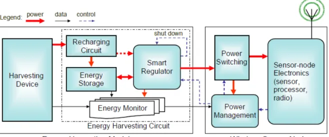
Differing from battery-powered sensors, the energy harvesting device should be designed with high efficiency, which converts, collects, and stores the energy to power the sensor node as needed, as shown in Fig. 1.221, an energy harvesting wireless sensor has a complicated architecture including an energy harvesting module with harvesting device unit and energy harvesting circuit unit. To establish a congruent interface with the energy harvesting module, two additional submodules, power switching and power management modules, are integrated within the wireless sensor node.
Fig. 1.2 General structure of an energy harvesting module and compatible wireless sensor nodes.21
The harvesting device generates usable electrical energy from ambient energy. It can be implemented by two mechanisms: one is based on materials for energy conversion such as piezoelectric material, electrostrictive material, pyroelectric material, thermoelectric material , solar cell, etc.; the other relies on structures for energy conversion such as electromagnetic
harvesters and electrostatic harvesters. Unlike battery supply, which is simply characterized by the amount of residual and reliably available energy, the characterization of environmental energy is time-dependent and more complicated, also, the environmental energy has the potential to be used permanently.
1.3 Summary of Potential Energy Sources and the
corresponding technique
This part examines the potential ambient energy sources and current methods of harvesting electrical energy.
1.3.1 Solar Energy
Solar or other light energies can be converted into electrical power using solar cells, which are commercially mature and well characterized. On average, the earth’s surface receives about 1.2×10¹⁷ W of solar power. It means that in less than one hour enough energy is supplied to satisfy the entire energy demand of the human population22. Photovoltaics is a method of generating electrical power by converting solar radiation into direct electrical current using semiconductors that exhibit the photovoltaic effect. It is well known as generating electric power by using solar cells.
Solar power has large potential for power generation due to the large input power from the sun, but many challenges limit its practical use. Different materials display different efficiencies and have different costs. The output energy depends on the material which must have characteristics matched to the spectrum of available light, for example, crystalline materials such as silicon and gallium arsenide have moderated absorption efficiency and high conversion efficiency about 15% ~ 30%; while thin film materials such as cadmium telluride have high absorption efficiency and lower conversion efficiency (≤10%). The choice of materials also relies on its spectral response and the light source of interest23.
Outdoor isolation levels offer approximately two to three orders of magnitude more electricity per unit area than indoor electric light sources12,17,20. Measurements taken in normal office lighting show that only 6 μW/cm3 can be converted by a solar cell12, which is not nearly enough for the targeted application under consideration and restricts its main use to areas where there is not enough sunlight. Therefore, using other techniques of harvesting energy such as vibration and thermal is suitable.
1.3.2 Radio Frequency Energy
Radio frequency energy is emitted by sources that generate high electromagnetic fields such as TV signals, satellites orbiting earth, wireless radio networks, wifi and cell phone towers. We are being bombarded with energy waves every second of the day. If it could be possible to gather the energy and store it, we could potentially use it to power other circuits.
Most commonly used as an application for radio frequency identification tags in which the sensing device wirelessly sends a radio frequency to a harvesting device which supplies just enough power to send back identification information specific to the item of interest (Fig.
1.3).
Fig. 1.3 RFID System Diagram. (http://www2.egr.uh.edu/~mpark5/rfid.html)
RF energy harvesting needs a receiving antenna linked to a power generating circuit capable of converting AC voltage to usable DC voltage24, as shown in Fig. 1.4. Although the total energy is fixed, RF antenna designs and the distance between the source and the device can vary the energy density. The increased concentration of RF energy by focusing is typically measured in terms of antenna efficiency. The efficiency of an antenna is related to the shape and impedance of the antenna and the impedance of the circuit. If the two impedances aren’t matched then there is reflection of the power back into the antenna meaning that the circuit was unable to receive all the available power.
Fig. 1.4 Overview of a RF energy harvesting system. (http://www.sensorsmag.com)
1.3.3 Human Power
Human power is defined as the use of human motion or body heat for energy generation to power an electronic device. That said, power might be scavenged indirectly from the user’s everyday actions or might be intentionally generated by the user. The energy can be harvested from body heat, breathing, blood pressure, typing, arm motion, pedaling, and walking, Table
1.3 provides a perspective on the amount of power used by the human body during various
activities25. In general, most attraction is focusing on two fields about human power for energy harvesting: human motion and body heat.
Table 1.3 Human energy expenditures for selected activities.25
1.3.4 Vibration Energy
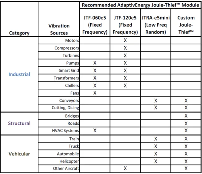
Vibration energy harvesting is one approach where energy from parasitic vibrations can be converted into electrical energy by using piezoelectric or electromagnetic transducers. Parasitic vibrations come from a range of sources around the energy harvesting device, such as wind, seismic forces and traffic26. There are three main categories of vibration sources, as shown in Table 1.4 Industrial, Structural, and Vehicular27. Existing approaches to vibration energy harvesting typically utilize a rectifier circuit, which is tuned to the resonant frequency of the harvesting structure and the dominant frequency of vibration.
Vibration energy harvesting techniques can rely on electromagnetic (inductive), electrostatic (capacitive), piezoelectric, and magnetostrictive approaches. Four common techniques will be discussed individually, and then a comparison table will be drawn to compare the features of different techniques.
Table 1.4 Categories of vibration and recommended Adaptivenergy Joule-ThiefTM energy harvesting module.27
1.3.4.1 Electromagnetic Energy Harvesting
Since it is quite easy to keep a strong magnetic field with a permanent magnet, electromagnetic vibration-power generators are preferred in many applications. The basic electromagnetic energy generator consists of a mass mounted on a spring which vibrates relative to housing when subjected to an external vibrational force. The mechanical energy of the moving mass is transformed to electrical energy by having the mass move a magnet relative to a coil. The motion of such a system can be described as Fig. 1.5 (a)28. Faraday’s Law is a basic principle of electromagnetic system to operating principals of electric generator, as illustrated in Fig. 1.5 (b)29.
(a) (b)
Fig. 1.5 (a) Schematic diagram of electromagnetic generator. m - mass, k- spring D – damping, (b) the principle of operation of electromagnetic transducer.29
Electromagnetic-based generators have been demonstrated to generate power levels ranging from 0.3 to 800 µW from vibration frequencies of several hundred hertz. Williams and Yates proposed an electromagnetic energy harvesting device in 199630, the power they produced was proportional to the cube of the vibration frequency. For a typical device, the power generation was 1 μW at 70 Hz and 0.1 mW at 330 Hz. In order to maximize power generation, the mass deflection should be as large as possible. Glynne-Jones et al. presented that the output voltage is a function of vibration amplitude as well as its magnetic field strength. They designed the electromagnetic generator which can produce a peak power of 3.9mW with an average power of 157 µW when mounted on the engine block of a car31. However, due to low electromagnetic damping, the size and structure of the device, the optimization theory is difficult to be verified in practice.
In 2006, Chitta Ranjan Saha et al.28 presented a model for an electromagnetic-based, vibrational power generator and investigated the optimum condition for electromagnetic damping and local resistance. Furthermore, they also verified the optimum condition by using measurements on two macrogenerators which have been built and tested. Their result showed that the power is maximum for the value of load resistance at which electromagnetic damping and parasitic damping are equal. The electromagnetic damping is always much less than the parasitic damping and the power is maximized for a load resistance equal to the coil resistance.
In 2009, Ibrahim Sari et al.32 proposed a new electromagnetic micro energy harvester, employing array of parylene cantilevers on which planar gold coils are fabricated. The micro
harvester generates voltage by virtue of the relative motion between the coils and a stationary magnet. The fabricated device occupies a volume of 9.5 × 8 × 6 mm3. A single cantilever of this device can generate a maximum voltage and power of 0.67 mV and 56 pW, respectively, at a vibration frequency of 3.4 kHz. These values can be improved considerably by increasing the coil turns and natural frequency of the cantilevers.
In summary, the electromagnetic energy conversion mechanism is simple without the need of smart materials, but it has relatively larger volume than the other vibration energy conversion system (e.g., piezoelectric energy conversion), because of the required permanent magnets and pickup coil. Due to its inductive property, comparatively high output current levels are achievable at the expense of low voltage. Voltage multiplier may be a suitable solution to increase the voltage level.
1.3.4.2 Electrostatic Energy Harvesting
An electrostatic transducer uses the force between charges stored on electrodes to couple the energy from the mechanical domain into the electrical domain. By placing charge on the capacitor plates and then moving the plates apart, mechanical energy can be converted into electrical energy which can then be stored and utilized by a load as depicted in Fig. 1.633.
Fig. 1.6 Schematic of a typical electrostatic harvester vibrating horizontally.33
Meninger et al.34 presented an electrostatic generator that employs a variable micromachined capacitor. Fundamentally, electrostatic harvesters harness the work ambient vibrations exert on the electrostatic force of a variable capacitor (i.e., varactor). In more
physical terms, vibrations cause the gap distance and/or overlap area of a parallel-plate capacitor (CVAR) to vary with a net effect, under constant charge or voltage conditions, of producing electrical energy35. Two possible energy conversion cycles in the charge-voltage plane for the MEMS transducer are charge constrained conversion and voltage constrained conversion, respectively. Fig. 1.7 illustrates the process of charging and discharging the capacitance following the constant charge (path A-B-D-A) or constant voltage (path A-C-D-A) approaches34. The energy enclosed by the total path is the energy harvested in the cycle. One basic constraint for both cycles is that there is some maximum allowable voltage, Vmax, which is set by some process or system requirement.
Fig. 1.7 Scheme of electrostatic energy conversion cycle.34
Fig. 1.8 (a) and (b) illustrate the principle of operation of the two possible electrostatic
energy conversion29, respectively. The name of the path depicts which property is held constant during the conversion process while the other changes in response to a varying capacitance. If the charge on the capacitor is maintained constant while the capacitance decreases (e.g., reducing the overlap area of the plates or increasing the distance between them), the voltage will increase, operation as Fig. 1.8 (a). If the voltage on the capacitor is maintained constant while the capacitance decreases, the charge will decrease, operation as
Fig. 1.8 Principle of operation of electrostatic transducer. (a) charge constrained (b) voltage constrained.29
The electrostatic energy harvesting does not require smart materials and could be interested on MEMS. Due to capacitive-based device, it generates relative high voltage of 2~10 V and results in a limited current-supplying capacity33. Meninger et al.34 compared two different conversion cycles using a variable capacitor under the condition of constant maximal applied voltage. In 2004, Roundy et al. optimized the electrostatic harvester and improved the output power density up to 110 µw/cm3 at 120 Hz vibration33.
1.3.4.3 Piezoelectric Energy Harvesting
The piezoelectric effect is a phenomenon whereby a strain in a material produces an electrical charge in that material, and conversely an applied electric field produces a mechanical strain36 as shown in Fig. 1.9. It was discovered by Jacques and Pierre Curie in 1880. Curie’s brothers found that certain materials, when subjected to mechanical strain, suffered an electrical polarization that was proportional to the applied strain. This is the piezoelectric effect used for mechanical to electrical energy conversion (Fig. 1.929).
Piezoelectric energy is the most popular among all these vibration-based methods because of reasonable electro-mechanical coupling coefficient, no bulky accessories (such as coil or permanent magnet), and feasibility of being deposited on substrates for MEMS application. Concept of utilizing piezoelectric material for energy harvesting has been studied by many researchers. Umeda et al.37 investigated fundamentals of piezoelectric generator using a piezoelectric vibrator and a steel ball. This study quantified the energy produced when a steel ball impacted a thin piezoelectric plate. The authors used an equivalent circuit model to predict the energy while modifying numerous parameters in the system to find the best combination. It was determined that the efficiency increased if the mechanical quality factor increased, the electromechanical coupling coefficient increased and the dielectric loss decreased. The maximum efficiency of 52% could be obtained by simulation. Elvin et al.38 used a polyvinylidene fluoride (PVDF) piezofilm sensor attached to a simply-supported Plexiglas beam to generate electric power. The goal of this energy harvesting experiment was to generate sufficient energy from the strain induced on the piezofilm by the bending beam to power a telemetry circuit. The energy generated from the PVDF patch was accumulated in a capacitor. A switch was added to the circuitry to allow the capacitor to charge or discharge, which produced the output voltage range of 0.8~1.1 V for a RF transmitter.
Other types of piezoelectric materials were also investigated for power harvesting purposes39. The two types being the commonly used monolithic piezoelectric (PZT) bimorph and Macro Fiber Composites (MFC), both transducers were used to charge nickel metal hydride batteries of varying sizes to compare their performance and ability to store electrical power. It was found that the MFC produced a much higher voltage while the current remains far smaller than that of the PZT. Because the use of interdigitated electrodes in the MFC limited the amount of current produced, and hence hindered its capabilities as a power harvesting device for charging batteries. The PZT, however, was able to charge 40 mAh and 80 mAh batteries within two hours. It was also shown that charging a battery by vibrating the PZT at resonance typically took less time than by using a random input signal to the PZT.
While significant headway has been made in the field of energy harvesting, the energy generated from piezoelectric material is still not sufficient to power the desired electronic systems. To dynamically optimize the power transfer efficiency, Ottman et al.40 presented an adaptive approach to harvest electrical energy from a mechanically excited piezoelectric element. The harvesting circuit consists of an ac–dc rectifier with an output capacitor, an electrochemical battery, and a switch-mode dc–dc converter that controls the energy flow into
the battery. It was found that the power output could be increased by over 400% using the adaptive dc–dc converter. To further investigation, they continued their work using a similar circuitry41, but modified it by removing the adaptive circuitry and used a fixed switching frequency. With this circuit, the power flow was increased by over a factor of 3 at a peak resonant excitation level of 70 V open circuit. Additionally, the efficiency of 70% at an optimal value of excitation was obtained.
Recently, Guyomar et al.42-43 proposed a new approach for piezoelectric energy reclamation from mechanical vibrations, which is called “Synchronized Switch Harvesting on Inductor” (SSHI) by using a self-adaptive power harvesting circuit. Fig. 1.10 shows (a) the model of vibrating structure including a piezoelectric element and (b) the SSHI energy harvesting device in steady state operation. This approach is derived from a popular method called ‘Synchronized Switch Damping on Inductor’ (SSDI)44, a semi-passive technique that was developed to address the problem of vibration damping in mechanical structures. It consists in the switching sequence triggered on the maximal and minimal of the piezo mechanical displacement. It is shown that the SSHI technique increases the harvested power by a factor 8 compared to the standard technique42.
(a) (b)
Fig. 1.10 (a) model of vibrating structure including a piezoelectric element (b) SSHI energy harvesting device in steady state operation.
1.3.4.4 Magnetostrictive Energy Harvesting
Magnetostrictive materials (MsM) are a class of compounds which change their shape or dimension when they are subjected to a magnetic field. The reciprocal effect, vibration-induced strain of a MsM producing a change in the magnetization of the material, is called Villari effect. The mechanism of magnetostriction can be depicted by Fig. 1.11. The principle of vibration energy harvesting is mainly based on Villari effect.
Fig. 1.11 Mechanism of magnetostriction
(
http://aml.seas.ucla.edu/research/areas/magnetostrictive/mag-composites/Magnetostriction%20and%20Magnetostrictive%20Materials.htm)
To convert ambient vibrations to electrical energy, current technology focuses mainly on piezoelectric materials, but its inherent limitations including aging, depolarization, brittleness, and high output impedance confine further applications in actual wireless sensor networks. To overcome such limitations, magnetostrictive materials (MsM) would be a promising candidate as depicted in Fig. 1.1221. It utilizes the Villari effect of magnetostrictive, where vibration induced strain from a MsM produces a change in the magnetization of the material. This change in magnetization is converted into electrical energy using a pick-up coil or solenoid surrounding the MsM according to Faraday’s law.
Fig. 1.12 Prototype of MsM energy harvesting device.21
Staley and Flatau attempted to apply a Terfenol-D alloy in vibration energy harvesting45. The Terfenol-D rod was operated in axial mode rather than flexural bending mode. The maximum output power was up to 45 μW at resonant frequency of 45 Hz, and the amplitude of AC output voltage was less than 0.35 V which was inapplicable to voltage rectification.
Wang and Yuan46 firstly proposed the feasibility of using amorphous metallic glass (Metglas 2605SC) as MsM for harvesting energy from ambient vibrations. Compared to piezoelectric materials, Metglas-based harvesters displays more competitive due to its
ultra-high magnetomechanical coupling efficiency (>0.9), ultra-higher Curie temperature, and no depolarization problem. However, it has relatively large dimension, which is hard to be integrated with MEMS, because of the pick-up coil and permanent magnets.
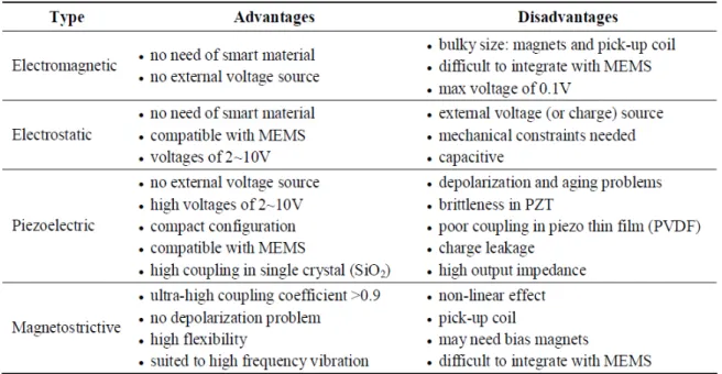
1.3.4.5 Comparison of different vibration energy harvesting techniques
Electromagnetic, electrostatic, piezoelectric and magnetostrictive are four main energy harvesting mechanisms from ambient vibration. Each of the technologies described above has their own advantages and disadvantages and these are now summarized as in Table 1.521. Currently, piezoelectric, or PZT, is the most popular material because of its compact configuration and compatibility with MEMS (Micro-Electro-Mechanical System), but its inherent limitations including aging, depolarization, brittleness, and high output impedance confine further applications in actual wireless sensor networks.
Table 1.5 Summery of the comparison of the different vibrational types of harvesting mechanisms.21
1.3.5 Thermal Energy
Thermal energy is the other form of energy readily presenting in environment. Thermal energy harvesting devices could use thermal energy of different sources: persons and animals, machines or other natural sources. The search for an efficient way to convert thermal into useful electrical energy has been ongoing for decades. Ambient thermal energy commonly
these two representations of thermal energy, majority attempts to generate electrical energy from heat mainly rely on two effects: thermoelectric effect and pyroelectric effect.
1.3.5.1 Thermoelectric Energy Harvesting
Semiconductor thermoelectric generators, which convert thermal energy to electrical energy, have been of great interest in recent years. Due to their merits, such as high reliability, silence, together with their capability of utilizing waste heat as an energy source make them an attractive way for energy harvesting from temperature gradients.
1.3.5.1.1 Global Conception of Thermoelectric Effect
Thermoelectric phenomena (often known simply as thermoelectric effects) encompasses three separately identified effects: the Seebeck effect, Peltier effect and Thomson effect. All of these three effects are thermodynamically reversible.
The Seebeck effect shows that an electrical current is present in a series circuit of two dissimilar metals, provided the junctions of the two metals are at different temperatures, as shown in Fig. 1.13 (a).This was because the metals responded differently to the temperature difference, creating a current loop and a magnetic field.
Fig. 1.13 Diagram of (a) Seebeck effect, (b) Peltier effect and (c) Thomson effect. (http://www.daviddarling.info/encyclopedia/S/Seebeck_effect.html)
The Peltier effect is the presence of heat at an electrified junction of two different metals, Peltier found that the junctions of dissimilar metals were heated or cooled, depending upon the direction in which an electrical current passed through them, as shown in Fig. 1.13 (b). The Peltier effect can be used to create a refrigerator which is compact and has no circulating fluid or moving parts. The Thomson effect describes that an electromotive force (emf) would arise within a single conductor whenever a temperature gradient was present (Fig. 1.13 (C)).
In summary, these three effects are not independent of, but is rather a combination of each other.
1.3.5.1.2 Global Conception of Thermoelectric Energy Harvesting
The thermoelectric effect is the ability to convert thermal heat flow to an electric current proportional to the heat flow based on Seebeck effect. Both cooling and energy harvesting are possible. A thermoelectric device creates a voltage when there is a different temperature on each side. Conversely when a voltage is applied to it, it creates a temperature difference.
Thermoelectric modules are the main way for energy harvesting from temperature. These are based on temperature gradients leading to heat flow through the thermoelectric generator and a small percentage of the heat flow is converted to electric energy.
Traditional thermoelectric systems are comprised of a number of doped semiconductor elements arranged electronically in series and thermally in parallel as shown in Fig. 1.14. If heat is flowing between the top and bottom of the thermoelectric device (forming a temperature gradient) a voltage will be produced and hence an electric current will flow.
Fig. 1.14 Thermal-to-electric conversion with thermoelectrics. (http://www2.electronicproducts.com/)
A thermoelectric converter is a heat engine and like all heat engines it obeys the laws of thermodynamics. If we first consider the converter operating as an ideal generator in which there are no heat losses, the efficiency is defined as the ratio of the electrical power delivered to the load to the heat absorbed at the hot junction. For a given temperature difference, the conversion efficiency, which is limited by the material properties, may be obtained using47.
2 1 ZT 1 1
θ θ
where θ2 and θ1 are temperatures at hot and cold ends of the converter, and ZT is figure of merit. Fig. 1.15 depicts the figure-of-merit of a number of thermoelectric materials together with potential generating applications48.
Fig. 1.15 Figure-of-Merit of a selection of materials.48
Material properties are the key parameter for improving both the output power (the increase of the thermal heat flow thus making it difficult to keep the temperature gradient) and the efficiency (improving the Seebeck coefficient and figure of merit).
However, when considering the limited heat exchange on the outer surfaces of the thermoelectric module, it was found that figure of merit does not really express the performance of a thermoelectric generator49. Apart from Seebeck effect and thermoelectric generator design, parameters such as the heat loss of the Joule and Peltier effects caused by the electric current largely affect the performance. This is due to the fact that a limited heat exchange on the outer surfaces results in a decrease of the actual temperature gradient and thus makes the Joule and Peltier effect much more important in the performance loss than what could be expected from the single figure of merit.
1.3.5.1.3 Evolution of Thermoelectric Energy Harvesting
Thermoelectric technology has been used for capturing ambient energy practically in wide areas recently. Wu et al50 (1996) proposed the concept of a waste-heat thermoelectric generator, the specific power output of the generator was analyzed and compared with that of Carnot. They concluded that a completely reversible heat engine played a major role in the development of the performance of thermoelectric generators.
Rowe et al.51 investigated the ability to construct a large thermoelectric generator capable of supplying 100 watts of power from hot waste water. The system tested used numerous thermoelectric devices placed between two chambers, one with flowing hot water and the other with cold water flowing in the opposite direction, thus maximizing the heat exchange. With a total of 36 modules, each with 31 thermocouples, 95 watts of power could be generated. Attempts are also being made to improve the competitiveness of thermoelectrics by increasing the electric power factor. In 2002, Rowe et al52 synthesized intermediate valence compound YbAl3. At temperatures below 100 K, the electrical resistivity exhibits a ρ(θ) = ρ0 + Aθ 2 dependence, the Seebeck coefficient exhibits a temperature dependence. Combination of a large Seebeck coefficient and low residual resistivity of single crystalline YbAl3 leads to the appreciable electrical power factor of 340 × 10-6 W cm-1K−2 at 80 K.
Stordeur et al.53 developed a low power thermoelectric generator (micro-thermoelectric harvester) capable of generating tens of microwatts of power (15 μW/cm2 from a 10°C temperature differential) out of a device that had previously generated nanowatts with the same size. The device was based on thin film thermoelectric materials, consisted of 2250 thermocouples, and operated in temperatures ranging from room to not higher than 120°C. Fleming et al.54 investigated the use of thermoelectric generator (TEG) for powering microscale air vehicles. The idea is to integrate the TEGs as part of the airframe powerplant assembly to reclaim a portion of the engine’s waste heat as electric power. A TEG was mounted on the exhaust system of an internal combustion engine that was shown to generate 380 mW of power.
The oil consumption of road transportation is one of the major issues in the world,
automotive engines reject a considerable amount of energy to the ambience through the exhaust gas. The latest statistics indicates there is only about 25% of the fuel combustion energy is utilized for vehicle operation whereas about 40% is lost in the form of waste heat of
exhaust gas. Significant reduction of engine fuel consumption could be attained by recovering
of exhaust heat by using thermoelectric generators. Several research groups have studied the use of thermoelectric generators for obtaining waste energy from the exhaust of automobiles. Wojciechowski et al 55 designed and tested a prototype thermoelectric generator mounted on self-ignition (Diesel) engine. The designed model was able to recover even 25 kW of heat energy. Assuming the 5% efficiency of the thermoelectric modules it could allow to obtain the maximum electric power of app. 750 W. This power is comparable to the power of typical alternators used in cars with 1.3 dm3 engine capacity. Birkholz et al.56 fitted a TEG unit
circuit voltage of 22 V and a total power of 58 W. Similarly, Matsubara57 constructed an exhaust system using ten TEG modules and a liquid heat exchanger to maximize the thermal gradient. The system was tested on a 2000 cc class automobile and shown to produce 266 W of power.
Sodano et al3 proposed a novel approach to thermal harvesting using a small greenhouse device to capture thermal energy from solar radiation. To increase the amount of thermal radiation captured by the power harvesting device, the hot side of the thermoelectric generator is placed in a small greenhouse, while the cold side is secured against a thermal sink.
Latest advancement in preparing new thermoelectric materials with good performance has made it available to fabricate feasible micro-generator. The most reported researches about thermoelectric micro-generators have been focusing on miniaturizing n-legs and p-legs in the micro-devices and the smallest size has already reached micrometer scale. But the properties of the thermoelectric material used in this form are almost the same as that in bulk. It has been verified by theory and experiments that the nanowires of thermoelectric material should have an enhanced figure of merit due to the quantum- size effects. Wang et al. have been successfully prepared one-dimensional n-type and p-type Bi2Te3 nanowire arrays by electrochemical deposition (ECD) technology. Based on those work, a new type of thermoelectric micro-generator comprised of n-type and p-type nanowire array was designed. This micro-generator can be used as not only an independent power generator, but also can be integrated with electric components together to convert waste heat into electric power.
In 2010, The National Institute of Advanced Industrial Science and Technology (AIST) publish news through their official website, a thermoelectric power generation module has been developed using new materials. The module has been demonstrated to have power generation performance equivalent to that of existing thermoelectric power-generation modules, with an output power of 1.7 W and a generation efficiency of about 4% for a temperature difference of 300°C (330°C on the hot side of the module and 30°C on the cold side).
1.3.5.1.4 Summary
According to the study of thermoelectric generator, it is found that with relatively small thermal gradients and only conductive heat transfer, a thermoelectric generator can be used for energy harvesting applications. In conclusion, the advantages of thermoelectrics as following:
1. No moving parts allow continuous operation for many years. 2. Thermoelectrics contain no materials that must be resupplied. 3. Heating and cooling can be reversed.
Thermoelectric energy conversion suffers from its low efficiency (currently less than 10%). The development of materials that are able to operate in higher temperature gradients, and that can conduct electricity well, without conducting heat, will result in increased efficiency. In brief, the generated voltage and power is proportional to the temperature differential and the Seebeck coefficient of the thermoelectric materials. Large thermal gradients are necessary to produce practical voltage and power level. Nevertheless, temperature differences greater than 10°C are rare in a micro-system, consequently producing low voltage and power level.
1.3.5.2 Pyroelectric Energy Harvesting
Pyroelectric energy conversion offers a novel and direct solution to convert waste heat into electricity by alternatively heating and cooling a pyroelectric material resulting in electricity generation. Contrary to the thermoelectric generator, pyroelectric materials do not need a temperature gradient, but time temperature fluctuations, thus the application targets are quite different.
1.3.5.2.1 Global Conception of Pyroelectric Energy Harvesting
Pyroelectricity is the ability of certain materials to generate an electrical charge when they are heated. The temperature variation slightly modifies the position of the atoms within the crystal structure, such that the polarization of the material changes. This polarization change creates a voltage across the material. This property was discovered before piezoelectric effect and is mainly used for pyroelectric infrared temperature sensor. Recently, it is found that it could be also used for the conversion of heat directly into electrical energy.
The pyroelectric effect can be used in a power generation system to force electrical charge from the pyroelectric material to an electrical storage device via heating. Subsequently, the electrical storage device can be used to satisfy the power demands of an electromechanical device.
Pyroelectric effect can be considered as the inverse electrocaloric effect. The electrocaloric effect is enhanced in the vicinity of a transition like
antiferroelectric-near a transition. Materials with high pyroelectric activity or those exhibiting a transition are always corresponding to larger polarization variations, thus it can be used to greatly increase the harvested energy.
The advantages of pyroelectric energy conversion are two-fold. First, it does not require the high source temperatures that a traditional thermoelectric power generator requires. Time varying temperature changes are necessary. Second, the combination of relatively low operating temperatures and almost no moving parts provides the potential for a power generating system with excellent reliability and a long lifetime.
1.3.5.2.2 Evolution of Pyroelectric Energy Harvesting
Pyroelectric power generation has been studied by a small number of researchers since the late 1950’s. The feasibility of direct conversion of heat into electrical energy with ferroelectric materials was proposed in 195958 and widely reviewed59-60. Initial investigations of the principles of the conversion of heat energy directly into electrical energy were made by Clingman & Moore61, Childress62 and Hoh63. They studied the theoretical performance of ferroelectric materials operated in the neighbourhood of its Curie point (a molecular realignment phenomenon that is a strong function of temperature)62. Additionally, they determined the basic dielectric material properties necessary for meaningful power generation, e.g., a very large electric displacement, a very large breakdown voltage, and a strong temperature dependence of the electric displacement. The electric displacement is the amount of electrical charge that a dielectric material can store per unit surface area, and the breakdown voltage is the point at which the dielectric material suffers catastrophic failure (destruction of the charge storing capability). The product of these two properties describes the electrostatic energy density of the dielectric material, and this must be sufficiently large to extract significant quantities of electrical energy. A strong temperature dependence of the electric displacement is necessary to maximize the electrical charge that can be extracted from the dielectric material when it is heated and cooled.
In the mid 1960’s, Fatuzzo et al64 studied the efficiency for power converter by using of several different types of power generation cycles. They calculated and compared the thermal and electrostatic energy stored by their pyroelectric materials, as well as evaluate the performance of the power generation cycles by determining the thermodynamic states of their materials.
Gonzalo tackled the field of pyroelectric power generation in the mid 1970’s65, he concluded that with proper material selection, a pyroelectric power generator that used only one pyroelectric material could achieve a maximum efficiency of 4%, which corresponds to 17% of the Carnot efficiency. Additionally, Gonzalo proposed that several of these pyroelectric devices could be tailored to operate in sequential temperature ranges, such that they could be connected, creating a multistage converter. This device has a much larger temperature range of operation, increasing the maximum predicted efficiency to 14%, for a device operating between 300 and 1500 K.
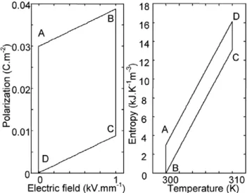
A large advancement was obtained in the field of pyroelectric conversion by Olsen’s group66-68. They proposed the first pyroelectric conversion cycle named ‘Olsen cycle’ or ‘Ericsson cycle’ (electric analogous of the Ericsson heat engine cycle). They measured this thermodynamic cycle in terms of charge-voltage (polarization versus applied electric field) behavior on a new materials -- copolymer P(VDF-TrFE). Between 23 and 67°C, each conversion cycle was able to generate 30 mJ/cm3 of output electric energy density by applying maximum electric field 55 kV/mm67. Following this method, they also patented a pyroelectric power generator by the use of one or more capacitors having temperature dependent capacitance69-70. Olsen’s group built, tested, and subsequently patented an experimental pyroelectric power generator that demonstrated the heat cascading effect in a pyroelectric device, shown in Fig. 1.1671. In this schematic, the ceramic stack consists of thin film materials separated by a working fluid, which is oscillated by the pump drive. The difference in temperature between the heater and the cooling unit induces temperature oscillations in the flow, which, in turn, generate temperature oscillations in the dielectric materials, providing the heating and cooling necessary for power generation.
Fig. 1.16 Schematic View of the Thermal-Mechanical Portions of the Pyroelectric Conversion Experiment.71
Tiway72 carried out experiments with thin film ferroelectric polymers polyvinyledene (PVF2), attempting to quantify the maximum ratio of thermal to electrical energy conversion, as well as relate the performance of his ferroelectric material to other materials. The energy ratio, i.e. the ratio of the input heat energy to the obtainable electrical energy is assessed to be around 0.861. Most recently, Ikura’s73 experimental investigation implemented one of Olsen’s theoretical operating cycles in a simple pyroelectric converter, demonstrating the ability to generate significant quantities of high voltage power of 15-52 mJ/cm3 with a pyroelectric device. However, Ikura’s device was highly inefficient, the ratio of electrical output to electrical input ranged between 1.2~1.5.
Entering the 21st century, significant breakthrough have been made in the framework of the pyroelectric energy conversion benefiting from the study on pyroelectric effect of materials, including linear pyroelectric effect and nonlinear pyroelectric effect (FE-FE and FE-PA phase transition) respectively.
First of all, utilizing linear pyroelectric effect, Guyomar et al74 investigated the feasibility of heat energy harvesting on PVDF film combining with the synchronized switch harvesting on inductor (SSHI) technique. For amplitude variations of temperature from 0.5 to 8 K, the conversion efficiency is found about 0.02% of Carnot thermodynamic cycle with a standard interface, and the SSHI technique increases the converted energy by a factor which is about 2.5 times of the standard interface. The produced electrical power for temperature amplitude 7 K is more than 0.3 mW for an energy harvesting device composed for 8 g of active material. Sebald et al75 also simulated the pyroelectric energy harvesting using linear pyroelectric properties of 0.75Pb(Mg1/3Nb2/3)O3-0.25PbTiO3 ceramic. They studied the output power as a function of the heat exchange coefficient for 20°C peak-to-peak temperature variation. Neglecting dielectric losses, increasing the heat exchange or frequency of temperature variation results in an increase of the harvested power. In addition, they estimated the output power under the same simulated conditions for different pyroelectric materials: linear and nonlinear as in Table 1.6.