HAL Id: tel-03144377
https://tel.archives-ouvertes.fr/tel-03144377
Submitted on 17 Feb 2021HAL is a multi-disciplinary open access
archive for the deposit and dissemination of sci-entific research documents, whether they are pub-lished or not. The documents may come from teaching and research institutions in France or abroad, or from public or private research centers.
L’archive ouverte pluridisciplinaire HAL, est destinée au dépôt et à la diffusion de documents scientifiques de niveau recherche, publiés ou non, émanant des établissements d’enseignement et de recherche français ou étrangers, des laboratoires publics ou privés.
Bharath Reddy Adapa
To cite this version:
Bharath Reddy Adapa. The application of wavefront sensing methods to optical surface metrology. Instrumentation and Detectors [physics.ins-det]. Université Grenoble Alpes [2020-..], 2020. English. �NNT : 2020GRALY032�. �tel-03144377�
i
This dissertation is the result of my own work and includes nothing, which is the outcome of work done in collaboration except where specifically indicated in the text. It has not been previously submitted, in part or whole, to any university of institution for any degree, diploma, or other qualification.
Signed:_______ADAPA Bharath Reddy______________________
Date:_________18/01/2021_______________________________
Bharath Reddy ADAPA,
PhD student, ESRF / Imagine Optic,
ii
A
BSTRACT
Synchrotrons are quite a recent development in the history of science but have seen tremendous improvements since their inception in middle of 20th century. Synchrotrons provide X-rays with very high brilliance generally many orders of magnitude larger than X-ray tube sources and thus require very high quality optics for their operations. X-ray mirrors of different sizes (10 mm – 1500 mm lengths) and different shapes (flat, spherical, elliptical, toroidal…) are some of the most commonly used optics at the synchrotron facilities. The mirrors should be highly polished with surface figure errors often <1 nm rms to maintain the beam quality and require sophisticated metrology instruments for both mirror manufacturing and quality control. Synchrotron mirror metrology instrumentation has evolved in parallel to the increasing quality demands and the most commonly currently used instruments for such applications are Long Trace Profilers (LTP), Nanometer Optical Component Measuring Machines (NOM), Fizeau interferometers, and Micro interferometers. The Stitching Shack-Hartmann wavefront sensor (SHARPeR) is a relatively new addition to the synchrotron mirror metrology instruments. It is a 2D slope measuring instrument developed by Imagine Optic and Q-Sys and is available as a complete commercial product. SHARPeR uses subaperture stitching algorithms to measure synchrotron mirrors which are typically larger than most of the optical metrology instrument apertures.
The initial SHARPeR instrument presented problems for the accurate measurement of long and/or highly curved mirrors and my PhD focused primarily on improving the performance of the system. The SHARPeR instrument installed at the ESRF has been validated using other ESRF instruments such as LTP, Fizeau and Micro- interferometers for performance qualification and for insights into the types of errors displayed by SHARPeR. Different types of systematic and random errors have been studied which include errors from CCD detector (of the wavefront sensor), SHARPeR head optical aberrations, translation errors and environmental errors. Instrument errors such as retrace errors are shown to be a significant limit to the accuracy of measurements of highly curved mirrors by SHARPeR. New measurement techniques have been developed which showed significant improvement in the accuracy of slope errors and figure errors for such mirrors. The SHARPeR instrument has also been calibrated for retrace errors with mirror tilt using a standard Michelson interferometer and improved calibration methods have
iii
allowed improvements in measured shape parameters such as radius of curvature. Environmental effects during measurements such as thermal fluctuations and air turbulences were shown to be major influence in degrading the accuracy of measurements of long mirrors. Instrument design has been improved in many iterations to insulate the optical path and to avoid heat sources near the measurement path. Measurement speed has been improved using ‘on the fly’ scanning method which also reduces long term drift influences from the environment.
SHARPeR uses a proprietary stitching software StitchWave provided by Imagine Optic. As an alternative offering more flexibility, a new open source stitching software (PyLOSt) has been developed to stitch measurements from various instruments including SHARPeR. Different stitching algorithms have been developed to stitch 2D slope and height data scanned along one axis (1D), such as Progressive Stitching (PROG), Matrix overlap error (MO) and global optimization (GO). Algorithms to extract reference errors within the stitching process have also been implemented. The performance of stitching algorithms has been tested using synthetic SHARPeR and Fizeau datasets and has provided satisfying results. PyLOSt has been used for most of the SHARPeR measurements presented in this thesis manuscript.
iv
R
Le développement des synchrotrons est relativement récent dans l'histoire de la science, cependant ces instruments ont connu d’importantes améliorations depuis leur création au milieu du 20e siècle. Les synchrotrons fournissent des rayons X avec une brillance très élevée généralement supérieure de plusieurs ordres de grandeurs comparée aux sources de rayons X à tube et nécessitent donc des optiques de très haute qualité pour leur opération. Les miroirs à rayons X couramment utilisés dans les installations synchrotron offrent une grande diversité de tailles (longueurs de 10 mm à 1500 mm) et de formes (plans, sphériques, elliptiques, toroïdales…). Leur surface optique doit répondre à des critères de polissage de très haute qualité avec des erreurs de forme souvent <1 nm afin de conserver la qualité du faisceau ce qui implique des instruments de métrologie de pointe pour assurer leur fabrication et garantir le contrôle qualité. L’instrumentation pour la métrologie des miroirs synchrotrons a évolué pour répondre aux exigences de qualité croissante et les instruments les plus couramment utilisés pour ces applications sont les profilomètres optiques tels que le LTP (Long Trace Profiler) ou le NOM (Nanometer Optical Component Measuring Machines), des interféromètres de type Fizeau ou encore des micro-interféromètres. Le capteur de front d’onde nommé SHARPeR (Stitching Shack-Hartmann wavefront sensor) est venu s’ajouter récemment à cette liste. Il s'agit d'un instrument de mesure de pentes 2D développé par Imagine Optic et Q-Sys, disponible en tant que produit commercial complet. Le SHARPeR utilise des algorithmes de recollement de sous-pupilles pour mesurer des miroirs synchrotrons dont la longueur excède l’ouverture de la plupart des instruments de métrologie optique.
L'instrument SHARPeR ayant révélé des problèmes de précision lors de la mesure de miroirs longs et/ou fortement courbés, ma thèse s'est donc principalement orientée sur l'amélioration des performances du système installé à l’ESRF. Ces dernières ont été évaluées à l’aide des autres instruments du laboratoire de métrologie de l’ESRF tels que le LTP, l’interféromètre de Fizeau et le micro-interféromètre, permettant également d’avoir un aperçu des types d'erreurs engendrées par la mesure SHARPeR. Différents types d'erreurs systématiques et aléatoires ont été étudiés, notamment les erreurs du capteur de front d'onde (détecteur CCD), les aberrations optiques de la tête optique du
v
SHARPeR, les erreurs de translation et les erreurs environnementales. Les erreurs de retour de faisceau (connues sous le terme « retrace error » en anglais) se révèlent être une limite à la précision des mesures de miroirs fortement courbés avec le SHARPeR. Les nouvelles techniques de mesure développées ont montré une amélioration significative de la précision des erreurs de pente et des erreurs de forme pour ce type de miroir. Une calibration des erreurs de retour de faisceau réalisée en mesurant simultanément l’inclinaison d’un miroir avec le SHARPeR et avec un interféromètre Michelson standard mais aussi d’autres méthodes d'étalonnage ont permis d'améliorer la précision des paramètres de forme mesurés tels que le rayon de courbure. Il a été démontré que la précision de l’instrument lors des mesures de longs miroirs est sérieusement dégradée par les instabilités environnementales telles que les gradients thermiques ou les turbulences de l’air. La conception de l’instrument a été notablement améliorée par itérations successives visant à réduire les perturbations induites par les sources de chaleur locales dans le chemin optique ou à proximité. L’augmentation de la vitesse de mesure en utilisant une méthode de mesure à la volée à également contribué à la réduction de l’influence des dérives long terme.
SHARPeR utilise un logiciel propriétaire, StitchWave, fourni par Imagine Optic pour le recollement des sous-pupilles. Un nouveau logiciel de type open source (PyLOSt) offrant plus de flexibilité a été développé pour la reconstruction de mesures issues de divers instruments incluant le SHARPeR. Différents algorithmes sont proposés permettant de travailler à partir de données 2D de pente ou de hauteur obtenues le long d’un axe de mesure (1D) tels que le recollement progressif (PROG), la matrice des erreurs dans la zone de recouvrement (MO) ou l’optimisation globale (GO). Des algorithmes spécifiques permettant d’extraire les erreurs de la référence à partir des données ont également été implémentés. Les performances de ces différents algorithmes évaluées à partir d’un jeu de données simulées pour chacun des instruments SHARPeR et Fizeau, ont donné des résultats satisfaisants. PyLOSt a été utilisé pour traiter la plupart des mesures SHARPeR présentées dans ce manuscrit de thèse.
vi
S
OMMAIRE
Chapitre 1 - Introduction:
Les synchrotrons sont de grands instruments scientifiques conçus pour générer un rayonnement électromagnétique hautement intense et cohérent principalement dans le domaine des rayons X. Parmi les divers composants optiques qui permettent de guider, focaliser ou conditionner le faisceau de rayons X, les miroirs sont fréquemment utilisés. Ces miroirs doivent répondre à des spécifications très pointues définissant leur état de surface en termes de forme et de rugosité, ce qui implique des instruments de métrologie de très haute précision. Ces instruments doivent donc permettre de contrôler la forme (i.e. le rayon de courbure), mais aussi les défauts de polissage qui se répartissent en deux catégories les erreurs de pente ou de hauteur à basses fréquences et la microrugosité pour les hautes fréquences. Les instruments couramment utilisés pour la métrologie de ces miroirs sont les profilomètres optiques tels que le LTP (Long Trace Profiler) ou le NOM (Nanometer Optical Component Measuring Machines), des interféromètres de type Fizeau ou encore des micro-interféromètres. La technique de recollement de sous-pupilles pour mesurer des miroirs synchrotrons dont la longueur excède souvent l’ouverture de la plupart des instruments de métrologie optique est couramment utilisée. Les profilomètres cités précédemment ne fournissent qu’un profil le long de la ligne mesurée sur le miroir (1D). Les instruments capables de donner une image 2D, principalement des interféromètres, nécessitent la plupart de temps le développement et l’implémentation des outils permettant l’acquisition des sous-pupilles. Un instrument basé sur la technologie de détection de front d'onde, nommé SHARPeR (Stitching Shack-Hartmann wavefront sensor), a été développé pour offrir une alternative de mesure 2D des miroirs rayons X et concurrencer les instruments existants.
Chapitre 2 – L’instrument SHARPeR:
Le SHARPeR est un instrument conçu par Imagine Optic et Q-Sys qui mesure les pentes des miroirs rayons X en 2D en combinant la technique de recollement de sous-pupilles à celle de détection de front d’onde Shack-Hartmann. Les prototypes de SHARPeR développés en collaboration avec les synchrotrons SOLEIL et BNL, ont donné lieu par la
vii
suite au développement d’un instrument commercial dans le cadre d’un projet faisant partie du programme Eurostars. Cet instrument est actuellement installé au Synchrotron européen (ESRF). Le SHARPeR est disponible en tant que produit commercial complet avec logiciel de recollement de sous-pupilles StitchWave inclus. Il présente certains avantages par rapport à d’autres instruments tels que (1) la fourniture d’une cartographie de surface 2D, (2) une configuration optique simple sans pièces mobiles, et (3) pas de problème inhérent à l interférométrie tel que le phénomène de persistance des franges (communément appelé « fringe-print-through » en anglais).
La tête optique du SHARPeR se déplace au-dessus du miroir à mesurer et acquière tout le long les données des sous-pupilles qui se chevauchent. L’ensemble des données ainsi collectées est ensuite traité par le logiciel StitchWave pour reconstruire, telle une image panoramique, la totalité de la surface mesurée. Un nouveau logiciel (PySHARPeR), développé en langage Python, permet d’aligner automatiquement le miroir par rapport à l’axe de déplacement de la tête de mesure mais aussi de mettre en œuvre des mesures plus complexes. L’acquisition peut se faire en mode pas à pas avec arrêt du déplacement de la tête à chaque position ou en mode à la volée avec déplacement continu à vitesse constante. Une mesure dite de référence obtenue avec un miroir très plan est soustraite à chacune des sous-pupilles dans le but de corriger les erreurs systématiques résultant des aberrations optiques et désalignement de l’instrument. La résolution spatiale du SHARPeR dépend de la taille de la microlentille du capteur de front d'onde (~ 1,2 mm), et la présente étude a démontré que pour obtenir cette résolution spatiale le pas d’échantillonnage des sous-pupilles doit être inférieur ou égal à la moitié de la taille d’une microlentille. Cependant pour des raisons de simplification du code permettant la reconstruction de la surface dans le logiciel StitchWave, le pas d’échantillonnage est resté fixé à la taille d’une microlentille.
Diverses sources d’erreurs systématiques et aléatoires peuvent entacher les résultats de mesures SHARPeR. Le capteur de front d’onde inclut un détecteur CCD qui est source d’erreurs comme le bruit de photon, le bruit de lecture ou encore les erreurs d’échantillonnage, mais celles-ci ne limitent pas les performances de l’instrument. Une ou plusieurs sous-pupilles à mesurer peuvent être hors du plan focal à cause d’un mauvais alignement du miroir ou de sa courbure intrinsèque. La contribution des erreurs engendrées par une défocalisation reste théoriquement minime dans la mesure des pentes ou des rayons de courbure. La principale source d’erreur mise en évidence concerne le
viii
pour des raisons d’aberrations optiques ou d’alignement. Les aberrations optiques du détecteur de front d’onde sont habituellement caractérisées avant sa mise en place dans la tête de mesure de façon à les prendre en compte pour corriger les pentes pendant la mesure. Les erreurs systématiques dues aux autres composants optiques sont minimisées grâce à l’acquisition, préalable à toute mesure de miroir, d’une mesure dite de référence faite avec un miroir très plan en incidence normale. Cependant cette méthode ne permet pas de de s’affranchir des erreurs de retour de faisceau (‘retrace error’ en anglais) générées lorsque le miroir n’est pas en incidence normale ou lorsque sa courbure est importante, dans ce cas le faisceau réfléchi s’éloigne fortement du chemin optique initial rendant la mesure de référence initiale obsolète. Deux nouvelles techniques de mesure nommées « incidence normale » et « multi-incidences » ont été développées afin de corriger les erreurs de retour de faisceau. La première méthode qui consiste à mesurer chaque sous-pupille en incidence normale, et la deuxième qui mesure chaque sous– pupille sous différentes inclinaisons, fournissent un grand nombre de données redondantes qui seront utilisées pour corriger les erreurs de retour de faisceau. La translation qui assure le déplacement de la tête de mesure est aussi sujette à engendrer des erreurs dues au lacet, roulis, tangage. Ces erreurs sont corrigées dans une large mesure grâce à la redondance des données dans les zones de recouvrement des sous-pupilles. Enfin les turbulences de l’air, les gradients thermiques, les variations de température constituent des sources d’erreurs pseudo-aléatoires très importantes. La conception du SHARPeR a été progressivement modifiée afin de réduire significativement l’impact de l’environnement sur la mesure.
Chapitre 3 – Algorithmes de recollement de données:
La technique de recollement de sous-pupilles pour mesurer un miroir dont la longueur excède l’ouverture de l’instrument est couramment utilisée dans le domaine de la métrologie des miroirs rayons X. Les logiciels des instruments commerciaux dotés de cette capacité de mesure permettent en général de reconstruire la surface à partir des données collectées, cependant l’algorithme utilisé n’est pas accessible et reste donc inconnu. C’est le cas pour StitchWave, logiciel du SHARPeR, MetroPro & MX logiciels permettant de piloter de nombreux instruments Zygo tels que les interféromètres de Fizeau et les micro-interféromètres, ou encore Vision64 logiciel utilisé par les instruments
ix
Bruker comme les micro-interféromètres. De nouveaux algorithmes pour effectuer le recollement des données ont donc été développés sur la base de codes déjà existants utilisés dans d’autres synchrotrons tels que (a) le recollement progressif (PROG), (b) la matrice des erreurs dans la zone de recouvrement (MO) ou (c) l’optimisation globale (GO). Ils ont été intégrés dans un logiciel de type open source (PyLOSt) développé dans le cadre d'une collaboration pour un projet européen MooNpics (Metrology on One-Nanometer-Precise Optics). Ces algorithmes permettent de traiter des données de pente ou de hauteur, issues de différents instruments. L’étude de leur performance à partir du traitement de données simulées est présentée dans ce mémoire.
Chapitre 4 – Résultats obtenus avec le SHARPeR:
Différents miroirs synchrotrons ont été mesurés avec l’instrument SHARPeR dans différentes conditions, et l’ensemble des résultats obtenus est présenté dans ce manuscrit. Ces mesures ont permis d’appréhender les performances et les limites du SHARPeR. Le bruit statistique de l'instrument a été analysé à l'aide d'images prises sans aucun mouvement de la tête de mesure pendant plusieurs heures (~ 35 heures). Moyenner de nombreuses images sur de courtes périodes (<15 heures) permet de réduire le bruit en raison de sa nature aléatoire (fluctuations de l’environnement), en revanche sur des périodes plus longues (> 25 heures) il augmente, dominé par une dérive long terme. Le bruit dynamique de l’instrument a été évalué en mesurant un miroir fixé sur la tête optique pendant son déplacement aller/retour sur toute la course de la translation. Ces mesures de bruit dynamique ont permis de travailler activement sur l’isolation du chemin optique et de le réduire d’un facteur 10 (de 1,4 à 0,15 µrad sur les erreurs de pente tangentielle). Dans ces nouvelles conditions, la mesure avec le SHARPeR d’un petit miroir plan (100mm de long) avec des erreurs de pente < 50 nrad rms a donné des résultats en bon accord comparé aux deux instruments de l'ESRF, le LTP et l'interféromètre de Fizeau Zygo, et ce avec une répétabilité <10 nrad rms. Par contre les résultats obtenus sur un long miroir plan (950mm) ont montré des écarts significatifs dans les erreurs de pente, en particulier dans les basses fréquences spatiales, résultant probablement de fluctuations environnementales pseudo-aléatoires sur de longues distances de translation. Des modifications de conception de la tête optique consistant à éloigner le détecteur de front d’onde (CCD) de l’environnement de mesure ont permis d’améliorer considérablement les mesures de ces longs miroirs. Les mesures de miroirs courbés ont également montré
x
par rapport aux autres instruments, probablement dues dans ce cas à d’autres sources d’erreurs comme les erreurs de retour de faisceau. Pour les miroirs sphériques, la nouvelle technique de mesure basée sur l'incidence normale a permis d’améliorer la précision des mesures d’erreur de pente et cela a été conforté par la comparaison avec les autres instruments des résultats pour deux miroirs l’un avec une forte courbure (rayon ~ 10 m) et l’autre plus modérée (~ 120 m). Enfin la mesure par la méthode dite « incidence normale » d’un miroir elliptique avec une courbure moyenne importante (rayon ~ 13 m) a donné des résultats d’erreur de pente présentant des écarts dans le domaine des basses fréquences par rapport aux autres instruments probablement parce que les erreurs de retour de faisceau à chaque sous-pupille évoluent avec la courbure du miroir. En revanche la technique multi-incidence a permis d’obtenir un résultat en bon accord avec le LTP.
La plupart des mesures présentées dans ce document ont été faites dans un mode d’acquisition à la volée avec un déplacement de la tête optique à vitesse constante car ce mode s’est avéré plus performant que le mode pas à pas. Cela a été démontré par les résultats obtenus sur la mesure d’un miroir long pour lequel on a observé une réduction des erreurs de pente basse fréquence dans ce mode, qui présente par ailleurs l’avantage de réduire le temps de mesure. Ce mémoire décrit également la technique de calibration par mesure angulaire simultanée avec le SHARPeR et un interféromètre standard d’un miroir plan pour différentes inclinaisons. Malgré son échantillonnage grossier (pas de ~ 18 µrad) cette calibration réalisée sur une large de plage angulaire (~ 18 mrad), a permis d’améliorer les résultats des mesures de rayon de courbure pour des miroirs très courbés et de converger vers les valeurs fournies par les autres instruments (les méthodes incidence normale et multi-incidences n’ont pas amélioré les valeurs de rayon de courbure). Une calibration plus fine pourrait éventuellement remplacer les méthodes incidence normale et multi-incidence dont l’objectif est de corriger les erreurs de retour de faisceau.
xii
A
CKNOWLEDGEMENTS
Thank you to Raymond BARRETT (ESRF) and Guillaume DOVILLAIRE (Imagine Optic) for the continuous supervision of the thesis.
Thank you to Amparo VIVO and Francois PERRIN from ESRF for their help during every step of the thesis. Thank you to Rafael MAYER, Jerome LEGRAND and Pauline TREIMANY from Imagine Optic for their regular support.
Thank you to Mourad IDIR (BNL), Lei HUANG (BNL), Francois POLACK (SOLEIL), Josep NICOLAS (ALBA) and Simon ALCOCK (DLS) for the scientific discussions and help during my thesis. Thank you to Hans-Peter VAN DER KLEIJ (ESRF) for the help during instrument calibration. Thank you to Norman NIEWRZELLA, Sascha GENTNER and Holger LASSER from Carl Zeiss SMT for collaboration during my thesis.
Thank you to Manuel SANCHEZ DEL RIO and Nicholas BROOKES for their help as directors of thesis. Thank you also to Michael KRISCH and Kurt KUMMER for the advices as part of thesis follow up committee.
We would like to thank the funding provided by Eurostars programme (project number E!8304) for the SHARPeR project.
xiii
C
1 INTRODUCTION ... 11.1X-RAY OPTICS FOR SYNCHROTRONS ... 3
1.1.1 Mirrors & multilayers ... 4
1.2INTRODUCTION TO SURFACE METROLOGY FOR SYNCHROTRON MIRRORS ... 7
1.2.1 Definitions of measurement parameters ... 8
1.3MEASUREMENT UNCERTAINTIES FOR X-RAY MIRROR METROLOGY ... 11
1.4OPTICAL METROLOGY FOR SYNCHROTRON MIRRORS ... 12
1.5STITCHING TECHNIQUES FOR THE MEASUREMENT OF LARGE OR STRONGLY CURVED OPTICS ... 17
2 SHARPER INSTRUMENT ... 20
2.1 MIRROR METROLOGY WITH STITCHING SHACK-HARTMANN WAVEFRONT SENSOR (SHARPER) ... 20
2.1.1 Brief history of the SHARPeR project ... 20
2.1.2 SHARPeR principles of operation ... 22
2.1.3 Specifications of the SHARPeR at the European Synchrotron (ESRF) ... 23
2.1.4 Calibration of wavefront sensor ... 26
2.1.5 Advantages and disadvantages of the SHARPeR instrument ... 26
2.2SCHEMATIC OF SHARPER MEASUREMENT PROCESS ... 28
2.2.1 Initialization ... 29
2.2.2 Measurement procedure ... 34
2.2.3 Reference measurement procedure ... 35
2.2.4 Data analysis ... 36
2.2.5 Data acquisition with PySHARPeR software ... 37
2.3SPATIAL RESOLUTION OF SHARPER ... 40
2.3.1 Simulations of spatial resolution of wavefront sensor with a chirped mirror profile ... 41
2.4SOURCES OF MEASUREMENT ERRORS ... 44
2.4.1 Optical and detector errors ... 46
2.4.2 Motion errors ... 60
2.4.3 Environmental errors ... 65
2.4.4 Errors from stitching algorithms ... 69
2.5TECHNIQUES TO MINIMIZE SHARPER MEASUREMENT ERRORS ... 69
xiv
2.5.3 Stitching methods ... 74
2.5.4 Normal incidence and multi incidence techniques ... 75
2.5.5 On the fly scanning techniques ... 82
2.5.6 SHARPeR design optimization ... 83
3 STITCHING ALGORITHMS ... 86
3.1STITCHWAVE AND OTHER COMMERCIAL STITCHING SOFTWARE ... 86
3.1.1 StitchWave features ... 88
3.1.2 Stitching with Zygo MetroPro software ... 88
3.1.3 Stitching with Bruker Vision software ... 89
3.2STITCHING METHODS ... 90
3.2.1 Simple average ... 92
3.2.2 Progressive stitching (PROG) ... 93
3.2.3 Global methods ... 94
3.3PYLOST STITCHING SOFTWARE FOR X-RAY MIRRORS ... 98
3.3.1 PyLOSt tools and schematic ... 100
3.3.2 Standard data format using HDF5 & Nexus ... 101
3.3.3 Stitching using PyLOSt software ... 104
3.4ADDITIONAL FUNCTIONALITIES IN PYLOST ... 106
3.4.1 Reference error corrections ... 106
3.5MEASURING THE PERFORMANCE OF STITCHING ALGORITHMS ... 107
3.5.1 Slope stitching with synthetic SHARPeR data ... 107
3.5.2 Height stitching with synthetic Fizeau data ... 112
4 SHARPER RESULTS ... 119
4.1STATIC SCANS ... 119
4.1.1 Noise analysis with stationary optical head ... 119
4.1.2 Noise analysis with a mirror fixed to the moving optical head ... 124
4.2MEASUREMENTS ON SHORT FLAT MIRRORS ... 129
4.2.1 Reference measurement ... 129
4.2.2 Stitching subapertures ... 130
4.2.3 Repeatability of stitched scans ... 132
4.2.4 Comparison of SHARPeR results with other metrology instruments ... 134
4.3MEASUREMENTS ON LONG MIRRORS ... 135
4.4NORMAL INCIDENCE SCANS ON SPHERICAL SURFACES... 138
xv
4.5MULTI INCIDENCE SCANS ON ASPHERIC SURFACES ... 151
4.6ON THE FLY SCANS ... 154
4.6.1 Onfly vs stepwise measurements on a long mirror ... 155
4.6.2 On the fly scans on a test mirror with fiducials ... 158
4.7CALIBRATION OF SHARPER OPTICAL HEAD WITH TEST SURFACE TILT ... 163
4.7.1 Radius of curvature improvements with calibration corrections ... 165
5 CONCLUSIONS ... 167
6 REFERENCES ... 175
xvi
L
A
A
ESRF : European Synchrotron Radiation Facility 1
E-XFEL : European X-ray Free Electron Laser facility 135
FEL : Free Electron Laser 6
FWHM : Full Width Half Maximum 25
HASO : Imagine Optic wavefront sensor model 22
KB : Kirkpatrick-Baez 7
LTP : Long Trace Profiler 12
MI : Micro Interferometer 16
MooNpics : Metrology On One-Nanometer-Precise Optics 98
mrad : milliradians 5
MSI : Micro Stitching Interferometer 18
NOM : Nanometer Optical Component Measuring Machines 13
nrad : nanoradians 11
PSD : Power Spectral Density 9
PSF : Point Spread Function 48
PSI : Phase Shifting Interferometry 16
PV : Peak to Valley 9
PyLOSt : Python Large Optic Stitching 98
QWP : Quarter Wave Plate 22
RTT : Rotary, Tip & Tilt platform 23
SR : Synchrotron Radiation 6
SSHOH : Stitching Shack-Hartmann optical head 23
std : Standard deviation 57
xviii
L
A
APPENDIX 1:MICROLENS THEORETICAL FRAMEWORK ... 186
APPENDIX 2:DEFOCUS ERRORS... 191
APPENDIX 3:CCD DETECTOR ... 194
APPENDIX 4:CHARACTERIZATION OF SHARPER MOTION STAGES ... 201
APPENDIX 5:ON THE FLY SCANS ... 209
APPENDIX 6:SHARPER DESIGN OPTIMIZATIONS (INTERMEDIATE)... 213
APPENDIX 7:TYPICAL MIRROR SPECIFICATIONS ... 214
ADAPA Bharath Reddy - January 2021 1
1 I
NTRODUCTION
Synchrotron radiation is electromagnetic radiation produced by accelerating charged particles moving at relativistic speeds. Experimental synchrotron facilities appeared in the middle of 20th century [1]. Synchrotron radiation was initially observed as unwarranted loss in the particle accelerator facilities, and later parasitically operated in first generation synchrotrons along with particle accelerator operations. In the second generation, storage ring facilities dedicated to the production of synchrotron light were constructed. Recognition of the opportunities for high brilliance [2] (the flux per unit area of the radiation source per unit solid angle of the radiation cone per unit spectral bandwidth) sources led to the development of third generation facilities with storage rings optimized to accommodate insertion devices (undulators [3], [4] or wigglers [4]). The first operational third-generation facility was the European Synchrotron Radiation Facility (ESRF) in Grenoble [5]. The ESRF is shown in Figure 1.1.
Synchrotron radiation was initially observed near visible frequencies, but most of the current synchrotrons operate in the UV to X-ray regime where they satisfy the large demand for short wavelength radiation. Synchrotrons have many advantages over traditional X-ray sources with brilliance several orders of magnitude larger than traditional X-ray tubes, as shown in Figure 1.2.
2 ADAPA Bharath Reddy - January 2021
Figure 1.1 : The European Synchrotron Radiation Facility (ESRF) in Grenoble.
ADAPA Bharath Reddy - January 2021 3
Depending upon the experimental technique to be applied, the synchrotron radiation is collimated, focused, spectrally filtered, limited to an aperture size or manipulated in various other ways using different optical elements, before arriving at the samples. The ESRF beamlines deliver radiation in the soft to hard X-ray energy regime (predominantly from 300 eV to 100 keV) [6]. Some of the most common reflective / refractive / diffractive optical elements used for conditioning the X-rays are presented in section 1.1. My thesis deals with quality characterization of X-ray mirror surface topography, which is presented in section 1.2. An instrument known as SHARPeR based on stitching Shack-Hartmann wavefront sensing has been widely used during my thesis for characterization of various X-ray mirrors. This instrument is presented along with complementary instruments in sections 1.4 to 2.1.
1.1 X-ray optics for synchrotrons
X-ray optics are used to transform the beam shape / wavelength / divergence / polarization of the X-ray source in order to deliver X-rays with the specific characteristics required for an experiment. Different X-ray optics include (1) slits / pinholes, (2) filters / windows, (3) mirrors, (4) beam splitters, (5) monochromators, (6) phase plates, (7) refractive lenses, Fresnel lenses (zone plates) [7] etc. Whilst these optics have analogues in the visible light domain, due to the short wavelengths of X-rays, their appearance and sometimes operating principles may be quite different. A particularity of X-rays is that their refractive index in most materials is very close to 1 compared with typical values in the range 1.4 – 3 for visible light.
The refractive index of X-rays, n, is often expressed as a complex quantity:
𝑛 = 1 − δ − 𝑖𝛽
(1-1)
Where δ and 𝛽 are known as the optical constants, δ and 𝛽 are material and energy dependent as shown in Figure 1.3 [8]. The real term, δ describes the phase shift
4 ADAPA Bharath Reddy - January 2021
experienced by X-rays as they pass through the material whilst 𝛽 describes the absorption of the X-rays.
Figure 1.3 : Optical constants 𝛅 and 𝜷 in the refractive index (𝐧 = 𝟏 − 𝛅 − 𝒊𝜷) plotted as a function of photon energy for two materials (Si and Ni).
1.1.1 Mirrors & multilayers
Refractive index slightly less than unity means that when X-rays in vacuum (or air) impinge upon a surface they are weakly refracted or totally externally reflected [4], as shown in Figure 1.4.
ADAPA Bharath Reddy - January 2021 5
Total external reflection occurs at grazing anglesbelow a critical angle θc, which can be shown by Snell’s law to approximate to 𝜃𝑐 ≈ √2𝛿 [4]. By analogy, for a given grazing angle one can identify a critical energy 𝐸𝑐, below which X-rays are totally externally reflected. For most materials in the X-ray regime θc is of the order of milliradians and is approximately proportional to the square root of the material density and inversely proportional to photon energy as shown below [9].
𝜃𝑐[𝑚𝑟𝑎𝑑]𝐸𝑐[𝑘𝑒𝑉] = 19.83√𝜌[𝑔 𝑐𝑚⁄ 3]
(1-2)
Figure 1.5 : Reflectivity of X-ray mirrors as a function of photon energy for different materials (Si, Ni, and Pt) at incidence angle of 3 mrad [8].
The calculated mirror reflectivity for different substrates (Silicon, Nickel and Platinum) at 3 mrad incidence angle for different photon energies (using XPOWER of XOP package [10]), is shown in Figure 1.5. At these small grazing incidence angles the mirrors have to be long tangentially to accept the full beam for reflection. Consequently, most X-ray mirrors have rectangular apertures and can be longer than 1m. The mirrors also need to be highly polished to preserve the beam emittance (size x divergence). The mirrors also face other constraints such as very high mechanical, thermal and vibration stabilities and need to have low gravitational sag and the ability to withstand ultra-high vacuum. Due to their favorable properties for these aspects Silicon mirrors are the most commonly used
6 ADAPA Bharath Reddy - January 2021
mirrors in synchrotron applications. Silicon can be coated with, for example, a high-density metal film, (like Platinum, Nickel …), which, provided the film is sufficiently thick (i.e. a few 10’s of nm), allow the mirror reflectivity below the critical angle to mimic that of a bulk mirror of the same film material. This approach can increase the critical angle consequently the incidence angles. The critical angle is also inversely proportional to the energy (spectral frequency) of the beam, consequently at a given incidence angle, the mirror acts as low pass spectral filter. The detailed reflection properties of an X-ray mirror are described by the Fresnel equations e.g.[11].
To overcome the small critical angles which are restrictive in some applications, the mirrors may be coated with multilayers [12](usually a periodic layer structure comprising of alternating low Z and high Z coatings), which can offer high reflectivity at very high energies which is usually not possible with traditional mirrors. Such multilayers can be considered as one-dimensionally periodic crystals which can reflect at Bragg angles much larger than critical angles of traditional mirrors, but much smaller than traditional crystals. Like traditional crystals the multilayers pass energy as a band pass, with central energy defined by Bragg law, although at wider bandwidth than crystals. The requirements for mirrors which will be used for multilayer coated optics are very similar to those for single layer coated mirrors and usually the techniques applied for the characterization of their surface topography are identical. The larger incidence angles lead to smaller optical sizes, and consequently crystals are typically smaller than multilayers, which in turn are smaller than mirrors. Another function that mirrors also perform are power filtering, which is much more efficient with mirror due to low incidence angles leading to low power density (per unit area). The unreflected power is absorbed and subsequently transferred out using cooling.
Other optical elements such as refractive lenses [13], crystals, diffractive lenses and capillary optics [7], [14] are also widely used by synchrotron beamlines, however for the purposes of my work only X-ray mirrors are explored here. Similar reflective optics are used in X-ray free-electron laser sources (FELs). For the state-of-the-art SR and FEL sources the required optical qualities are comparable.
The mirror designs strongly depend on various factors such as thermal load optimization [15], types of application etc. For focusing applications curved mirrors such as spherical,
ADAPA Bharath Reddy - January 2021 7
elliptical, toroidal shapes are used. A single spherical mirror is usually insufficient for imaging as it generates significant aberrations particularly astigmatism in beam focusing [7]. Ellipsoidal mirrors produce the best point to point imaging but they are often difficult to manufacture [16]. Toroidal mirrors [17] are sometimes used as an approximation to ellipsoids. Often two or more mirrors combination is used to minimize the aberrations such as Kirkpatrick-Baez (KB) mirrors [18] and Wolter optics [19]. In KB optics the X-rays are successively reflected from two perpendicular cylindrical surfaces whereas in Wolter optics two successive conical surfaces are used for reflection [7]. Some of the optical systems utilize mechanical bending of flat mirrors into desired shapes like cylindrical or elliptical surface [20], and active optics which can generate freeform shapes of mirror using multiple actuators [21] is an active area of research.
1.2 Introduction to surface metrology for synchrotron mirrors
Surface metrology is a critical step to evaluate the quality of synchrotron mirrors before installation. A wide range of instruments can be used for surface metrology, traditionally stylus based profilometers were used and over time new instruments based on microscopy and optical techniques were developed. After Bennet [22], the first modern profiling instrument was the Abbott profilometer, reported in 1933. It used a stylus tracing over the surface and a transducer converting the vertical motion into an electric signal. Such instruments have been continuously developed and have been used for surface metrology of X-ray mirrors during the manufacturing process [23]. Scanning probe microscopies such as Scanning Tunneling Microscopy (STM) [24] and Atomic Force Microscopy (AFM) [25], can measure surface roughness at the atomic scale (>0.1 nm) at very small lateral resolutions (< 100 nm) [26] over small field sizes (typically < 1x1 µm2 for STM and < 200 x200 µm2 for AFM). The AFM and mechanical stylus-based profilers are contact based, and can cause damage to the measurement surfaces. Due to the fragility of optical surfaces, non-contact optical profilers are preferred but due to their high spatial resolution, AFM measurements are commonly used for the characterization of groove profiles in X-ray diffraction gratings [27]. Despite their significantly larger aperture size, even for optical profilers the field of view can be a limitation. Synchrotron mirrors can
8 ADAPA Bharath Reddy - January 2021
have lengths in excess of 1m, due to the grazing incidence requirement for reflecting the X-ray beam. Most optical profilers have aperture sizes which are smaller than the typical dimensions of the optical surfaces of synchrotron mirrors. Mirror surfaces are characterized based on various parameters, which are presented in the following, and in some cases, different metrology instruments are needed to measure different parameters.
1.2.1 Definitions of measurement parameters
Synchrotron mirrors can have different surface shapes or ‘figure’ depending on the application; commonly used figures are plane, spherical, elliptical, ellipsoidal, parabolic, and toroidal [11]. The surface metrology aims to characterize deviations of shape from the specified ideal shape as shown for a toroidal mirror in Figure 1.6.
Figure 1.6 : A typical mirror shape [14] and different parameters of a mirror profile for characterization.
Slope errors: The residuals from fitting measured slopes to the ideal surface slopes are termed slope errors. The slopes of a 2D surface have two components, tangential & sagittal, where the tangential direction is along the X-ray beam propagation direction in the plane of incidence and sagittal direction is perpendicular to tangential axis in the mirror surface plane. The slopes are obtained as partial derivatives of surface along the tangential and sagittal directions. Tangential slope errors are generally of far more
ADAPA Bharath Reddy - January 2021 9
significance to the mirror performance, as the beam is nearly grazing incidence in tangential direction whereas it is nearly in normal incidence in sagittal direction. Unless specified as sagittal slope errors, if simply slope errors are mentioned they generally refer to tangential slope errors. Slope errors are given in 2D maps, or as 1D profiles. Globally slope errors are expressed by their rms or peak to valley (PV) values over the 2D maps or 1D line. Sometimes the profiles or maps are transformed to power spectral density (PSD) [28] plots which show the spatial frequency distribution of the errors. An example of PSD compared between different instruments is shown in Figure 1.7 [26]. The spatial periods considered are typically between 1 mm up to the mirror length.
Figure 1.7 : Power Spectral Density (PSD) of different surface metrology instruments [26].
10 ADAPA Bharath Reddy - January 2021
Figure errors: The residual height or shape errors from fitted shape to ideal surface, in the longer spatial period range are called figure errors. The typically considered spatial periods are the same as for the slope errors. Figure errors and slope errors affect mainly the imaging (focusing) properties of the system [29]. Similar to slope errors, figure errors are displayed as 2D maps or 1D line profiles with rms / PV values over the full profile.
Surface roughness: Surface roughness represents shape/height errors at small spatial periods typically < 1 mm (high spatial frequencies). They primarily contribute to scattering of X-rays and thus to reduction in beam intensity at the sample [29]. High resolution metrology instruments are required for surface roughness measurements at very small spatial periods (< 1 µm) instruments such as the Atomic Force Microscopes can provide the surface roughness [26] and for intermediate regions (> 1 µm and <1 mm) optical instruments, such as micro-interferometers are typically used [26]. Surface roughness is usually displayed as 2D maps or 1D profiles with rms / PV values over the full profile.
Shape parameters: The measured shape from fitting heights or slopes can deviate from ideal design shape. The shape parameters depend on the type of shape fitted, e.g. for cylindrical mirrors the shape parameters are the radius of curvatures in tangential and sagittal directions and for elliptical mirrors they are generally expressed by source distance (p), sample distance (q) and incidence angle (θ). The radius of curvature is generally expressed as radius of a sphere fitted to the 2D surface heights or slopes. For cylindrical or toroidal optics, the radius of curvature is expressed separately in the tangential and sagittal directions by fitting cylinders in respective directions to the 2D surface heights or slopes. For aspheric mirrors radius of curvature is also defined locally on the surface.
The mirror surface parameters (e.g. slope error rms, mean radius) are specified within certain tolerances and mirror manufacturers must process the mirror accordingly during the fabrication.
A typical manufacturer’s specification is shown in Appendix 7. The mirrors typically range from 10 mm to 1500 mm lengths, with various shapes such as flat, spherical, toroidal, elliptical and ellipsoidal. Typical mirror slope errors can reach <100 nrad rms
ADAPA Bharath Reddy - January 2021 11
and figure errors < 1 nm rms. The mirrors mean curvatures can range from very flat (radius >100 km) to highly curved (radius <10 m).
1.3 Measurement uncertainties for X-ray mirror metrology
Accuracy: Accuracy is defined as the closeness of agreement between measured value and true value. The true value is usually taken as measurement of the same sample by a standard instrument, but for surface metrology of synchrotron mirrors dealing with sub nanometer height errors over long sizes, it is difficult to have a standard. For synchrotron mirror metrology, typical mirror qualities are very high and good standards are not available. To have a consensus synchrotrons have adapted round robins as a way to calibrate different instruments against few standard mirrors [30], [31]. Accuracy here is commonly referred as agreement between two or more instruments in slope & figure errors, radius of curvature and other parameters. Accuracy for slope/figure errors is expressed in difference profiles or rms / PV of difference.
Repeatability (precision): Repeatability or precision is defined by closeness of agreement between measured values in a number of repeated measurements [32]. It is commonly expressed as the standard deviation (std) or peak to valley (PV) of repeated measurement values (x). The repeatability of the mean, 𝜎𝑥𝑚 reduces by the square root of number of repeated scans given by the following.
𝑥𝑚 = ∑𝑁𝑖=1𝑥 𝑁 𝜎𝑥𝑚 = 𝜎𝑥 √𝑁 (1-3)
Where x is the value measured N times, 𝑥𝑚 is the mean value, 𝜎𝑥 is standard deviation of
x and 𝜎𝑥𝑚 is the standard deviation of the mean.
12 ADAPA Bharath Reddy - January 2021
Figure 1.8 : Schematic of accuracy vs precision of repeated measurements [33].
1.4 Optical metrology for synchrotron mirrors
Mirror manufacturers and X-ray light sources use a wide range of instruments for mirror surface metrology. The more commonly used optical metrology instruments are described here. Different instruments can provide complementary metrology information over different length scales (or spatial frequencies) on the mirror with some overlap regions.
Long Trace Profiler (LTP): LTP is one of the most commonly used instruments at synchrotrons for mirror metrology. It was originally developed at the Brookhaven National Laboratory and adapted with several custom modifications by laboratories around the world [34]. The LTP is based on pencil beam interferometry [35], where two identical parallel beams (generated from a beam splitter) are reflected by a test mirror and interfere after passing through a Fourier transform lens (FTL). The interference pattern depends on the optical path difference between the beams, which changes with the slope between the points of contact of the two beams on the test mirror. LTP scans the mirror in 1D along its length to get mirror slopes (line) profile for full length. The maximum mirror size is essentially defined by the carriage translation range. The LTP developed at the ESRF (Figure 1.9) uses this approach [36]. In the ESRF LTP scanning along mirror length is facilitated by a moving optical head which primarily consists of a pentaprism whereas the rest of the optics (laser, FTL, detector) remain fixed. The pentaprism is
ADAPA Bharath Reddy - January 2021 13
helpful in minimizing the translation stage tilt errors while scanning; however, to avoid some of the systematic errors of the pentaprism, it is replaced with two super polished mirrors at 22.5° mimicking the pentaprism. LTPs commonly have beam sizes of few mm and measure in the low spatial frequency (periods > ~1 mm) domain relevant to the characterization of slope and figure errors.
Figure 1.9 : LTP and its schematic installed at ESRF [36].
LTPs have spatial resolution typically >1 mm (ESRF LTP has 2 mm resolution) and they are able to detect slope variations <0.1 µrad rms and height variations <0.2 nm rms [37]– [40]. LTPs have been heavily customized with different modifications at different synchrotrons, which has allowed significant improvements over the years [37], [41]–[43]. ESRF LTP can measure up to 40 mm/s speed thus reducing measurement times and minimizing long term drift effects. Systematic errors from optical elements from aberrations or misalignments are a significant limitations of LTPs, although significant progress has been made [37], [44]. Stringent environmental stability requirements continues to play a significant role in measurement accuracy and repeatability of LTPs and many other mirror metrology instruments [45], [46].
Nanometer Optical Component Measuring Machines (NOM): The NOM [47] was originally developed at the Helmholtz Zentrum Berlin (Bessy II) in the early 2000s [47], similar to the one shown in Figure 1.10. The design is derived from that of the LTP with the light source and detector replaced by a commercial high precision autocollimator. Due to their relatively simple implementation and good performance they have gained
14 ADAPA Bharath Reddy - January 2021
increasing popularity as test systems for X-ray mirrors at many synchrotrons. As for the LTP, the maximum length is determined by the translation length. The measuring principle is based on noncontact deflectometry. The autocollimator is fixed stationary, and similar to LTP the scanning of test mirror is facilitated by a moving 45° pentaprism, which directs the collimated laser from autocollimator to test mirror and reflected beam back into autocollimator. The spatial resolution of NOM is typically 2 mm which is determined by the size of aperture/diaphragm near the test mirror (Figure 1.10). The aperture size smaller than 2 mm increases measurement noise from diffraction and interference effects [48]. NOMs have demonstrated measurements on mirrors with slope errors <0.1 µrad rms [49], [50]. NOMs face similar problems as LTPs such as systematic errors and environmental stability. Systematic errors have to be corrected for better performance either through calibration [51] or using error suppression algorithms [52].
Both the LTP and NOM instruments yield primarily 1D line profiles of the slope/height error variations. Whilst these are valuable for assessing mirror quality they are generally insufficient to provide the full surface topography of the active mirror surface – an aspect which is increasingly important as the input for deterministic mirror figuring processes [53].
Figure 1.10 : NOM and its schematic installed at Diamond Light Source [54].
Fizeau interferometers: Fizeau interferometers are 2D height measuring surface profilers [55], in addition to their use in the testing of optical components for visible light,
ADAPA Bharath Reddy - January 2021 15
they are very commonly used by synchrotron facilities and X-ray mirror manufacturers. Fizeau interferometers have apertures typically between 50 mm and 300 mm. Different measurement configurations can be used with these instruments such as single-pass and double-pass [56], as shown in Figure 1.12. When used in single-pass the directly measurable mirror length is limited to the aperture size; the use of a double pass configuration with the test mirror in oblique incidence increases the measurement length at the price of a reduced spatial resolution and larger measurement cavity (leading to higher measurement errors). The ESRF has two 150 mm Fizeau instruments made by Zygo Corporation as shown in Figure 1.11, configured to measure either vertically facing or horizontal facing mirrors. The Zygo Fizeau uses Phase Shifting Interferometric techniques. The Fizeau instruments are used for height measurements in mid to low spatial frequencies (periods > ~0.1 mm) and they can measure sub nm height errors rms using single pass / double pass methods [50]. One of the major problems of Fizeau instruments is stability of environment in the cavity (beam propagation region between Fizeau and test mirror), and it becomes even more significant in double pass arrangement [57]. Double pass measurements also depend on the oblique angle, with larger measurement noise at large angles [58]. Systematic errors coming from transmission flat (TF) also play a significant role in determining measurement accuracy of the state of the art mirrors with surface deviations ≪ 5 nm rms [45], [50]. Unless TF is calibrated (e.g. using three flat test [59]), Fizeau instruments are limited by TF quality. Despite these problems Fizeau instruments have been very reliable and are widely used. Fizeau instruments provides accurate 2D height maps unlike LTPs and NOMs which are commonly used for 1D profile. They are also commercially available by many manufacturers (e.g. Zygo [60], Bruker [61]). Fizeau instruments can have typically very large apertures which is very advantageous as synchrotron mirrors are generally very large (<1.5 m). LTPs and NOMs typically provide only low spatial frequency information whereas Fizeau instruments can provide at much higher resolutions.
16 ADAPA Bharath Reddy - January 2021
Figure 1.11 : ESRF Fizeau instruments with Zygo VeriFIRE AT+ on the left and Zygo VeriFIRE XPZ on the right.
Figure 1.12 : Single-pass and double-pass configurations of Fizeau instrument at Diamond Light Source (DLS) [56].
Micro-interferometers: Micro interferometers (MI) are 2D height measuring instruments used primarily for surface roughness measurements in mid-range spatial frequencies (periods > ~1 µm and < ~1 mm). The ESRF uses a modified Veeco NT9800 micro interferometer implementing both White Light Interferometry (WLI) and Phase Shifting Interferometry (PSI), as shown in Figure 1.13. Micro interferometers utilize
ADAPA Bharath Reddy - January 2021 17
microscopic magnification objectives to measure micro-roughness at very high resolutions. ESRF MI frequently uses objectives 2.5x, 5x and 50x, which increases resolution up to 0.5 µm at 50x from typical ~10 µm resolution at 1x [45]. However, at higher magnification the measurements are very sensitive to defocus errors which induces large curvature to the measured mirror micro-roughness map. MIs stand unique in providing 2D micro-roughness maps using non-contact based optical metrology when compared to other instruments presented here. State of the art MIs can measure micro roughness <0.1 nm [38] on synchrotron mirrors.
Figure 1.13 : ESRF micro-interferometer WYKO NT9300.
1.5 Stitching techniques for the measurement of large or strongly
curved optics
The development of interferometric techniques has allowed for high accuracy surface metrology, but significant challenges still remain. Three major issues relevant for synchrotron mirrors are (1) optical lengths up to 1.5 m, (2) highly curved spherical and aspheric surfaces with radius of curvatures as low as < 1 m and (3) optical surface specifications which are close to the practical limits of current metrology instruments. Traditional optical metrology instruments are restricted by the size of aperture with difficulties in manufacturing large accurate optical elements such as transmission flats.
18 ADAPA Bharath Reddy - January 2021
Measuring curved surfaces places a different challenge, where the instrumental errors coming from optical aberrations depend on the test surface shape itself. Interferometric instruments also face problems with resolving high fringe densities on highly curved surfaces. One of the solutions is to use stitching techniques [62], [63], which divide the test surface into many sub regions (subapertures) and measure these regions independently. The subapertures are usually measured with considerable overlap, so that joining (stitching) them would allow for compensation of orientation errors between the subapertures. This approach has been the basis of many of the recent efforts to improve the metrology of X-ray optics [64]–[68]. Stitching algorithms and different stitching software used at ESRF are presented more comprehensively in chapter 3.
Both of the ESRF Fizeau instruments are commonly used for measurement using stitching methods allowing longer mirrors to be measured in the single pass configuration. Consequently, the benches include motorized translation and alignment stages to move the mirror across the Fizeau aperture. Stitching Fizeau have shown improved measurement accuracy at ESRF compared to standard single pass technique, and it can measure surface height variations <0.2 nm [38].
The ESRF micro interferometer system also offers a stitching capability similar to “Micro-stitching interferometry” (MSI) reported by Yamauchi et al [64] to extend measurements in the low spatial frequency domain covering periods > ~1 mm to 300 mm (the latter determined by the stroke of the translation stage). However, measurements of long mirrors or at higher spatial resolutions (using larger microscope zoom objective), require large number of subapertures to be stitched. The angular errors between subapertures accumulate over large number of subaperture stitching and hence leads to low spatial frequency errors [64]. ESRF micro-interferometer measured with stitching <0.2 nm height variations, with good agreement with other instruments [38].
Mirror metrology progressed significantly over the years along with the increasingly stringent mirror specifications. Many of the third-generation synchrotrons across the world are upgrading or planning to upgrade to a more brilliant and high coherence beam. Consequently, mirrors of even higher quality and corresponding metrology is being pushed. One such project is MooNpics (Metrology On One-Nanometer-Precise Optics) collaboration among various European synchrotrons and mirror manufacturers, which
ADAPA Bharath Reddy - January 2021 19
aims to measure mirrors with figure errors < 1nm and slope errors < 20 nrad [69], [70]. This quality needs to be achieved on wide variety of optics; long (> 1 m) ultra-flat mirrors (radius > 3000 km) for X-ray beam transportation; and strongly curved mirrors for nano-focusing (typically radius < 100 m, but < 15 m in extreme cases). Current metrology instruments need to be further improved and new instruments may need to be developed to achieve such quality requirements.
A new variant of deflectometry measurement was investigated by combining a Shack-Hartmann-based wavefront sensor with a long LTP/NOM-type translation stage (SH-LTP), in a collaboration between Imagine Optic and SOLEIL synchrotron [71]. SH-LTP at SOLEIL was able to measure different mirrors with <1 µrad slope errors, which were verified in comparison to LTP measurements. It was able to measure highly curved mirrors with radius as low as ~1m. The measurement repeatability in the order of 0.1 µrad has been achieved with SH-LTP. The successor of this instrument forms the basis of the experimental work of this study and will be presented in more detail in section 2.1.
20 ADAPA Bharath Reddy - January 2021
2 SHARP
E
R
INSTRUMENT
2.1 Mirror metrology with stitching Shack-Hartmann wavefront
sensor (SHARPeR)
In the absence of any integrated commercial test benches suitable for the surface metrology of long X-ray mirrors and in the light of the promising tests of the SH-LTP at SOLEIL [23], the two companies Imagine Optic (expert in Shack-Hartmann based wavefront sensing technologies) and Q-Sys (expert in motion technologies) initiated a product development program to provide a commercial solution.
This collaboration was consolidated through the Eurostars SHARPeR project (project number E!8304), with an optimized Imagine Optic optical head combined with highly accurate translation platform designed by Q-Sys. SHARPeR aims to be a 2D, high accuracy slope measuring instrument for high quality X-ray mirrors. The SHARPeR prototype was improved over the years in collaboration with Mourad Idir at Brookhaven National Laboratory (BNL), they were able to demonstrate accuracy and repeatability below 50 nrad with the BNL SHARPeR prototype on different mirrors (short flats, spheres and ellipses with radius > 100 m) [72].
ADAPA Bharath Reddy - January 2021 21
Figure 2.1 : SHARPeR optical head designed by Imagine Optic.
The Eurostars SHARPeR project required testing of the full commercial product at a user facility which lead to installation of the final SHARPeR prototype consisting of the optical head and motion platform at the ESRF as shown in Figure 2.2 and with just the optical head shown in Figure 2.1. Currently, in addition to ESRF and BNL, SHARPeR instruments are installed at Shanghai Synchrotron Radiation Facility (SSRF) and SLAC National Accelerator Laboratory.
22 ADAPA Bharath Reddy - January 2021
2.1.2 SHARPeR principles of operation
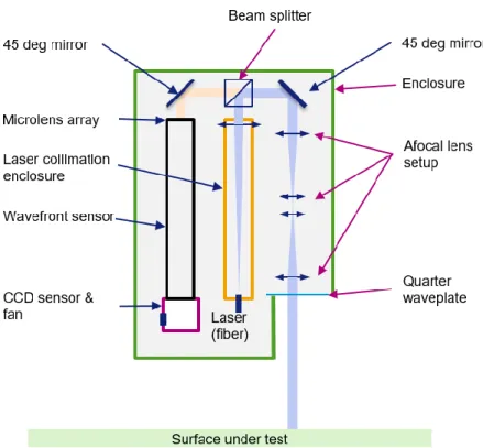
The SHARPeR optical head is shown in Figure 2.1, and is shown schematically in Figure 2.3. Illumination from a fibered laser (wavelength 405nm) is collimated, and after reflection by a polarizing beam splitter, passes through conditioning optics (45° mirror, afocal lens combination, quarter waveplate) before impinging on the test mirror. The beam reflected by the test mirror returns through the same afocal lens combination and other optical elements, after transmission through the beam splitter reaches the entrance pupil of the wavefront sensor (HASO UHP). The afocal lens setup projects a conjugate image of the wavefront at the mirror surface onto the entrance pupil of the HASO, at the microlens array. The wavefront sensor measures the direct wavefront slopes in tangential and sagittal directions. The laser beam is vertically polarized and the beam splitter reflects > 99% in vertical polarization and transmits > 99% in horizontal polarization. A quarter waveplate (QWP) is used to convert vertical to circular polarization in beam forward pass and from circular to horizontal polarization in return pass. The QWP plus polarized beam splitter combination also reduces the intensity from parasitic reflections entering the wavefront sensor.
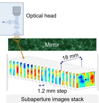
The optical head is mounted on the Q-Sys tangential translation and scans over the mirror length and acquires sub-aperture images with considerable overlap (>80%), with each image measuring the reflected wavefront distortion (of the test mirror) expressed as wavefront slopes. A stitching process is used to combine the overlapping sub-aperture slope maps into a long 2D map, similar to a panoramic picture. Finally, a 2D surface profile is reconstructed through integration of the tangential and sagittal slopes. In the as-delivered version of the system the subaperture slopes are stitched with StitchWave software provided by Imagine Optic.
ADAPA Bharath Reddy - January 2021 23
Figure 2.3 : Schematic of SHARPeR optical head. (The Afocal setup is simplified: the real instrument has more lenses with complex arrangement.)
2.1.3 Specifications of the SHARPeR at the European Synchrotron (ESRF)
SHARPeR consists of a highly accurate and precise optical head (SSHOH), stable and repeatable translation platform (STAMP) and a rotary, tip & tilt platform (RTT). The design and manufacture of the SSHOH was performed by Imagine Optic whilst that of the STAMP and RTT was produced by Q-Sys. The nominal specifications of SHARPeR installed at the ESRF are presented in Table 2.1, Table 2.2 and Table 2.3.24 ADAPA Bharath Reddy - January 2021
Table 2.1 : SHARPeR translations stage (STAMP) specifications
STAMP platform Sagittal axis (Y) Tangential axis (X) (carrying optical head)
Travel length 300 mm 1500 mm
Payload ≤ 200 kg ≤ 30 kg
Position accuracy ≤ 2 µm ≤ 2 µm
Repeatability ≤ 0.5 µm ≤ 0.5 µm
Maximum speed (on the fly measurements)
≤ 12.5 mm/s
Table 2.2 : SHARPeR rotation and tip-tilt (RTT) platform specifications
RTT platform Rotation axis Tip-Tilt axes
Range 190° ± 5°
Accuracy ≤ 15 µrad ≤ 30 µrad
Repeatability ≤ 5 µrad ≤ 5 µrad
Table 2.3 : SHARPeR optical head (SSHOH) specifications
Specifications
Aperture size 18.0 x 13.2 mm2
Number of microlenses 15 x 11
Tilt dynamic range ± 4 mrad
Sampling size ~1.2 mm
ADAPA Bharath Reddy - January 2021 25
Laser wavelength 405 nm
Weight < 10 kg
The optical head with specifications in Table 2.3 was designed for high slope sensitivity (<100 nrad) and to achieve that the wavefront sensor microlenses were chosen with ~300 mm focal length. Microlens size has to be compromised to achieve large tilt dynamic range. The total aperture size is limited by the CCD sensor size as well as the total cost of the system.
The wavefront sensor operates at nearly diffraction limited focal spot. Figure 2.4 shows a comparison of theoretical focal spot of a microlens in the CCD focal plane for a flat incidence wavefront to a measured CCD focal spot intensity. The spot is shown only in 1D, with the measured CCD intensities averaged along sagittal pixels. The theoretical profile is obtained from the square shaped microlens of the SHARPeR wavefront sensor (sinc2 shape), with calculated spot full width half maximum size (FWHM) of ~85 µm (or 15.5 pixels). The measured spot is very close to the theoretical diffraction limited focal spot.
Figure 2.4 : The measured microlens spot is compared to a theoretical sinc2 spot with FWHM of 15.5 pixels.