HAL Id: hal-00334161
https://hal.archives-ouvertes.fr/hal-00334161
Submitted on 24 Oct 2008
HAL is a multi-disciplinary open access
archive for the deposit and dissemination of
sci-entific research documents, whether they are
pub-lished or not. The documents may come from
teaching and research institutions in France or
abroad, or from public or private research centers.
L’archive ouverte pluridisciplinaire HAL, est
destinée au dépôt et à la diffusion de documents
scientifiques de niveau recherche, publiés ou non,
émanant des établissements d’enseignement et de
recherche français ou étrangers, des laboratoires
publics ou privés.
Sensorless Speed Control with Initial Rotor Position
Estimation for Interior Permanent Magnet Synchronous
Motor Drive
Mohamed Boussak
To cite this version:
Mohamed Boussak. Implementation and Experimental Investigation of Sensorless Speed Control with
Initial Rotor Position Estimation for Interior Permanent Magnet Synchronous Motor Drive. IEEE
Power Electronics, 2005, vol. 20 (n°6), pp. 1413-1422. �10.1109/TPEL.2005.854014�. �hal-00334161�
IEEE TRANSACTIONS ON POWER ELECTRONICS, VOL. 20, NO. 6, NOVEMBER 2005 1413
Implementation and Experimental Investigation
of Sensorless Speed Control With Initial Rotor
Position Estimation for Interior Permanent
Magnet Synchronous Motor Drive
Mohamed Boussak, Member, IEEE
Abstract—In this paper, a new approach to sensorless speed
con-trol and initial rotor position estimation for interior permanent magnet synchronous motor (IPMSM) drive is presented. In ro-tating condition, speed and rotor position estimation of IPMSM drive are obtained through an extended Kalman filter (EKF) algo-rithm simply by measurement of the stator line voltages and cur-rents. The main difficulty in developing an EKF for IPMSM is the complexity of the dynamic model expressed in the stationary co-ordinate system. This model is more complex than that of the sur-face PMSM, because of the asymmetry of the magnetic circuit. The starting procedure is a problem under sensorless drives, because no information is available before starting. The initial rotor posi-tion is estimated by a suitable sequence of voltage pulses intermit-tently applied to the stator windings at standstill and the measure-ment of the peak current values of the current leads to the rotor position. Magnetic saturation effect on the saliency is used to dis-tinguish the north magnetic pole from the south. To illustrate our work, we present experimental results for an IPMSM obtained on a floating point digital signal processor (DSP) TMS320C31/40 MHz based control system.
Index Terms—Extended Kalman filter (EKF), initial
posi-tion estimaposi-tion, interior permanent magnet synchronous motor (IPMSM), position and velocity estimation, sensorless drive.
NOMENCLATURE
- and -axis components of stator voltage on ro-tating frame.
- and -axis stator current on rotating frame. EMF constant.
Torque constant.
- and -axis stator self inductances. Leakage inductance.
Component of the self inductance due to space fun-damental air-gap flux.
Component of the self inductance due to rotor posi-tion dependent flux.
Armature winding resistance. Differential operator.
Manuscript received March 1, 2004; revised November 19, 2004. This work was supported by the Agence Nationale pour la Valorization de la Recherche (ANVAR). Recommended by Associate Editor M. A. Rahman.
The author is with the Ecole Généraliste d’Ingénieurs de Marseille (EGIM), Laboratoire de Génie des Systèmes Electriques (LGSE), Equipe Systèmes Mécatroniques (ESM), Technopôle de Château Gombert, Marseille Cedex 20 13451, France (e-mail: [email protected]).
Digital Object Identifier 10.1109/TPEL.2005.854014
Number of pole pairs.
Rotor speed at electrical angle. Rotor position at electrical angle. Rotor inertia.
Frictional constant. Electromagnetic torque. Load torque.
Control matrix. System state matrix.
Partial derivative system matrix. Output matrix.
Kalman filter gain matrix. State covariance matrix. System noise covariance matrix. Measurement noise covariance matrix. Weighting matrix of noise.
State vector. Output vector.
Disturbance input and output vectors.
Superscripts
Estimate quantities. Reference quantities. Transposed matrix. Sampling index.
Two-axis synchronous frame quantities. Two-axis stationary frame quantities.
I. INTRODUCTION
R
ECENTLY, the development and availability of very high energy permanent magnet materials has contributed to an increased use of the permanent magnet synchronous motor (PMSM) in high performance variable speed motors in many industrial applications. The inherent advantages of using a PMSM drive is that it has a high ratio of torque to weight, high power factor, faster response, rugged construction, easy maintenance, ease of control and high efficiency.The high performance speed or position control requires an accurate knowledge of rotor shaft position and velocity in order to synchronize the phase excitation pulses to the rotor position. This implies the need for speed or position sensors such as an absolute encoder or a magnetic resolver attached to the shaft of the motor. However, in most applications, these sensors present several disadvantages, such as reduced reliability, susceptibility
to noise, additional cost and weight and increased complexity of the drive system. The position and velocity sensorless control of PMSM drive overcome these difficulties.
In recent years, several solutions have been proposed in the literature for both speed and position sensorless methods for the IPMSM [1]–[34]. Three basic techniques are reported in the lit-erature for sensorless rotor position estimation of PMSM drive. • Techniques based on back-electromotive-force
(back-EMF) estimation [1]–[8].
• Techniques based on state observers [9], [10] and ex-tended Kalman filters (EKF) [11]–[16].
• Techniques based on spatial saliency tracking [17]–[34]. Position estimation based on back-EMF techniques estimate the flux and velocity from the voltage and current, which is es-pecially sensitive to the stator resistance at low speed range. The actual voltage information on the machine terminal can hardly be detected because of the small back-EMF of the machine and the system noise produced by the nonlinear characteristics of the switching devices. The back-EMF methods has good posi-tion estimaposi-tion in middle and high speed but it fails in the low speed region.
The magnitude of back-EMF voltage is proportional to the rotor speed, thus at standstill it is impossible to estimate the initial position. Therefore starting from unknown rotor position may be accompanied by a temporary reverse rotation or may cause a starting failure.
Because of its ability to perform state estimation for nonlinear systems that involve random noise environment, the EKF ap-pears to be a viable and computationally efficient candidate for the online estimation of speed and rotor position of an IPMSM [11]–[16].
The technique based on spatial saliency tracking using mag-netic saliency is suitable for zero speed operation and makes it possible to estimate the initial rotor position without parameter influences. For initial rotor position, there are mainly two basic methods based on using pulse signal injection [22]–[25] or si-nusoidal carrier signal injection [26]–[32].
In this paper, sensorless speed control with initial rotor posi-tion estimaposi-tion of an IPMSM is described. We propose a sen-sorless speed control of IPMSM using magnetic saliency tech-nique for initial position estimation and EKF for dynamic speed and position estimation. The IPMSM is characterized by the fact that its phase inductance varies appreciably in function of the rotor position and produces a spatial saliency useful for sensor-less speed control. For initial rotor position estimation, we use the technique based on magnetic saliency [22] by applying at a standstill, rectangular pulse voltage to the phase motor. There-fore, the initial rotor position at standstill can be estimated by measurement of the peak current values which depend on the rotor position. This method still has one problem in the estima-tion of magnetic pole posiestima-tion at standstill because there are two stable points.
It is important to distinguish the position from the north magnetic pole, because if the estimated initial rotor position is aligned with the south magnetic pole the couple becomes nega-tive and consequently the system will be unstable. Therefore, in
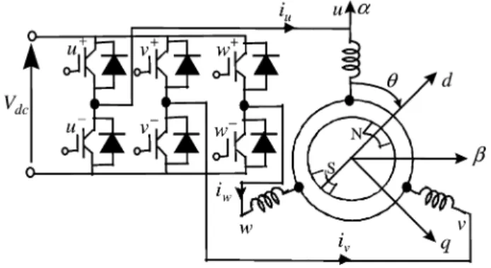
Fig. 1. Scheme of IPMSM drive system.
order to distinguish the north and south pole positions, we use magnetic saturation effects on the saliency to track the magnet pole polarity.
At low and high speed range, the sensorless control of an IPMSM drive is achieved by EKF algorithm. The measured quantities are the line currents for EKF state variables and the line voltages for EKF command vector. The voltages feeding the motor have pulse width modulation (PWM) waveforms. We propose to use the fundamental components of the voltages and currents. The current fundamental components are obtained by analog low pass filtering and the fundamental voltage compo-nents are obtained by sensing the digital switching of the in-verter through opto-couplers.
High-performance current regulator with the decoupling of the - and -axis and voltage command compensation is also proposed. The proposed sensorless speed control and initial rotor position estimation algorithms of IPMSM are imple-mented on a digital signal processor (DSP). The experimental results confirm the effectiveness of the proposed method.
II. IPMSM DRIVEEQUATIONS
A. IPMSM Equations
The control scheme of the proposed IPMSM drive system is shown in Fig. 1. The orthogonal two-phase frame is fixed to the stator windings. The frame shows the synchronously rotating reference frame and the d-axis coincides with the pole of the rotor, and, represents the angle of the rotor position.
The model for IPMSM is given as
(1)
where and .
The electromagnetic torque is given as
(2) The dynamic model of the IPMSM is developed on the basis of some simplifying hypotheses. Thus, saturation and iron losses are not considered. The back-EMF is assumed to have a sine form, while eddy currents are ignored.
BOUSSAK: IMPLEMENTATION AND EXPERIMENTAL INVESTIGATION OF SENSORLESS SPEED CONTROL 1415
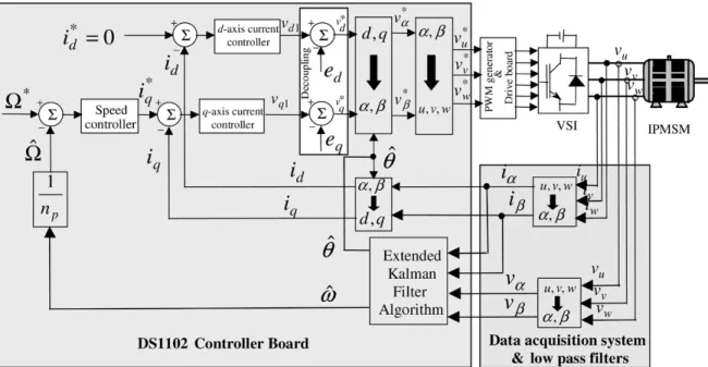
Fig. 2. Block diagram of the proposed sensorless speed control system.
The dynamic IPMSM nonlinear state equation is written in the following fourth order system
(3)
The - and -axis currents cannot be controlled independently by and voltages because of the cross-coupling effects be-tween two axes as shown in (1). For high performance speed control, - and -axis current regulators with the decoupling feed-forward compensation are proposed in this paper as shown in Fig. 2.
The -axis reference current is set to zero in order to max-imize the torque-to-current ratio of the IPMSM. The -axis ref-erence current is obtained from the speed error
through the speed regulator as shown in Fig. 2. The outputs of the current regulators gives the reference voltages in the rotating reference frame. In the block diagram of Fig. 2, the feed-forward terms, and , used for the decoupling con-trol are given by
(4) (5) The decoupling current control and the voltage command compensation are very useful in improving the performance of the current vector control and the flux weakening control.
B. EKF Algorithm
The EKF is one of the most widely used for tracking and es-timation for nonlinear systems due to its simplicity, optimality, trackability and robustness. In order to achieve sensorless con-trol of the salient-pole IPMSM, EKF is used for the estimation of the speed and rotor position. The line voltages of the motor and the load torque are the vector input variable of the system. The speed and the rotor position are the two magnitudes to be estimated, and with the motor current they constitute the state vector. The motor currents will be the only observable magni-tude that constitute the output vector.
For the implementation of an EKF for sensorless IPMSM drive, the choice of the two axis reference frame is essential. The ideal case is to use the rotating reference frame at-tached to the rotor. This solution is not compatible for IPMSM sensorless speed control because the input vector (currents and voltages) of the estimator are rotor position dependent. We can observe that an error of estimation in the initial position of the rotor can have serious repercussions by inducing error in the progress of the EKF with regard to the real system.
We seek to preserve the IPMSM control in the rotor reference frame. The speed and the position are estimated using only mea-surements of the stator voltages and currents. The EKF based observers use the motor model with quantities in the fixed refer-ence frame attached to the stator frame and are therefore independent of the rotor position.
The nonlinear dynamic state model of the IPMSM in a sta-tionary reference frame is described by the following expres-sions:
(6) The matrix elements of and are given in Appendix A. The two stator currents, the electrical speed and position are used as system state variables.
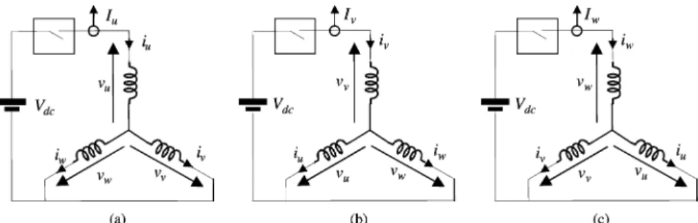
Fig. 3. Connections of IPMSM at standstill. (a) vector voltagev(100), (b) vector voltage v(010), and (c) vector voltage v(001).
The voltage components in the fixed stator-oriented frame are
(7) (8) The EKF algorithm should be calculated by using a micro-controller, and the dynamic state model given by (6) is to be expressed in a discrete state model.
The discrete state model is described by the following expres-sions:
(9) where is the state vector, is the output vector of the discrete state model defined as the measurement signals.
The output vector variables are defined as
(10) (11) The state vector variables are defined as
(12) (13) is given in (6).
The command vector is
(14)
(15)
The various symbols and the steps needed for the EKF com-putation are given in Appendix B.
III. INITIALROTORPOSITIONESTIMATIONMETHOD
At standstill, the motor currents and voltages are zero, the system of rotor position estimation using EKF algorithm gives no information for the initial position. Therefore, another tech-nique has to be found for rotor position estimation at standstill so as to achieve a stable start. The only information that one can use is based on the inductance of phase that is a function of the rotor position due to saliencies of the IPMSM.
In this paper, a method to estimate the initial rotor position at standstill of IPMSM motors is presented. This approach is based on the well-known method for estimating the initial rotor position by using the inductance variation due to the magnet position and an impressed stator current.
However, to estimate the initial rotor position, two kinds of a suitable sequence dc voltage rectangular pulses are applied from the inverter to the stator windings of the motor at standstill. One voltage pulse is applied with a short time duration , another with a long time duration .
At standstill, the gate signal control given to the switches and (Fig. 1) is provided to detect -phase current peak. In this case we represent the voltage vector where the connection is shown in Fig. 3(a). Similarly, the voltage vectors and are provided to detect -phase and -phase current peaks, respectively, and their connections are shown in Fig. 3(b) and (c).
The analysis of the current response leads to the initial rotor position estimation. The duration of the application of test signal is less than the average time constant so that the motor remains motionless. This is justified considering the inertia of the motor and the load system.
The inductance matrix is given as the equation shown at the bottom of the page.
We apply, respectively, the vector voltages , and to the motor at standstill with a short time duration in order not to saturate the machine. Although the motor
BOUSSAK: IMPLEMENTATION AND EXPERIMENTAL INVESTIGATION OF SENSORLESS SPEED CONTROL 1417
Fig. 4. Experimental current peaks response of phaseu; v, and w in the case of the nonsaturated condition.
Fig. 5. Experimental fluctuated component of current peaks response in the case of the nonsaturated condition.
is fed by a continuous current source, the phase current peaks and of the motor are sinusoidal functions of the rotor position given as
(16) (17) (18)
where is the dc current component
and is the amplitude of a fluctuated component. We mea-sure the phase current peaks and and we calculate the
difference , and .
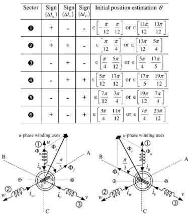
Fig. 4 shows the experimental phase current peaks , and for the angle of the rotor position in the case of the nonsaturated condition where the dc current component 0.95 A. Fig. 5 shows the measured difference of current peaks , and compared to the dc current component . The sector of initial electrical rotor position can be estimated by using the combination of signs of , and (Fig. 5), which is summarized in Table I, [22] with two domains.
An expression for the rotor position found in (19) was gen-erated by using trigonometric identities from the above expres-sions (16), (17), and (18) and isolating the angle terms for given as
(19) The position could be found by calculating the inverse tangent and dividing the remaining angle by two. For small angles, an
approximation of to the first order , we
TABLE I
ESTIMATE OFINITIALROTORPOSITION[22]
Fig. 6. Initial electrical rotor position estimation.
obtain the expression (20) of the estimated initial electrical rotor position according to the current fluctuations peak. Once the domain is specified, for example in the case where sign
, sign and sign , the initial electrical
rotor position can be estimated by the following expressions: (20) To distinguish north magnetic pole between and , we take into account the magnetic saturation by applying to the
motor pulse vector voltages , and during
the long time and we measure, respectively, the -phase, -phase and -phase current peaks. By comparing the current peaks obtained by using voltage pulse applied with short and long time, initial electrical rotor position can be discriminated between and . According to Fig. 6, when the permanent magnet flux has an inverse direction to that created by a cur-rent impulsion in the stator winding, this flux is subtractive and therefore the variation of the current is weaker than if the flux were additive.
Consequently when the north magnetic pole is in the vicinity of the axis of one of the three stator phases, the current response is necessarily higher in this phase. Under these conditions there
are thus three 120 sectors , and
, each one centered around the axis of the phase. When the north magnetic pole is in one of these three sectors, the current in the corresponding phase gives the highest current peak. For this type of test, the magnetic saturation appears at
Fig. 7. Experimental current peaks response of phaseu; v, and w in the case of the saturated condition.
TABLE II
DISCRIMINATION OFESTIMATEDINITIALROTORPOSITION
0, because the flux is added to the magnet flux and subtracted at (Fig. 6).
Fig. 7 shows the experimental phase current peaks and for the angle of the initial electrical rotor position in the case of the saturated condition where voltage pulse with a long time
is applied to the stator windings of the motor.
Let us take the previous example where sign ,
sign and sign , we have obtained two
estimate initial electrical rotor positions
or . In order to distinguish the initial
electrical rotor position estimation, we apply to the motor pulse vector voltages and we measure the current peaks and . We notice that if the current and
in this case the initial electrical rotor position is located in the
sector (see Fig. 7 and Table II) where ,
consequently the real initial electrical rotor position estimation is located in the sector (see Fig. 5 and Table I) where
. If it is not the case, then the real initial
posi-tion estimaposi-tion is located at . We can
apply the same reasoning for the other cases and the discrimi-nation between two estimated initial electrical rotor positions is summarized in Table II.
Fig. 8 shows the comparison between the actual and the es-timated initial electrical rotor position. The estimation was per-formed at 15 electrical degree intervals from 0 to 210 elec-trical degrees. The comparison shows a good agreement and confirms the effectiveness of the proposed method.
Fig. 9 shows the experimental of initial electrical rotor posi-tion estimaposi-tion error over the range from 0 to 210 electrical degrees. As a results, the average and maximum values of the error for the initial rotor position estimation are 1.14 and 7.4
Fig. 8. Experimental of initial electrical rotor position estimation.
Fig. 9. Experimental of initial electrical rotor position estimation error.
electrical degrees, respectively. The obtained values for initial electrical rotor position are small for the purposes of the appli-cation. The accuracy of initial rotor position estimation is de-pendent on the accuracy of current peaks measurement.
The initial rotor position estimation is achieved by means of the response current of two types of voltage pulse applied to the IPMSM, one during short time , the other during long time . The system of control makes it possible to apply and to manage the response of the signals tests to the machine with the inverter which operates in this case like a chopper. Thus, the magnitude of the voltage pulse is equal to the dc-bus voltage of the input inverter ( 316 V).
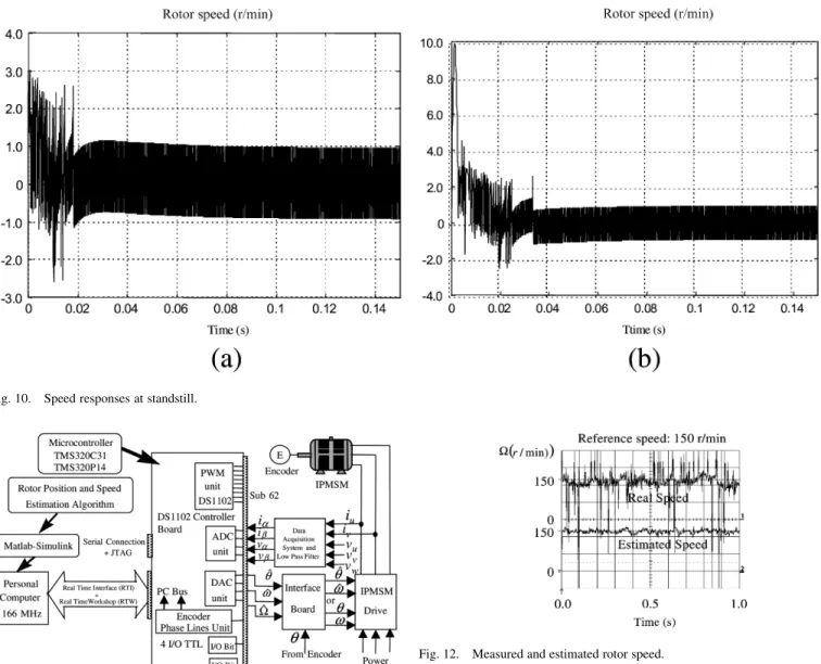
When the voltage pulse with short or long time is applied to the stator windings of the motor, we noted that the machine rotor is practically at standstill with a small vibration (Fig. 10). The current generated by the high frequency voltage pulse applied to the motor produces an impulse low magnitude torque with null average value.
Fig. 10 shows the speed responses at standstill when the voltage pulse with short time [Fig. 10(a)] and with long time [Fig. 10(b)] is applied to the stator windings of the motor with initial rotor position electrical degrees. It can be seen the machine rotor did not move, but it is in a critical position of unstable balance and we note the occurrence of a small vibration on the rotor. The speed is within 1 r/min to 1 r/min and its average value is null, thus the motor keep at standstill.
BOUSSAK: IMPLEMENTATION AND EXPERIMENTAL INVESTIGATION OF SENSORLESS SPEED CONTROL 1419
Fig. 10. Speed responses at standstill.
Fig. 11. Experimental set-up for sensorless speed control system.
IV. SENSORLESSDRIVEIMPLEMENTATION
The DSP System used for sensorless IPMSM drive control implementation is based on the DS1102 controller board from dSpace GmbH. The heart of the DS1102 controller board is a TMS320C31 32-b DSP floating-point processor.
Fig. 11 shows the complete DSP system setup used for sen-sorless speed control of the IPMSM drive implementation. The proposed sensorless controller scheme is based on a current-controlled voltage source inverter (VSI) structure. For the cur-rent control loops, we use the synchronously rotating refer-ence frame attached to the rotor. The EKF used for the dynamic rotor position and speed estimation operates in the sta-tionary reference frame.
All the system controls of the IPMSM drive are implemented inside the DS1102 controller board. A resolver is used for real speed measurement to be compared to the estimated speed. The PWM logic is generated by an external analog circuit. The line current is detected by Hall LEM LA 25-NP and is converted through a 12 b A/D converter. In A PWM drive, the line-to-line voltage changes very rapidly. The fundamental components of
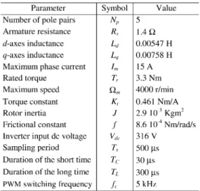
Fig. 12. Measured and estimated rotor speed.
the line-to-line voltages are reconstructed by sensing the digital switching information of the inverter through opto-couplers. To retrieve the fundamental components from the digital switching information of the inverter, we use a direct analog method.
The voltage components and in the stator axis frame are obtained through coordinate transformation of the phase , and using operational amplifier circuit with a min-imum offset. The voltages are then passed through analog low pass filters to eliminate the high frequency harmonics and are converted through a 16 b A/D converter.
In our experimental test we assume that the dc-bus voltage is constant. If the dc-bus voltage varies it affects the voltage mea-surement accuracy, therefore the meamea-surement of dc-bus voltage is necessary. The carrier frequency of a conventional sinusoidal PWM inverter is 5 kHz, in which three-phase sinusoidal refer-ence voltages are compared with a triangular wave. The EKF algorithm predicts the state in with the sampling period fixed at 500 s.
The IPMSM has highly nonsymmetrical distribution of re-actances in rotor frame. All the experimental results are obtained using as feedback estimated rotor speed and position. The measurements of the actual rotor speed and position are de-tected with a resolver. The choice of initial values for matrixes
Fig. 13. Estimated rotor speed error.
Fig. 14. Measured and estimated rotor position.
and is very important. To obtain the coefficients of the covariance matrix, a Gaussian noise generator is used and con-sequently the initial values used for each matrix are given as
where is the identity matrix of dimension (4 4).
In Fig. 12 the measured and estimated rotor speed is reported in steady state with a speed command of 150 r/min. It can be seen therefore that the estimated speed shows a good corre-spondence to the actual rotor speed with an error of a less than
9 r/min shown in Fig. 13.
In Fig. 14, the measured and estimated rotor position is reported in steady state with a speed reference of 150 r/min. According to the experimental results, the estimated position shows good correspondence to the actual rotor position with an average error of a less than electrical angle degrees (Fig. 15) which corresponds to about 1.1 mechanical angle degrees.
The parameter of the PMSM used for simulation and experi-ment is given in Table III.
V. CONCLUSION
In this paper, a new approach initial rotor position estima-tion including magnet polarity and sensorless speed control of IPMSM has been proposed. The feasibility of initial rotor po-sition estimation and sensorless speed control of IPMSM drive has been investigated through experiments as well as computer simulations. The estimation of the initial rotor position is based on the investigation of the magnetic saliency without requiring
Fig. 15. Estimated rotor position error.
TABLE III
DATA OFPMSM USED INSIMULATION ANDEXPERIMENT
knowledge the motor parameters except the ration of -axis and -axis inductance. The magnet polarity is identified using the magnetic saturation effect. According to the experimental re-sults, the average of the estimation initial rotor position error is 1.14 electrical degrees, and the maximum estimation error is 7.4 electrical degrees.
In rotating condition, speed and rotor position estimation of IPMSM drive are obtained through an extended Kalman filter (EKF) algorithm. The correspondence of the estimated rotor po-sition to the actual popo-sition indicates that the EKF algorithm is effective and can be used to replace the position encoder. The coupling of initial rotor position estimation technique to EKF algorithm for sensorless control algorithm make possible to operate the motor from zero speed up to full speed. The esti-mated algorithm was implemented in a digital controller using a DSP, and an experimental speed control system consisting of an IPMSM and a voltage-source PWM inverter was made up and tested.
The experimental results show that the proposed method has good sensorless speed control performance with initial rotor po-sition estimation. As a result, good controllability over the wide speed range was confirmed, which proved the feasibility of the proposed method.
BOUSSAK: IMPLEMENTATION AND EXPERIMENTAL INVESTIGATION OF SENSORLESS SPEED CONTROL 1421
APPENDIX A The matrix elements of and in (6) are
(A1) (A2) (A3) (A4) (A5) (A6) (A7) (A8) (A9) (A10) (A11) (A12) (A13) (A14) with . APPENDIX B
The EKF is a mathematical tool for estimating the states of dynamic nonlinear systems. The nonlinear state space equations of the motor model are written in the following continuous form:
(B1) Where the initial state vector is modeled as a Gaussian-random vector with mean and covariance
is the deterministic control input vector, is zero-mean Gaussian noise matrix of state model which is independent
of with a covariance matrix is a zero-mean
white Gaussian noise matrix of output model with a covariance matrix is the weighting matrix of noise, the output vector and the control matrix.
The filter has a predictor-corrector structure as follows (su-perscripts and refer to the time before and after the measurements have been processed). The discrete form of EKF algorithm can be summarized as follows.
1) Prediction of states
(B2)
2) Prediction of the covariance matrix of states
(B3) where
(B4)
(B5) (B6) 3) Kalman gain matrix
(B7) where
(B8) 4) Update the covariance matrix of states
(B9) 5) Update of the state estimation
(B10)
REFERENCES
[1] S. Ogasawara and H. Akagi, “An approach to position sensorless drive for brushless dc motor,” IEEE Trans. Ind. Appl., vol. 27, no. 5, pp. 928–933, Sep./Oct. 1991.
[2] A. B. Kulkarni and M. Ehsani, “A novel position sensor elimination technique for the interior permanent-magnet synchronous motor drive,”
IEEE Trans. Ind. Appl., vol. 28, no. 1, pp. 144–150, Jan./Feb. 1992.
[3] J. S. Kim and S. K. Sul, “New approach for the low speed operation of PMSM drives without rotational position sensors,” IEEE Trans. Ind.
Electron., vol. 11, no. 3, pp. 512–519, May 1996.
[4] Z. Chen, M. Tomita, S. Doki, and S. Okuma, “An extended electromo-tive force model for sensorless control of interior permanent magnet synchronous motors,” IEEE Trans. Ind. Electron., vol. 50, no. 2, pp. 288–295, Apr. 2003.
[5] S. Morimoto, K. Kawamato, M. Sanada, and Y. Takeda, “Sensorless con-trol strategy for salient pole PMSM based on extended EMF in rotating reference frame,” IEEE Trans. Ind. Appl., vol. 38, no. 4, pp. 1054–1061, Jul./Aug. 2002.
[6] S. Östlund and M. Brokemper, “Sensorless rotor position detection from zero to rated speed for an integrated PM synchronous motor drive,” IEEE
Trans. Ind. Appl., vol. 32, no. 5, pp. 1158–1165, Sep./Oct. 1996.
[7] H. Kim, M. C. Harke, and R. D. Lorenz, “Sensorless control of interior permanent-magnet machine drives with zero phase lag position estima-tion,” IEEE Trans. Ind. Appl., vol. 39, no. 6, pp. 1726–1733, Nov./Dec. 2003.
[8] B. N. Mobarakeh, F. M. Tabar, and F. M. Sargos, “Mechanical sensor-less control of PMSM with online estimation of stator resistance,” IEEE
Trans. Ind. Appl., vol. 40, no. 2, pp. 457–471, Mar./Apr. 2004.
[9] R. B. Sepe and J. H. Lang, “Real time observer-based adaptive control of a permanent magnet synchronous motor without mechanical sensors,”
[10] J. A. Solsona and M. I. Valla, “Disturbance and nonlinear Luenberger observers for estimating mechanical variables in permanent magnet synchronous motors under mechanical parameters uncertainties,” IEEE
Trans. Ind. Electron., vol. 50, no. 4, pp. 717–725, Aug. 2003.
[11] S. Bolognani, R. Oboe, and M. Zigliotto, “Sensorless full-digital PMSM drive with EKF estimation of speed and rotor position,” IEEE Trans. Ind.
Electron., vol. 46, no. 1, pp. 184–191, Feb. 1999.
[12] R. Dhaouadi, “Application of Stockhastic Filtering to a Permanent Magnet Synchronous Motor Drive System Without Electromechanical Sensors,” Ph.D. Thesis, University of Minnesota, Oct. 1990.
[13] H. W. Kim and S. K. Sul, “A new motor speed estimation using Kalman filter in low-speed range,” IEEE Trans. Ind. Electron., vol. 43, no. 4, pp. 498–504, Aug. 1996.
[14] G. Henneberger, B. J. Brunsbach, and T. Klepsch, “Field-oriented con-trol of synchronous and asynchronous drives without mechanical sen-sors using a Kalman filter,” in Proc. EPE’91, vol. 3, 1991, pp. 664–671. [15] Y. H. Kim and Y. S. Kook, “High performance IPMSM drives without ro-tational position sensors using reduced-order EKF,” IEEE Trans. Energ.
Conv., vol. 14, no. 4, pp. 868–873, Dec. 1999.
[16] M. Boussak, “Digital signal processor based sensorless speed control of a permanent magnet synchronous motor drive using extended Kalman filter,” EPE J., vol. 11, no. 3, pp. 7–15, Aug. 2001.
[17] M. Schroedl, “Control of a permanent magnet synchronous machine using a new position estimator,” in Proc. ICEM’90, Boston, MA, 1988, pp. 1218–1224.
[18] S. Ogasawara and H. Akagi, “Implementation and position control per-formance of a position sensorless IPM motor drive system based on magnetic saliency,” IEEE Trans. Ind. Appl., vol. 34, no. 4, pp. 806–812, Jul./Aug. 1998.
[19] P. L. Jansen and R. B. Lorenz, “Transducerless position and velocity es-timation in induction and salient AC machines,” IEEE Trans. Ind. Appl., vol. 30, no. 2, pp. 240–247, Mar./Apr. 1995.
[20] J. H. Jang, S. K. Sul, J. I. Ha, K. Ide, and M. Sawamura, “Sensorless drive of surface mounted permanent magnet motor by high frequency signal injection based on magnetic saliency,” IEEE Trans. Ind. Appl., vol. 9, no. 4, pp. 1031–1039, Jul./Aug. 2003.
[21] M. W. Degner and R. D. Lorenz, “Using multiple saliencies for the es-timation of flux, position, and velocity in AC machines,” IEEE Trans.
Ind. Appl., vol. 34, no. 5, pp. 1097–1104, Sep./Oct. 1998.
[22] N. Matsui, “Sensorless PM brushless dc motor drives,” IEEE Trans. Ind.
Electron., vol. 43, no. 2, pp. 300–308, Apr. 1996.
[23] S. Nakashima, Y. Inagaki, and I. Miki, “Sensorless initial rotor posi-tion estimaposi-tion of surface permanent magnet synchronous motor,” IEEE
Trans. Ind. Appl., vol. 36, no. 6, pp. 1598–1603, Nov./Dec. 2000.
[24] M. Tursini, R. Petrella, and F. Parasiliti, “Initial rotor position estima-tion method for PM motors,” IEEE Trans. Ind. Appl., vol. 39, no. 6, pp. 1630–1640, Nov./Dec. 2003.
[25] H. Kim, K. K. Huh, R. D. Lorenz, and T. M. Jahns, “A novel method for initial rotor position estimation for IPM synchronous machine drives,”
IEEE Trans. Ind. Appl., vol. 40, no. 5, pp. 1369–1378, Sep./Oct 2004.
[26] A. Consoli, G. Scarcella, and A. Testa, “Industry application of zero-speed sensorless control techniques for PM synchronous motors,” IEEE
Trans. Ind. Appl., vol. 37, no. 2, pp. 513–519, Mar./Apr. 2001.
[27] M. J. Corley and R. D. Lorenz, “Rotor position and velocity estimation for a salient-pole permanent magnet synchronous machine at standstill and high speeds,” IEEE Trans. Ind. Appl., vol. 34, no. 4, pp. 784–789, Jul./Aug. 1998.
[28] T. Noguchi, K. Yamada, S. Kondo, and I. Takahashi, “Initial rotor posi-tion estimaposi-tion of sensorless PM motor with no sensitivity to armature resistance,” IEEE Trans. Ind. Electron., vol. 45, no. 1, pp. 118–125, Feb. 1998.
[29] J. I. Ha, K. Ide, T. Sawa, and S. K. Sul, “Sensorless rotor position esti-mation of an interior permanent magnet motor from initial states,” IEEE
Trans. Ind. Appl., vol. 39, no. 3, pp. 761–767, May/Jun. 2003.
[30] T. Noguchi and S. Kohno, “Mechanical sensorless permanent magnet motor drive using relative phase information of harmonic currents caused by frequency modulated three phase PWM carries,” IEEE Trans.
Ind. Appl., vol. 39, no. 4, pp. 1085–1092, Jul./Aug. 2003.
[31] M. E. Haque, L. Zhong, and M. F. Rahman, “A sensorless initial rotor position estimation scheme for direct torque controlled interior perma-nent magnet synchronous motor drive,” IEEE Trans. Power Electron., vol. 18, no. 6, pp. 1376–1383, Nov. 2003.
[32] T. Aihara, A. Toba, T. Yanase, A. Mashimo, and K. Endo, “Sensorless torque control of salient-pole synchronous motor at zero-speed opera-tion,” IEEE Trans. Power Electron., vol. 14, no. 1, pp. 202–208, Jan. 1999.
[33] M. Boussak, “Sensorless speed control and initial rotor position esti-mation of an interior permanent magnet synchronous motor drives,” in
Proc. IEEE IECON’02, vol. 1, 2002, pp. 662–667.
[34] , Synthèse de commandes vectorielles des actionneurs asynchrones
et synchrones avec et sans capteur mécanique. Marseille, France: Ha-bilitation à Diriger des Recherches (HDR), Univ. d’Aix Marseille III, Mar. 30, 2004.
Mohamed Boussak (S’89–M’89) was born in
El Haouaria, Tunisia, on December 28, 1958. He received the B.S. and D.E.A. degrees from the Ecole Normale Supérieure de l’Enseignement Technique de Tunis (ENSET), Tunis, Tunisia, in 1983 and 1985, respectively, the Ph.D. degree from Pierre et Marie Curie University, Paris, France, in 1989, and the “Habilitation à Diriger des Recherches” (HDR) degree from Aix-Marseille III University, Marseille, France, in 2004, all in electrical engineering.
From 1989 to 1990, he was a Researcher with the Ecole Supérieure d’Ingénieurs de Marseille (ESIM). From 1990 to 1991, he was a Research Teacher in electrical engineering with the Claude Bernard of Lyon 1 University, Lyon, France. From 1991 to 2004, he was an Associate Professor with the Ecole Supérieure d’Ingénieurs de Marseille (ESIM). Since July 2004, he has been an Associate Professor of electrical machines and drives with the Ecole Généraliste d’Ingénieurs de Marseille (EGIM). He is a member of Lab-oratory of Electrical Engineering Systems (LGSE), Marseille, France. He has authored more than 60 papers in international conferences and technical jour-nals in the area as well as many patents. His research is in the areas of electrical machines, power conversion systems, sensorless vector control ac motor drives, advanced digital motion control and diagnostics.
Dr. Boussak is Member of IEEE Industry Application, IEEE Industrial Elec-tronics, and IEEE Power Electronics Societies. He serves as a member of the Technical Program Committees of several international conferences and tech-nical journals in the power electronics and motor drives fields.