HAL Id: hal-01424239
https://hal.archives-ouvertes.fr/hal-01424239
Submitted on 14 Mar 2017
HAL is a multi-disciplinary open access
archive for the deposit and dissemination of
sci-entific research documents, whether they are
pub-lished or not. The documents may come from
teaching and research institutions in France or
abroad, or from public or private research centers.
L’archive ouverte pluridisciplinaire HAL, est
destinée au dépôt et à la diffusion de documents
scientifiques de niveau recherche, publiés ou non,
émanant des établissements d’enseignement et de
recherche français ou étrangers, des laboratoires
publics ou privés.
ORION: Orientation Estimation Using Commodity
Wi-Fi
Mohamed Naoufal Mahfoudi, Thierry Turletti, Thierry Parmentelat, Fabien
Ferrero, Leonardo Lizzi, Robert Staraj, Walid Dabbous
To cite this version:
Mohamed Naoufal Mahfoudi, Thierry Turletti, Thierry Parmentelat, Fabien Ferrero, Leonardo Lizzi,
et al.. ORION: Orientation Estimation Using Commodity Wi-Fi. Workshop on Advances in Network
Localization and Navigation (ANLN), May 2017, Paris, France. pp.1033-1038. �hal-01424239�
ORION: Orientation Estimation Using
Commodity Wi-Fi
M.N. Mahfoudi
∗, T. Turletti
∗, T. Parmentelat
∗, F. Ferrero
†, L. Lizzi
†, R. Staraj
†and W. Dabbous
∗∗ Universit´e Cˆote d’Azur, Inria Sophia Antipolis, France † Universit´e Cˆote d’Azur, LEAT - CNRS UMR 7248, France
Contact author: [email protected]
Abstract—With MIMO, Wi-Fi led the way to the adoption of antenna array signal processing techniques for fine-grained local-ization using commodity hardware. These techniques, previously exclusive to specific domains of applications, will spur interest to reach beyond localization, and now allow to consider estimating the device’s orientation in space, that once required other sources of information. Wi-Fi’s popularity and the availability of metrics related to channel propagation (CSI), makes it a candidate readily available for experimentation. Accordingly, we propose the ORION system to estimate the orientation (heading and yaw) of a MIMO Wi-Fi equipped object, relying on a joint estimation of the angle of arrival and the angle of departure. Although the CSI’s phase data is plagued by several phase inconsistencies, we demonstrate that an appropriate phase compensation strategy significantly improves estimation accuracy. Our technique allows estimating orientations within millimeter-level precision.
Keywords—Localization, Orientation estimation, Wi-Fi, Chan-nel State Information (CSI).
I. INTRODUCTION
With the popularity of Wi-Fi, it is thought that indoor localization would be better integrated in the existing in-frastructure and would thus avoid the deployment of a new dedicated system. This idea was further reinforced by the shift to MIMO techniques through the adoption of the 802.11n standard. Fingerprinting [1] and other power-based ranging techniques [2] cleared the way for more sophisticated localiza-tion approaches based on radar tracking techniques [3]. Hence, MIMO naturally extended the set of localization techniques a SISO Wi-Fi infrastructure can propose. The infrastructure is now capable of locating a terminal with decimeter level precision, either by using time-of-flight based ranging [4], [5], or angle of arrival (AoA) estimation techniques [6], [7]. With MIMO-OFDM Wi-Fi chipsets, we are set to unlock more potential than simply localization, knowing that radar tracking techniques allow the estimation for instance of the orientation of a given target [8], [9]. Inertial measurement units (IMUs) were used for robust estimation of a terminal’s position based on Wi-Fi signals by identifying the physical orientation and compensating the localization estimation error [10], [11], [12]. Although IMUs, which consist of a combination of accelerometers, gyroscopes and lately also magnetometers, provide orientation information for devices, the gyroscope will only provide the derivative of the yaw and magnetometers tend to suffer from perturbation in measuring the heading in indoor environments [13]. Finally, Wi-Fi signals were used to estimate the position and orientation of devices by building a radio map using RSS. However, this estimation was limited to 4 possible orientations only [14], [15]. An important question
to answer is therefore: can we propose an accurate alternative to fingerprinting and IMU-based orientation estimation, using radar tracking techniques on commodity Wi-Fi infrastructure? In this paper, we allow off-the-shelf MIMO Wi-Fi access points to estimate the orientation of a MIMO-enabled terminal using antenna array signal processing, by jointly estimating both the AoA and the angle of departure (AoD). The idea is to propose a deployable system in every Wi-Fi platform without modifying the equipment. The benefit would range from providing a reference for IMU calibration, to indoor clients orientation tracking, as they will all have the same heading reference unlike magnetometers measurements, and enabling simultaneous localization and mapping (SLAM) [16] techniques, which require position and orientation measure-ments.
Designing such a system in commodity Wi-Fi equipments implies tackling several design challenges:
1) Channel state information (CSI), i.e., the output matrix used for antenna array signal processing, suffers from phase shifts. These errors should be compensated in order to achieve higher accuracy, as well as reproducibility of AoA estimation results.
2) Estimating a signal’s AoD relies on the measurement of the phase difference between transmitted synchronized signals. The targeted system should provide an approach for estimating the AoD by both allowing a synchronized transmission on multiple RF chains, and being robust to phase inconsistencies associated to the chosen transmis-sion scheme.
3) Tracking orientation requires a series of AoAs and AoDs estimations. These measurements usually suffer from sta-tistical noise and could translate in a jerky observation of actual monitored orientation. The system should be robust to such estimation uncertainty.
Thus, our system design pays special attention to detecting and correcting phase inconsistencies, and to reducing measure-ment noise. Hence, our contributions are along the same lines: i) we propose a signal processing phase correction technique for calibrating the system based on a single initial measurement reference, so as to provide meaningful, accurate and repro-ducible estimation of the angle of arrival; ii) we present a novel mechanism for estimating the angle of departure of the signal by a Wi-Fi access point, using a common MIMO technique called spatial multiplexing (SM); using SM introduces some phase inconsistencies that we correct before launching the estimation; to the best of our knowledge ORION is the first to
propose angle of departure estimation on commodity Wi-Fi; and iii) we propose an approach for tracking the orientation of the terminal; for that matter, we apply a joint estimation of AoA and AoD so as to enhance estimation accuracy. Then, we employ noise reduction and outlier detection techniques to smooth our estimations. ORION essentially relies on signal processing done in a remote server to avoid hardware modifi-cations of the access points. This facilitates seamless adoption. The paper is organized as follows. Section II presents the adopted system model for the joint AoA and AoD estimation. Then in Section III, we present different techniques necessary for accurate and reproducible AoA and AoD estimations Sec-tion IV focuses on tracking terminal orientaSec-tion. In SecSec-tion V, we give a brief presentation of the implementation and assess our system performance in two distinct environments, an office room and the R2lab anechoic chamber [17]. Finally, we lay down the conclusion in Section VI.
II. THE SYSTEM MODEL
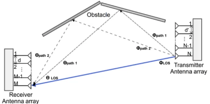
In a MIMO system with N -element send and M -element receive coplanar uniform linear arrays (ULA) with omnidi-rectional antennas as the one depicted in Fig. 1, a joint estimation of azimuth AoA and azimuth AoD is possible. At the transmitter side, N signals are emitted with identical bandwidth and center frequency. The steering vector of an M -antenna array representing the relative phases at each -antenna of a signal received at direction θ, can be written as follows: a(θ) = [1 a2(θ) · · · al(θ) · · · aM(θ)]T (1)
with al(θ) = e−j
2π
λ(l−1)d sin(θ), where l is the antenna index, λ
the wavelength and d the half-wavelength inter-antenna spac-ing. In a multipath environment, the i-th path is represented by θiand φi, which are respectively the AoA and AoD of this
path. Hence, the received signal vector is in the form: x = [ar(θ0) ⊗ at(φ0), ar(θ1) ⊗ at(φ1), · · · ,
ar(θp−1) ⊗ at(φp−1)] · s + n (2)
where x is the M N × 1 received signal vector, at(φ) is
the transmit steering vector, ar(θ) is the receive steering
vector, s = [s1 s2 · · · sp]T is the vector representing the
complex gain of the p paths with si = αiejωi, αi being
the reflection coefficient of the i-th path and ejωi its phase
component mainly due to Doppler effect. As the Doppler shift has almost no effect on the orthogonality of the signals, we chose to ignore it in the remaining of the article. n is assumed to be a white noise Gaussian vector with zero mean. Here, ⊗ represents the Kronecker product and (.)T denotes the vector/matrix transpose. Lowercase, bold uppercase and bold lowercase denote respectively scalars, vectors and matrices.
In order to estimate the AoA and AoD, we adopted a subspace method that consists in computing the covariance matrix of the received signal x, Rxx = E[xxH]. As the
covariance matrix Rxx is not perfectly known, we need to
estimate it. The classical approach would be to take k CSI matrices from k consecutive frames and compute the sample covariance matrix. Taking into account time delay constraints, we choose instead to use frequency domain samples for our estimation.
Fig. 1: Coplanar N -element ULA sender and M -element ULA receiver.
In order to estimate the channel between each receiving chain and the spatial stream transmitter, the 802.11n amend-ment adopted the high-throughput long training field (HT-LTF). The transmitter sends an 802.11n “greenfield” packet with the HT-LTF training symbols known by the transmitter and receiver for each one of the subcarriers. HT-LTF symbols are encoded over time and space with spatial streams orthog-onal between each other. As the sequence is known at the reception, the CSI matrix is estimated for instance by a least square method. Therefore, we can make use of CSI values of each subcarrier as estimation samples.
After applying the phase correction proposed in Section III, we compute the sample covariance matrix from the CSI values corresponding to L subcarriers bRxx = L1
PL
i=1xx
H. Then,
we compute the eigenvectors and eigenvalues of the Rxx by
an eigen-decomposition, where Rxx = QDQH. Based on the
assumption that the signal and noise vectors are uncorrelated, we partition the Q matrix containing the eigenvectors into two subspaces, one spanned by the signal eigenvectors Qs
corre-sponding to the largest eigenvalues and the other by the noise eigenvectors Qn. This is done using the Akaike information
criterion (AIC). Then we use the MUSIC algorithm [18], to estimate the parameters by launching a search over all the possible values of steering vectors to identify the ones related to the signal. This is possible because, as mentioned earlier, the signal and noise are uncorrelated and thus the signal steering vectors are orthogonal to the noise eigenvectors and ultimately the noise subspace. In practice, we compute what we call the pseudospectrum from the quadratic function,
P(θi, φi) =
1
(ar(θi) ⊗ at(φi))H Qn QHn(ar(θi) ⊗ at(φi))
where (.)H denotes the Hermitian operation. The estimated AoA and AoD correspond therefore to peaks in the computed spectrum.
III. AOAANDAODESTIMATION
Let us first focus on phase corrections required for AoA estimation. As described above, modern Wi-Fi NICs provide a CSI matrix for each sub-carrier. The CSI’s phase and amplitude information capture the channel conditions (reflection, fading, path loss, scattering) necessary for computing the angle of arrival. The channel gain matrix Y corresponding to one
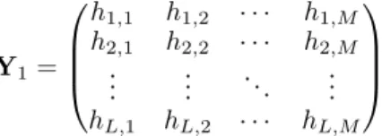
transmitted stream is therefore in the form: Y1= h1,1 h1,2 · · · h1,M h2,1 h2,2 · · · h2,M .. . ... . .. ... hL,1 hL,2 · · · hL,M (3)
This matrix representation with a numbering subscript (Yi=1,2) will showcase the adopted phase corrections for the
AoA estimation. Here, L is the number of subcarriers or frequencies, M is the number of receiving antennas, and hL,M
is the channel complex gain for the Lth subcarrier and the M -th antenna.
However, exploiting phase information provided by com-mercial off-the-shelf (COTS) wireless cards is rather challeng-ing. In fact, some of wireless cards design choices are at the origin of several distortions in the phase information. RF oscillator offset, carrier frequency offset (CFO) and sampling frequency offset (SFO) are among the most prominent ones.
RF oscillator phase offset occurs when, upon starting up a wireless card, RF chains are locked at different instants. Therefore, each RF chain will have a different constant value ψ added to the measured phase. These phase values are constant for a given wireless card till the next recalibration or reset, and thus we only need to correct the phase offset once for each session. Correcting the phase at the hardware level is neither practical nor feasible, so we alternatively opt for software preprocessing. As the phase offset is constant during the entire session, tuning on a reference signal arriving at a known direction θref helps in compensating the undesired
hardware-induced phase shift ψ. This implies applying a phase rotation on the measured target signal phase taking into account the reference signal phase. Thus, the new CSI matrix will be:
Y2= h1,1 h1,2∆2 · · · h1,M∆M h2,1 h2,2∆2 · · · h2,M∆M .. . ... . .. ... hL,1 hL,2∆2 · · · hL,M∆M (4)
where ∆j = ψ1· ψj is the relative phase between the first and
j-th RF chain for the reference signal coming at θref. Here
(.) denotes the conjugate.
Carrier frequency offset (CFO) occurs when the transmit-ting oscillator and the receiver are not synchronized: when the baseband downconversion is done, the signal phase will be rotated by a constant value function to the frequency offset. However, as the CFO is applied equally over all the RF chains, it does not affect the angle of arrival estimation.
Sampling frequency offset (SFO) is due to the fact that the sender and the receiver sample the signal at different times. The offset δt is the same for all the subcarriers and all RF chains. In Wi-Fi OFDM, the subcarriers have equally spaced frequencies with ∆f = 312.5 kHz. However, the phase rotation is not the same for all the subcarriers and is equal to e−j2πk∆f δtfor the k-th subcarrier. The peculiar feature of this phase offset is that it varies linearly across subcarriers in all RF chains. This linearity is not visible at first since the phase wraps around every 2π. Therefore, phase unwrapping is the only way to observe phase trends across subcarriers and particularly the aforementioned linearity. This phase shift does not affect our
Fig. 2: Signal radiation from an N -element uniform linear antenna array: The k-th antenna transmits a signal with a phase shift of e−j2π(k−1)d0sin(φ)fc
relatively to the reference antenna.
Fig. 3: Partial view of the MIMO Transmission Block as described and specified in the IEEE 802.11n standard.
estimation, as we only focus on phase shifts sanitation between different RF chains while estimating the angle of arrival. Thus, an SFO phase correction that allows consistent inter-subcarrier phase shift information is not needed.
Now let us focus on AoD estimation. The angle of depar-ture (AoD) is the angle between the transmit array normal and a given target. We are interested in estimating the orientation of the receiver in a line-of-sight (LoS) scenario. Therefore, the receiver plays the role of the target in our study. The idea behind AoD measurement is to send a signal from each element of an antenna array and measure the relative phase between the signals at the receiver antenna, see Fig. 2.
The varying nature of the wireless medium imposes that measurements are performed in respect to a certain time delay constraint. In fact, in order to collect accurate measurements, we need to make sure that the frame transmission time is lower than the channel coherence time, in order to avoid phase changes due to channel variation. Otherwise, the phase shift measured between the streams wouldn’t be consistent with the phase shift relative to the angle of departure. In the case of measurements on the 5.32 GHz band using 802.11 OFDM with an environment speed (walking speed) of 0.33m/s, we typically have 5.85 Hz of Doppler frequency according to Clarke’s model, which is equivalent to a coherence time of Tc= 72.3 ms [19] and which is much bigger than the time
symbol of Ts= 3.2 µs and the transmission time of 10ms.
The angle of departure estimation is based on the mea-surement of the phase difference between signals coming to one antenna from the same origin. The idea is to transmit temporally-delayed signals on different antennas and estimate the phase shift between the received signals. This measurement is difficult to perform when no fine grain synchronization between the signals is available. This criteria is critical know-ing that the phase measurement is done on the basis of the wrapped phase, and thus if one does not fine track the phase
delays, it will be difficult to retrieve the phase difference between the aforementioned signals. Thus, a strategy that consists in sending signals at different time delays with coarse time coordination is not suitable. In summary, we need a solution that respects a specific time coherence constraint, as well as it maintains a fine-grained synchronization between the transmitter’s RF chains. Recent wireless NICs are supporting more advanced MIMO techniques such as spatial multiplexing (SM). SM is one of the most common features, it was mainly adopted for achieving higher data rates and it consists of transmitting independent data streams over different RF chains in parallel. Thus, when enabling SM at the transmitter wireless NIC, we can have access at the receiver to CSI values for up to N transmitted streams accounting that we have less transmitting antennas than receiving ones.
Using SM for estimating AoD on COTS Wi-Fi cards imposes to apply RF oscillator phase correction as explained in Section III. The implementation of SM in Wi-Fi cards is usually paired with two other mechanisms that are spatial mapping and cyclic shift diversity (CSD), see Fig. 3.
Spatial mapping is used for matching streams to RF chains. It consists of multiplying the stream matrix by the spatial map-ping matrix V(k) whose columns are orthonormal. Hence, the transmitted signal corresponding to subcarrier k is represented as:
˜s(k) = V(k) s(k) (5) where s(k) is the original signal before spatial spreading. Thus, the channel matrix as seen at the reception is:
˜
H(k) = H(k)V(k) (6) Then we need to retrieve the original CSI matrix that is related to the channel, by multiplying the received CSI matrix with the inverse of the spatial spread matrix. Different types of spatial spreading are available among them: direct mapping that consists in sending each stream to an independent RF chain and Walsh Hadamard that relies on using the Walsh matrix to mix the space-time streams. According to the standard, wireless NIC manufacturers have the option of specifying their own custom spatial mapping matrix. We have found that the adopted spatial mapping matrix in our scenarios with two streams is Walsh Hadamard.
CSD is a mechanism adopted by the wireless NICs for delaying the streams (signals) in the time domain in order to avoid unintentional beamforming. However, this scheme introduces for each stream a phase rotation of ξk= e−j2πk∆f δt
in the phase data of the streams , with δt, a constant delay applied to all subcarriers of the stream. Thus, the channel matrix as seen at the receiver for a subcarrier k and N streams is in the form:
˜
H(k) = H(k)U(k)V(k) (7) where U(k) = diag(1, e−j2πk∆f δt1, . . . , e−j2πk∆f δtN −1). We
compensate in the same manner as for the spatial mapping the CSD applied by the wireless NIC according to IEEE 802.11n standard, which specifies the applied time delay. We also noticed while processing the collected phase data, that the delays specified in the standard are not strictly respected, which imposes a fine tuning of the CSD correction. Fig. 4 shows the effect of phase correction enabling the use of the
Fig. 4: Signal phase of each spatial stream as seen by the first receiving antenna with and without phase correction for CSD.
Fig. 5: ORION System Design for orientation tracking.
phase difference between the streams for all the subcarriers in order to estimate the AoD. Knowing that the CSD induced delay is in the hundreds of nanoseconds, it does not affect our condition regarding the coherence time.
IV. TRACKING TERMINAL ORIENTATION
The simultaneous estimation of direction of arrival and direction of departure opens the opportunity to estimate the orientation of a target terminal. In fact, rather than relying on a RSSI-based fingerprinting, we propose an approach that exploits the phase information provided while the terminals are engaged in a MIMO communication process. There have been multiple works [8], [9] especially in the radar signal processing for aircraft attitude estimation based on the phase difference estimation between the antennas of a particular antenna array geometry.
1) Terminal Rotation and Angle estimation: Our approach illustrated in Fig. 5 is similar in substance to the aircraft attitude estimation. However, it differs in that the terminal in question is not required to be equipped with a GPS chip.
We alternatively exploit the presence of an antenna array at the sender as well as at the receiver, which respectively provides the AoD and the AoA. Intuitively, when the antenna arrays are parallel to each other and on the sample plane, the direction of arrival would be equal to the direction of departure, and thus any rotation of the terminal would be accounted for as the difference between the estimated AoA and AoD. In summary, the difference between the AoD and AoA gives back the rotation applied to the transmitting terminal. Orientation tracking, could be achieved through an inertial module unit (IMU) installed on the transmitting terminal. However, it imposes more technical constraints in order to share these measurements with the AP. Alternatively, in our method all the signal processing is done at a central server. Only measurements are done at the AP level and no requests whatsoever are made for the terminal’s IMU readings, which is much more convenient as the AP usually does not provide these type of services.
2) Parameter Estimation: When tracking orientation, we are usually confronted with jittery measurements provided by the instrument be it IMU or other. Usually, in order to reduce noise and inaccuracies that are unavoidable in any measurement, a recursive algorithm such as the Kalman filter is used. Kalman filters are adopted in radar systems for tracking targets because they provide an appropriate way to extract the best estimate of the parameter in question out of noisy measurement data. This algorithm is very efficient for real time applications, which is essential in our case. The Kalman filter evolves in two steps: (1) a prediction based on a state equation describing the system, which is used to compute the estimation at time t + 1 from the value measured at t, and (2) an update step called innovation, where the predicted values are compared with the actual measurements in order to update the state estimate. Besides the fact that we are confronted with noisy measurements, we are also bound to have some outliers that are unfortunately uncompensated by the Kalman filter. So, to avoid estimation errors, we need to make the Kalman filter more robust to outliers, hence we carry out preprocessing of the data collected from the joint estimation of AoA and AoD. This preprocessing is mainly focused on reducing the number of outliers usually responsible for driving off the estimations taken as an output from the Kalman filter. In fact, we apply the Hampel identifier, which is a computationally inexpensive outlier detector. It relies on a sliding window, during which the standard deviation and the median are computed. For example, if the inequality |xi−m| > α.MAD is statisfied for a measured
value xi, where MAD is the median absolute deviation, α a
threshold, and m is the median, then xi is deemed to be an
outlier and replaced by the median.
V. IMPLEMENTATION ANDEVALUATION
We have implemented the system using the Intel WiFi Link 5300 AGN NICs. The firmware of this COTS Wi-Fi card was modified in order to extract the CSI matrices through the Intel CSI tool for 802.11n HT packets [20]. As mentioned before, in case of Wi-Fi OFDM systems, we are able to extract a CSI matrix for each sub-carrier. In our case the Wireless NIC offers up to 30 subcarriers. Knowing that the wireless card’s CSI suffers from phase instabilities on one of the ports in the 2.4 GHz band, we use instead the 5 GHz band with 20MHz of bandwidth which does not suffer from the same issue. We set
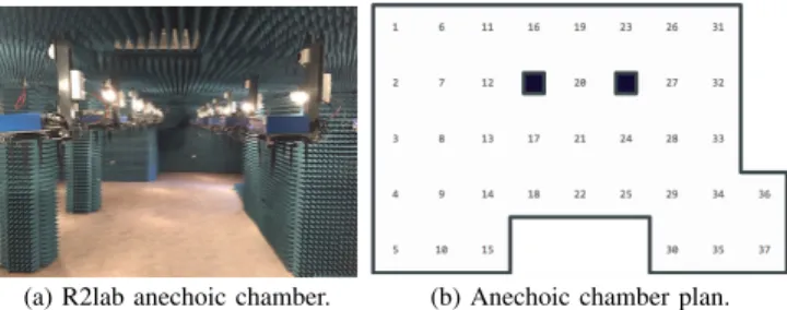
(a) R2lab anechoic chamber. (b) Anechoic chamber plan. Fig. 6: Inria Sophia Antipolis’ faradized anechoic chamber (R2lab) with 37 Wi-Fi nodes equipped with 3-elements ULA and Intel 5300 cards. The antennas are placed under the nodes (blue boxes) to have clear line-of-sight (LoS) communication between nodes.
up our wireless cards in the injection mode, which avoids the need of association with an AP and allows raw Wi-Fi packets transmission. All the packets are processed at a central server where the necessary phase corrections are conducted. The transmission is controlled by disabling the antenna selection algorithm and by specifying the desired number of antennas, streams and transmission technique (SM). The rotation of the antenna was made possible by using extension cables that connect the coplanar transmitter and receiver antenna arrays to the access points.
We conducted our experiments in two environments: an office room and the R2lab anechoic chamber [17]. The latter is a remotely accessible testbed equipped with 37 Wi-Fi nodes that offers a controlled environment with a limited number of reflectors consisting of other nodes in the vicinity. On the other side, the office room contains a large number of scatters, reflectors and other multi-path sources. It also suffers from co-channel and near-channel interference.
A. Joint AoA and AoD and phase correction
a) AoA and AoD estimation and phase correction: We showcase the efficacy of phase correction by comparing angle estimations for the direction of arrival and departure (experiment conducted in R2lab). In Fig. 7a, we can observe clear reduction of estimation error of the true bearing for the angle of arrival after applying the RF oscillator phase offset correction (the red curve). In Fig. 7b, we can observe that the compensation of the aforementioned phase shifts also reduces the angle of departure estimation error.
b) LoS scenario in R2lab anechoic chamber and Office room: We showcase measured data from a communication scenario in a controlled and non-controlled environment. It consists into a 2-antenna transmitter and a 3-antenna receiver in clear line of sight with distances within 3m. Fig. 8 represents the error CDF for AoA and AoD in both environments after applying the calibration and phase correction steps. As expected from the controlled environment (R2lab) we observe better accuracy, fewer errors mainly due to the limited number of multipath clusters and obstructions. The errors are limited in both cases to at most 2.5◦. In Fig. 8, we can observe that the 90th percentile of AoA and AoD error are respectively 0.4◦ and 0.7◦ in R2lab and 1.4◦ and 1.2◦ in the office.
c) Obstructions and estimation accuracy: In order to study the effect of obstruction on the accuracy of AoA and
(a) Pseudospectrum for AoA estima-tion before and after phase correcestima-tion.
(b) Pseudospectrum for AoD estima-tion before and after phase correcestima-tion. Fig. 7: AoA and AoD before and after phase correction.
Fig. 8: AoA and AoD error CDF.
Fig. 9: AoA and AoD boxplot error due to obstruction and human activity.
Fig. 10: Rotation angle and distance error CDF to a reference IMU.
AoD, we conduct an experiment in the office by applying 2 types of obstructions (1) cardboard and polyester objects and (2) human activity near the transmitter and receiver. Fig. 9 shows that these types of obstructions slightly impact the AoA and AoD estimations.
d) Rotation estimation: For verifying the accuracy of rotation estimation, we conducted experiments with a maxi-mum distance of 3m between the transmitter and the receiver in the office area. Fig. 10 shows a 90-th percentile arc distance error of 4mm when taking an IMU as a reference. Knowing that IMUs suffer from heading estimation errors, we expect to have less errors in rotation angle estimates than what is shown in Fig. 10 if absolute reference is available. Distance error is at the millimeter level.
VI. CONCLUSION
We described ORION, a system that can jointly estimate the angle of arrival and the orientation of a Wi-Fi terminal
using unmodified off-the-shelf Wi-Fi devices. We proposed a series of phase correction techniques for both AoA and AoD estimations, and we applied a joint estimation of both param-eters to enhance the accuracy. As measurements usually suffer from statistical noise and other inconsistencies, we propose the use of correction mechanisms for outlier removal and noise reduction. ORION exploits MIMO techniques widely adopted in Wi-Fi equipments such as spatial multiplexing which makes it deployable in practice. We evaluated our system to be accurate for a joint AoA and orientation estimation in both controlled and uncontrolled environments. We plan to enhance ORION for estimating the pitch and the roll using 2D antenna arrays, and by using estimation algorithms robust to multipath environment for instance EM and SAGE. Detailed information and scripts useful to reproduce the experiments made on the R2lab anechoic chamber are available at URL https: //www-sop.inria.fr/teams/diana/orion/.
ACKNOWLEDGMENTS
The R2lab wireless testbed at Inria has been funded by the ANR Equipex FIT 6165. This work has been partly funded by the Labex UCN@Sophia.
REFERENCES
[1] S. Souvik et al. You Are Facing the Mona Lisa: Spot Localization Using PHY Layer Information. In ACM MobiSys, pages 183–196, 2012. [2] Y. Zheng et al. From RSSI to CSI: Indoor Localization via Channel
Response. ACM Computer Survey, 46(2), Dec 2013.
[3] J. Gjengset et al. ArrayPhaser: Enabling Signal Processing on WiFi Access Points. RN, 04, 2014.
[4] D. Vasisht et al. Decimeter-Level Localization with a Single WiFi Access Point. In ACM NSDI, pages 165–178, Santa Clara, CA, 2016. [5] Y. Xie et al. Precise Power Delay Profiling with Commodity WiFi. In
ACM Mobicom, pages 53–64, New York, NY, USA, 2015.
[6] M. Kotaru et al. SpotFi: Decimeter Level Localization Using WiFi. In ACM SIGCOMM, London, UK, Aug 2015.
[7] J. Xiong et al. ArrayTrack: A Fine-Grained Indoor Location System. In ACM NSDI, Lombard, IL, USA, Apr 2013.
[8] K. Liu et al. Attitude determination for unmanned aerial vehicles via an antenna array. In IEEE WSA, 2012.
[9] T.F.K. Cordeiro et al. Improved Kalman-based attitude estimation framework for UAVs via an antenna array. DSP, 59:49 – 65, 2016. [10] A. Mariakakis et al. Sail: Single access point-based indoor localization.
ACM MobiSys, pages 315–328, New York, NY, USA, 2014. [11] E. C. L. Chan et al. Orientation-based Wi-Fi positioning on the google
Nexus One. pages 392–397, IEEE WiMob, Oct 2010.
[12] Z. Zhang et al. I Am the Antenna: Accurate Outdoor AP Location Using Smartphones. ACM MobiCom, New York, NY, USA, 2011. [13] AFZAL et al. Multi-magnetometer based perturbation mitigation for
indoor orientation estimation. Navigation, 58(4):279–292, 2011. [14] H. Mohd et al. Indoor Human Localization with Orientation Using
WiFi Fingerprinting. ACM ICUIMC, New York, NY, USA, 2014. [15] C. Rohrig and F. Kunemund. Estimation of position and orientation of
mobile systems in a wireless LAN. IEEE Decision Control, Dec 2007. [16] J.J. Leonard et al. Mobile robot localization by tracking geometric
beacons. IEEE T-RO, 7(3):376–382, Jun 1991.
[17] Inria. R2lab: Reproducible Research Lab. http://fit-r2lab.inria.fr/. [18] R. Schmidt. Multiple emitter location and signal parameter estimation.
IEEE TAP, 34(3):276–280, Mar 1986.
[19] E. Perahia et al. Investigation into the doppler component of the ieee 802.11n channel model. pages 1–5, Dec 2010.
[20] D. Halperin et al. Tool Release: Gathering 802.11N Traces with Channel State Information. ACM CCR, 41(1):53–53, Jan 2011.