HAL Id: hal-01060309
https://hal.inria.fr/hal-01060309
Submitted on 3 Sep 2014
HAL is a multi-disciplinary open access
archive for the deposit and dissemination of
sci-entific research documents, whether they are
pub-lished or not. The documents may come from
teaching and research institutions in France or
abroad, or from public or private research centers.
L’archive ouverte pluridisciplinaire HAL, est
destinée au dépôt et à la diffusion de documents
scientifiques de niveau recherche, publiés ou non,
émanant des établissements d’enseignement et de
recherche français ou étrangers, des laboratoires
publics ou privés.
Execution of Heterogeneous Models for Thermal
Analysis with a Multi-view Approach
Amani Khecharem, Carlos Gomez, Julien Deantoni, Frédéric Mallet, Robert
de Simone
To cite this version:
Amani Khecharem, Carlos Gomez, Julien Deantoni, Frédéric Mallet, Robert de Simone. Execution
of Heterogeneous Models for Thermal Analysis with a Multi-view Approach. FDL 2014 : Forum on
specification and Design Languages, Oct 2014, Munich, Germany. �hal-01060309�
Execution of Heterogeneous Models for Thermal
Analysis with a Multi-view Approach
Amani Khecharem, Carlos Gomez, Julien DeAntoni, Fr´ed´eric Mallet and Robert de Simone Univ. Nice-Sophia Antipolis, CNRS, UMR7271, I3S F-06900 Sophia Antipolis
INRIA, F-06902 Sophia Antipolis
Email:{julien.deantoni, frederic.mallet}@unice.fr, {amani.khecharem, robert.de simone}@inria.fr
Abstract—To deal with the high complexity of embedded systems, engineers rely on high-level heterogeneous models that combine functional and non-functional aspects, hardware/soft-ware artifacts, structural and behavioral descriptions. PRISMSYS is a system-level multi-view modeling framework, which provides a means to specify functional and non-functional aspects in interrelated views. Each concern/view is addressed separately with a dedicated set of models and correspondence rules, maintaining the semantic consistency between those different views. The behavioral specification mixes UML state machines with equational models defined as SYSML parametric diagrams. To supply a complete non-functional property-aware simulation environment, it is mandatory to formalize 1) the execution semantics of theUML state machines, 2) the SYSML parametric diagrams and 3) the coordination between them. This is achieved by using CCSL, the Clock Constraint Specification Language, to provide an event-based semantics for each model and their coordination. The proposed co-simulation framework combines TIMESQUARE, a discrete event simulator for CCSL, and Scilab, a tool for numerical computation. The framework is illustrated on a CPU thermal manager case study with a joint simulation of both its functional and non-functional models.
Keywords-Multi-View, Heterogeneous Models, UML. I. INTRODUCTION
The design of embedded systems requires a strict con-formance to the non-functional requirements, such as heat dissipation, energy consumption, safety or time performance. These properties are usually addressed (i.e., modeled and analyzed) by experts of different domains. Experts have their own languages and tools to describe the system modeled from their own point of view. Nevertheless, these expert’s models are strongly connected; the behavior of a model could impact the behavior of the other ones. For instance, powering a component off in a power management model affects the functional behavior and the performances of the component in a functional description model.
The recent IEEE 42010 standard [1] proposes a common vocabulary to capture the different views of heterogeneous models. Correspondences are used to associate domain ele-ments from different views. For instance, in a thermal view, if the temperature of a CPU is reaching the maximum acceptable temperature, the controller may reduce the clock frequency and voltage level (or turn the CPU off) to avoid damaging the CPU. This syntactic link between a non-functional property in a specific view and its impact on the other view should also be considered from a semantic point of view.
More generally, the behavior specification of an embedded system should explicitly take the non-functional properties into account to provide a correct representation of the sys-tem behavior. While it may eventually be implemented by using specific sensors, there is a need for early modeling and co-simulation of two types of behavior: one based on a discrete (logical) time representing the functional behavior of the system; and another one based on continuous time representing the evolution of non-functional properties and/or other physical phenomenon.
PRISMSYS[2] proposes to tack the semantics of the MoCs on top of traditional engineering models based on the UML
(Unified Modeling Language [3]) or one of its specializations like SYSML [4] or MARTE [5]. PRISMSYS [2] also proposes to keep the semantics of the MoC explicit and separate from the functional model to ease its extraction, modification and analysis. PRISMSYS implements the IEEE 42010 standard. It relies on UML and SYSML to capture both functional and non-functional properties [6].
In this paper, we propose an operational framework for the joint simulation of both the discrete and continuous parts of the PRISMSYS model. The semantics of PRISMSYS models is described using the Clock Constraint Specification Language (CCSL [7], [8]). CCSL is a formal declarative language for discrete logical time specification amenable to analysis and simulation in the associated tool TIMESQUARE[9]. We have built a dedicated backend for TIMESQUAREto drive, not only the execution of the discrete part of the model, but also of the continuous part. This particular aspect is delegated to Scilab tool [10]. We illustrate the approach on a thermal manager and we present the model, explain the way the backend is built and give some execution results.
The paper starts with discussing related works (Section II) on both heterogeneous modeling and modeling of thermal aspects. Then, Section III briefly recalls the fundamentals of PRISMSYS. Section IV describes the execution semantic of PRISMSYS for heterogeneous execution based on CCSL.
CCSL is introduced on-the-fly, with only the minimum mate-rial required. Finally, the implementation of TIMESQUARE’s backend for Scilab is described in Section V and illustrated on a case study in Section VI. Section VII concludes with possible extensions.
II. BACKGROUND AND RELATED WORK
A. Heterogeneous Modeling
The joint use of different Models of Computation (MoCs) [11], [12], [13] for a single system is known as
Het-erogeneous Modeling. A MoC (e.g., Synchronous Data Flow, Finite State Machine or Continuous Time) makes explicit the execution semantics applied to a specific syntactic model. Several approaches and tools address the problem of modeling and simulation of heterogeneous models.
Hybrid automata [14] offer a theoretical framework to combine discrete and continuous phenomena. An attempt to mix Hybrid Automata and CCSL has been conducted [15]. However, hybrid automata do not offer any specific support for combining heterogeneous syntactic models (dataflow, equa-tions, control) or for a clean separation of preoccupations or views. This is addressed here.
Ptolemy II [16] relies on a generic actor model to capture hierarchical heterogeneous models. The model of computation (MoC) and its interactions with other MoCs are described in a so-called director that conforms to a predefined Java API.
Ptolemy II is widely used and has inspired many derived products or evolutions. There are two main differences with our proposal. First, we rely on UML and SYSML to capture the structural information instead of a pure actor model. Second, the synchronization and scheduling constraints are given explicitly in CCSL rather than being hidden inside the Java code and mixed with the functional description. Making the MoC explicit and separate allows for reasoning on its properties.
BIP [17] is an interesting alternative that supports explicit heterogeneous interaction models. The behavior is described using timed automata, then several interaction schemes can be used. Contrary to BIP, PRISMSYS does not require to use state-based representation and may also rely on data flow models or equational models to capture continuous aspects. This increase of expressiveness comes at the cost of decidability results.
There are several works that focus on the interactions be-tween discrete and continuous time, like MatLab/Simulink or Scilab/Scicos. Amongst the solutions that support synchronous models of computation, Zelus [18] provides a nice integration with Lustre. However, in all these solutions, the functional and interaction models are intertwined and hidden as design choices inside the tool. Our proposal is to make the choices explicit in the model (like using a fixed-step solver with a given step) and use the model to drive the tools.
On the engineering side, SYSML [4] introduces the notion of parametrics to capture acausal models. This is adequate to describe continuous functions or relations and PRISMSYS heavily rely on this new construct to capture the thermal and power-related information. Our proposal is to define an execution framework to execute such models.
B. Non-Functional (Thermal) Modeling
Non-functional properties are more and more important in many embedded systems, they must be consequently taken into account during the design process.
Most of the time, non-functional properties are modeled (and analyzed) by using specific tools. For instance, to analyze the impact of temporal properties on the system schedulability, experts in time performance use tools such as Cheddar [19] where the focus is made on specific temporal properties while the other aspects of the application and its architecture are largely abstract away. Additionally, to study the thermal aspects of a system, temperature experts employ tools like
Hotspot [20] or Aceplorer [21]. Once again, the tools give many details on the properties that deal with their specificity (in this case, the thermal equations), but the other parts of the system remains largely abstract.
In consequence, the study of several non-functional prop-erties requires the duplication of some parts of the system model in these dedicated tools. Due to the strong abstraction of specific parts, these tools cannot be used standalone. For instance, since Aceplorer does not model the system functional behavior, it needs an execution scenario, generated from a functional system simulation, to activate the elements of its power model and consequently evaluate the power consump-tion of the system. In the same way, Hotspot is based on the Compact Thermal Model [22], which defines the model of a the thermal features of the system component and their thermal influence over their neighbors. This model does not represent the system activity needed by Hotspot to generate the temperature layout of the system.
One current problem comes from the use of dedicated con-troller (e.g., the power manager of an OMAP platform [23]) whose goal is to change the functional behavior in reaction to non-functional property evolution. For instance, because the power consumption of a chip is exponentially increasing with its temperature, a power controller can choose to slow down (or to stop) a chip when its temperature is exceeding a specific threshold. In this case, the functional simulation sets the chip activity according to the chip temperature, but the chip temperature in tools like Aceplorer or Hotspot requires the chip activity. Therefore, there is a cyclic dependency between the execution of the tools that can be solved by a co-simulation of the domain specific models (or tools).
As a consequence, it is important to define a central (multi-view) model where the behavioral dependencies are made explicit. The semantics of these dependencies can thus be taken into account to coordinate the domain specific models. To specify these dependencies, we define a system-level frame-work where the behavioral semantics of each part takes into account its links to the other parts of the system. We focused here on the co-simulation of these models to show the benefits of the approach. This framework is named PRISMSYS.
III. PRISMSYS: AMODELING MULTI-VIEW FRAMEWORK FOR SYSTEMS
PRISMSYS is a multi-view framework for modeling sys-tems, focused on the description and analysis of functional and non-functional aspects. In this framework, a view characterizes the aspects of a specific domain relevant for the system. For instance, time performance model, power model and
temperature model are different views of the same system, and they characterize aspects such as time, power consumption and temperature evolution.
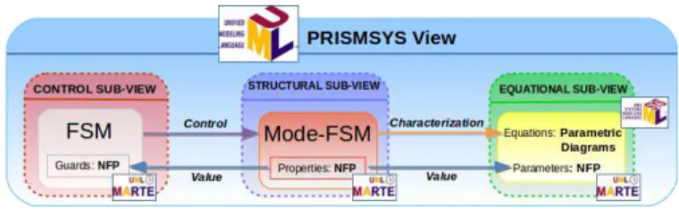
Figure 1 depicts the main elements of PRISMSYS. A
PRISMSYS viewcontains up to three sub-views: Control,
Struc-tural and Equational. The structural sub-view states domain specific elements, which can possibly be an abstraction of elements that exist in another view. These elements define the non-functional properties relevant from the domain point of view. The behavior of these elements is described by Finite State Machine (FSM). The FSM abstracts the operation modes of the element in a specific domain and the transitions are sensitive to events generated from the control sub-view. We use UMLcomponents to represent these elements and MARTE
Non-Functional Properties (NFP) to type the properties defined in the sub-view elements. The equational sub-view specifies the equations that characterize the properties stated in the structural sub-view. We use SYSML Parametric Diagram to represent the equational sub-view. The control sub-view com-mands the execution of the elements specified in the structural sub-view. A way to specify these views is to use controllers, elements which behavior is stated as a FSM. In contrast to the structural sub-view FSM, the transitions of the controller FSM are sensitive to the evaluation of a condition, i.e., to a guard. Once the transition is fired, an effect is produced, sending an event to the corresponding FSM in the structural sub-view. To distinguish between both FSMs, we employ the term
mode-FSM to reference the FSM specified in structural sub-view.
Fig. 1. PRISMSYSView
The consistence between different views is defined through
correspondences. A correspondence is a syntactic association between elements of two different views, e.g., the abstraction of an element from a first view characterizes this element from another point of view. Besides specifying associations between views, sub-views also own relationships between them. We named them sub-correspondences. For instance, PRISMSYS provides a state-equation association through the
charac-terization sub-correspondence. This sub-correspondence was defined since it is not possible to specify when a SYSML equation is active or not by activating a state in a FSM.
Equivalence is another sub-correspondence used to bind the structural sub-views properties to the value calculated on the equational sub-view. To address the control events of the mode-FSMs explicitly, a control sub-correspondence must be specified. Values tested in the FSM guards are extracted from the structural view properties by using the data
sub-correspondence.
A PRISMSYS view combines the execution of two kinds of MoCs: FSMs based on a discrete (logical) time, and the equations based on a Continuous Time. This MoC combination could be homogeneous (FSM and Mode-FSM) or
heteroge-neous(Mode-FSM and Continuous Time). To give an execu-tion semantics to FSM, Mode-FSM, Continuous Time and the coordination between them, PRISMSYS defines the relevant events of the models together with constraints that specify the causal relations and synchronizations. Each relevant action in a MoC is expressed as an event and we use CCSL [24], an event constraint language, to represent the allowed sequences of actions conforming to the selected MoC.
IV. PRISMSYS EXECUTIONSEMANTICS
PRISMSYS behaviors, which initially are described by a static definition (meta-model), need a formal way to express their actions associated with their static elements. CCSL pro-vides the needed concepts to express the actions of these behaviors allowing the association action-element and the behavioral analysis by simulation. First, we define the FSM execution semantics. Second, we state the execution semantics in Continuous Time. Finally, we describe the coordination between FSMs and Continuous Time.
A. Constraint Clock Specification Language
Execution Semantics of PRISMSYS relies on the CCSL
formalism. We recall briefly the basic facts on CCSL, which
is presented at large in [7], [8].
In CCSL, it is possible to define Clocks, which are possibly infinite ordered sets of instants. These clocks represent relevant changes in a system, on which constraints can be specified. A clock can be either chronometric or logical. The former is employed to specify a constraint associated with a physical dimension like the physical time or distance. The later defines a terminology referring to events (if events are sequences of event occurrences, as clocks are sequences of clock ticks). Distinct clocks can be independent (fully asynchronous), or partially ordered. The goal is that, after completion of design the specification represents a set of partially ordered clocks and eventually, at runtime, all clocks are mapped onto a single, most fundamental and totally ordered master clock representa-tion simularepresenta-tion/execurepresenta-tion step, but before that, designing with independent logical clocks is usually highly beneficial.
Clocks (and clock ticks) may enjoy two basic types of ordering relations: a clock is faster than another one (based on tick precedence), or a clock may be subclock of another one (based on tick simultaneity). The former relation is denoted a ≺ b, the latter a ⊂ b, where a and b are clocks. Relations, a = b (all ticks are simultaneous) or a # b (no ticks are common), can also be stated.
Based on those types of relations, more sophisticated con-straints may be introduced. A sample is given:
• a ∼ b: a and b tick once in turn,
• a❉b: defines a new clock that ticks with b if there was
• a H mask: defines a new clock that is subclock of a
but only ticks in a place wheremask, a periodic binary word, reads 1.
We employ these CCSL relations and expressions to define the execution semantics of FSM, the evaluation of equations (Continuous Time) and the coordination between them. The execution semantics of finite state machine are defined on the
UMLmetamodel by anECL (Event Constraint Language [25]) specification. Consequently, the CCSL specification can be automatically generated for a specific FSM model.
B. Finite State Machine Semantics
In a FSM, there are various relevant events that occur during its execution. Most of the FSM concepts are associated with one or more events that describe a particular FSM execution change, e.g., the entering in a state or the firing of a transition. These events are represented in CCSL by clocks. Table I
summarizes the clocks defined to represent the relevant actions of a FSM.
Clock Action
init Initializing the execution of FSM
senter Entering state s
sleave Leaving state s
f ire tij Firing transition tijfrom sito sj
guardij Ticking once the tijguard evaluation is true
triggerij Receiving a trigger event on tij
ef f ectij Generating an Event once tijis fired
TABLE I
CLOCKS REPRESENTING THE RELEVANT ACTIONS IN AFINITESTATE
MACHINE.
We give a precision about the FSM model, we constrain that a transitiontij is sensitive to either aguardij or atriggerij,
however not both of them. If a guard is defined, thenguardij
clock is stated, else triggerij is specified.
Once the FSM clocks are defined, we identify the con-straints on these clocks to describe the FSM execution se-mantics. We start defining the activation of a specific state. A state is active between the corresponding entering and leaving occurrences. In other words, the state s is active when the kth
occurrence of senter clock ticks and it stops
being active when the kth
occurrence of sleave ticks. A state
cannot be transitory, i.e., the senter and sleave ticks cannot
be simultaneous. Moreover, a state cannot be activated if it is already active. Consequently, we use an Alternate relation between senter and sleave in CCSL for all the states of FSM
as follows:
senter ∼ sleave (1)
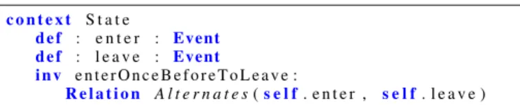
Equation 1 is specified in ECL by an event invariant on the concepts of UML State Machine as illustrated in Figure 2.
This ECL constraint defines two properties whose type is
Event (enter and leave) specified in the context of the State
UML concept. The relation between both events is Alternate,
i.e., this ECL specification represents senter, sleave and their
relation for all the State instances in a model. While not
c o n t e x t S t a t e
d e f : e n t e r : Event d e f : l e a v e : Event
i n v e n t e r O n c e B e f o r e T o L e a v e :
R e l a t i o n A l t e r n a t e s(s e l f. e n t e r , s e l f. l e a v e )
Fig. 2. ECL specification of the UML State activation.
detailed in this paper, all the CCSL constraints were also specified in ECL in order to automate the generation of the
CCSL specification for any FSM model.
According to the execution semantics of FSM [26], a transition tij from a state si to a state sj is fired if two
conditions are achieved: si is active, and either thetij guard
evaluation is true or triggerij ticks. However, the instant
when the guard is evaluated is not specified. Because it affects the timing properties, it is of primary importance for a state machine of an embedded system to define when the guard is evaluated. In PRISMSYS, we explicitly define a chronometric
clock named eval that specifies the period when the guard is evaluated. This clock is the same for all the guards in the system and its period must be chosen according the non-functional property dynamic (see section IV-D). Hence, when the evaluation of thetij guard condition returns true,guardij
occurs. Considering that si is active and guardij ticks, then
thetij transition is fired. In contrast, if a transition is sensitive
to a trigger event, the tij transition is fired when triggerij
ticks. We specify the relationship of these clocks by using
CCSLexpressions. We present theCCSLconstraints that define when to fire thetij transition byguardij:
f ire tij = [(sienter❉guardij) sileave] •f ire tij
this expression can be read as: a transition tij is fired if
guardij ticks while the state is active (i.e., after a sienter
occurrence and up to an occurrence ofsileave).
The statesi stops being active (i.e.,sileave ticks) when one
of its outgoing transitions occurs. The relationship between the leaving of a state and the firing of the outgoing transitions is specified as follows:
sileave =
[
t∈toutsif ire t
wheretoutsi is the set of outgoing transitions fromsi.
When a transition is fired, the targeted state is entered simultaneously, i.e.,entering state sj coincides with the firing
of all the incoming transitions. This is specified as follows: sjenter =
[
t∈tinsjf ire t
wheretinsj is the set of incoming transitions tosj.
If the transitiontij has an action, theef f ectij clock occurs
simultaneously with the transition firing. This relationship is specified by:
ef f ectij = f ire tij
TheUMLstate machines must have at least one initial state. We constrain them to have one and only one initial state. The clock init is specified to start the FSM execution by activating
the initial state. We only need one tick in init to activate the initial state. Thus, we state init inCCSL as follows:
init = initH1(0)w
this equation forces init to tick only once.
The init clock must be associated with the initial state. Considering thatsinitis the initial state of the FSM, we define
its activation as follows:
sinitenter = init
By using these rules, we defined the event based semantics of the UML state machine. It is then possible to reason about a specific state machine and to simulate it in TIMESQUARE, obtaining a timing diagram and/or a diagram animation. It is now mandatory to define the continuous time execution semantics.
C. Continuous Time Execution Semantics
In the considered systems, non-functional properties evo-lution often depend on physical time. There are two main families of continuous time solvers, the fixed-step solvers and the variable step solvers. A fixed-step solver evaluates the equation of the modeled process periodically with a predefined step size. The disadvantage of such solvers is that they can hide some discontinuities in the modeled process if the step size is too big. The variable step solvers adapt the step size to the dynamic of the modeled process in order to avoid hiding such discontinuities. This is of great importance when the goal is to provide an accurate representation of the modeled process. In our case, we model by equations the evolution of non-functional properties according to time. One important goal of this work is to allow the prototyping of non-functional property managers. Eventually, these managers will retrieve the value of the corresponding non-functional properties by using (periodic) sensors. Consequently, we do not try to obtain the best representation of the non-functional property evolution, but rather a representative view of the process at specific points in time, as seen by the managers. Therefore, we can use either fixed-step or variable-step solvers but we do not use zero crossing functionality and we explicitly specify in the
UMLmodel the point in time when the value from the process are retrieved. To ease the implementation we used for now only fixed-step solvers so that the points in time when the value from the process are retrieved are periodic and correspond to the solver fix step.
In the model, to specify the step size used by the solver, we employ a chronometric clock from MARTE. In CCSL, this is encoded by discretizing a dense clock (i.e., a clock in which whatever pair of two instants you choose, there exists always one instant between these two instants). We use the physical time dense clock defined inCCSLand we name the discretized clock step. At each occurrence of step, the active equations specified in the model are evaluated by the continuous time solver. In CCSL, the step clock is defined by:
step , physicalT ime discretizedBy ∆t (2)
where ∆t is the step size as defined in the UML model and used by the fixed-step solver.
Once the FSM and Continuous Time execution semantics are defined, we must coordinate the actions of both semantics to achieve a complete execution of a PRISMSYS view.
D. FSM and Continuous Time Coordination
We provided the event based semantics for the UML state machine (FSM) and for the SYSML parametric diagram (Continuous Time). Control and structural sub-views follow the FSM semantics and the equational sub-view follows a Continuous Time semantics. Instead of providing a tailored semantics for a new model mixing both semantics, such as in an hybrid automata [26], we propose to define the semantics of the syntactic association between the different sub-views (named sub-correspondences in PRISMSYS). The coordination semantics is also specified inCCSL.
In the structural sub-view, the FSM are representing some mode automata. The transition between two modes is caused by the reception of an event sent from the control sub-view. Therefore, there is a correspondence between the output events generated from the control sub-view and the events associated with the mode transitions. This correspondence is syntactically represented by control connectors between control and structural sub-views.
From the behavioral semantic perspective, a control event generated from the FSM of the control sub-view can cause a mode transition in the mode automata of an element in the structural sub-view. This relation can be tailored to be synchronous, purely causal or even timed. Here we chose that the sending and the reception of an event occurrence is simultaneous. By using CCSL, if an event occurrence is transferred by a control connector from a transition tij to the
trigger of a mode automata (triggermode automata) we enforce
the following coincidence relation:
ef f ectij = triggermode automata
we read this expression as a control event, produced dur-ing the transition in a control FSM (ef f ectij), coincides
with the trigger of a transition in the mode automata (triggermode automata).
In PRISMSYS, the mode automata are used to specify the modes under which there are different distributions that govern the evolution of a non-functional property. For instance the instantaneous consumption of a CPU depends on its activity (e.g.,sleep, idle or active). These evolutions are specified by different equations that are enabled or not according to the active state of a mode-FSM (see section III). To represent this semantics, a mode-FSM and an equation are syntactically linked by a characterization sub-correspondence. When a mode becomes active (i.e., clock senter ticks), the associated
equation is enabled. When the mode is left, (i.e., clocksleave
ticks), the corresponding equation is disabled. Of course, for the model to be consistent, a non-functional property should be at least defined by one equation during a run.
We have two chronometric clocks in the system. The one used for the evaluation of the guard and the one that defines the fix step of the solver. To avoid the evaluation of the guards without a new value computed by the equation, the chronometric clock used for the solver step must be the same or faster than the one used to evaluate the guards. We express this coordination in CCSL as:
step 4 eval (3)
where eval is the clock whose instants command the evalu-ation of the guards and step is the fix step of the solver. If these two clocks are simultaneous, it is mandatory to evaluate the equations before the evaluation of the guards to respect the causality (even if instantaneous in this case). It guarantees that the non-functional properties used in the guards have the latest value resulting from equation evaluation.
Now that the execution semantics of PRISMSYS is specified, the remainder of the paper presents the associated implemen-tation.
V. PRISMSYS MODELCO-SIMULATION
TIMESQUAREis an Eclipse and model-based environment for the specification, analysis and verification of causal and temporal constraints. Particularly, TIMESQUAREallows defin-ing, analyzing and verifying a CCSL specification. Neverthe-less, this tool is not adapted to evaluate equations (e.g., power and temperature equations). Therefore, we use Scilab [10], an open source tool for numerical computation, as a fixed-step solver for the evaluation of the equations. To coordinate the TIMESQUAREsolver with the Scilab solver, we implemented a TIMESQUAREbackend that acts like a “connector” between these tools. We named it T2BACKEND FORSCILAB.
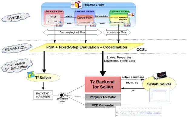
Figure 3 depicts an overview of this implementation. It shows three dependent domains: the one on top is the
PRISM-SYSmodel, detailed in Section III. The one at bottom describes the TIMESQUARE and Scilab co-simulation and the one in the middle defines the PRISMSYS semantics to execute and to coordinate the behavior of the PRISMSYS model. We focus in this section on the block at the bottom, the T2BACKEND FOR
SCILAB.
TIMESQUARE offers the possibility to add user-defined backends that trigger specific actions on selected event occur-rences or relations. These new backends can be added to the
backend managerby using an eclipse extension point. During a simulation, the backend manager receives the status of each clock (it ticks or not) at each simulation step. It also receives the status of relations (causality and coincidence) as well as the status of the assertions (violated or not). A developer can create its own backend that subscribes to some of these events. TIMESQUAREis already distributed with some backends like the VCD backend that draws the timing diagram of the clocks during the simulation and the Papyrus Animator that animates the elements of an UML model specified in Papyrus1. Alike, by using the backend manager and connecting to the specific
1http://www.eclipse.org/papyrus/
extension point, we implement T2BACKEND FORSCILABas an Eclipse Plug-in to bind the TIMESQUARE solver module with the Scilab solver. This back-end receives the status of the clock (it ticks or not) at each simulation step and consequently configures the Scilab solver according to the information in the
UMLPRISMSYSmodel and drives the Scilab solver to evaluate the equations during the simulation. The user can visualize the value of the non-functional properties thanks to the Scilab graphic window called by the Scilab solver.
The solver configuration consists in the extraction of dif-ferent equations from the model as well as the extraction of the chronometric clock that defines the solver step size. It is mandatory for the backend to register to the entering and leaving clock of all the mode-FSM states linked to an equation in order to add or remove it from the Scilab solver accordingly. This backend also commands the evaluation of the guards, therefore such pieces of information must also be extracted from the PRISMSYS model. During the simulation, the T2 BACKEND FOR SCILAB receives the status of each relevant clocks. When an entering state (sienter) clock ticks, T2
BACKEND FORSCILAB adds the equation(s) associated with
the active state. When the step clock ticks, the active equations are evaluated by the Scilab solver. The result of the evaluation is plotted in a Scilab plot window and stored in the backend. For each step occurrence, the guards are evaluated. If a guard is evaluated to true, T2 BACKEND FOR SCILAB forces the associated guard clock occurrence in the TIMESQUAREsolver (see guardij in Section IV). Such occurrences can cause a
change of the controller state, and then a mode change. We can note that the guard evaluation is done for each step occurrence and not necessarily immediately when the parameter exceeds the thresholds. It emphasizes the importance to select the appropriated solver step size in order to react soon enough to the evolution of the non-functional properties.
VI. CASESTUDY: CPUTHERMAL CONTROLLER
The case study shows how a thermal controller can be prototyped by using PRISMSYS. The temperature, a non-functional property, must be monitored in order to reduce the power consumption, extending the battery charge and fulfilling the temperature requirements. The CPU is the component on which we focus in this case study. We define a CPU muti-view model by using PRISMSYS. In Figure 4, we present a simplified version of the thermal view model. The figure depicts the three PRISMSYS behaviors (control, modes and equations).
The structural sub-view of this figure represents the abstrac-tion of a CPU from a thermal point of view. It describes a non-functional property representing the temperature (T). The equational sub-view defines the equations that characterize the evolution of the CPU temperature. The Control sub-view specifies a thermal controller, which changes the activity of the CPU according to its temperature to avoid damages.
The CPU thermal behavior is represented by two modes:
COOLING and HEATING. Each mode corresponds to a dif-ferent temperature evolution. COOLING indicates the CPU
Fig. 3. T2 BACKEND FORSCILABOverview on a PRISMSYS thermal view case study.
Fig. 4. Case Study: CPU Thermal Controller
temperature is decreasing. In contrast, HEATING means that the CPU temperature is increasing. In order to define the evolution of the temperature, an equation, specified in the equational sub-view, is associated (point 2 in Figure 4). Thus, we associate the HEATING mode with the equation dT /dt = −0.1 ∗ (T − 100) and the COOLING mode with the equationdT /dt = −0.1∗(T −30) where 100 is the temperature maximum for the CPU and 30 is its minimal idle temperature. The unit of both temperatures is◦C.
The change between two modes occurs when the transition between them is fired. Transitions are sensitive to associated events sent from the control sub-view (point 1 in Figure 4). The control sub-view contains a thermal controller whose task is to manage the temperature evolution of the CPU. The
controller behavior is another state machine of two states:
LOW and HIGH. LOW represents that the CPU temperature is below the recommended temperature. HIGH expresses the temperature exceeds the maximum recommended value. In contrast to the CPU thermal FSM, the transition of the controller is sensitive to the evaluation of guards. In this case study, guards evaluate if the temperature surpasses 85◦C or
is lower than 80◦C (point 3 in Figure 4). Once a transition
is fired, a specific event is sent to the CPU thermal FSM in order to change its mode and thus activate the equation to be evaluated.
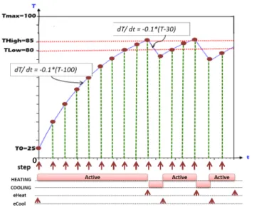
Figure 5 depicts the evolution (plotted in Scilab) of the tem-perature T according to the time t. When the simulation starts,
i.e., at t=0, T2 BACKEND FOR SCILAB extracts the clocks associated with modes COOLING and HEATING and the step clock. T2BACKEND FORSCILABalso identifies and extracts the thermal equations. In our thermal model, we assume that the ambient temperature is 25◦C. Thus, the T
IMESQUARE
simulation starts at25◦C and the activating LOW and
HEAT-ING states (which are the initial states) are activated. When the temperature exceeds85◦
C, the corresponding transition is fired, the state changes to HIGH and the eCool event is sent to the CPU Thermal Modes (other events, which set the CPU activity to idle in other views, are also sent but not represented here). Such an event causes the leaving of the HEATING mode to enter in the COOLING mode, consequently deactivating the equation dT /dt = −0.6 ∗ (T − 100) and activating the equation dT /dt = −0.6 ∗ (T − 30). In the next simulation steps, the associated COOLING equation is evaluated and the temperature decreases. When the temperature is lower than 80◦C, the controller state machine changes to the LOW state
and the cycle is repeated.
Fig. 5. PRISMSYS ThermalView simulation in Scilab by using T2 BACKEND FORSCILAB.
In Figure 5, we note that the temperature actually exceeds some how the threshold defined in the guard. This is due to the periodic monitoring of the temperature and the periodic evaluation of the guard. To limit such phenomenon, one could decrease the step size. However, this phenomenon has to be taken into account during the development of the system.
VII. CONCLUSION AND FUTURE WORK
In this paper, we have presented a simulation framework based on PRISMSYS to execute heterogeneous models that combine functional and non-functional views. We have fo-cused on the execution semantics of the PRISMSYS discrete (logical) time (FSM) and its coordination with the Contin-uous Time model of the non-functional property equations. We have also described the implementation, T2 BACKEND FORSCILAB, a connector between TIMESQUARE and Scilab
to enable the co-simulation of discrete (logical) time and Continuous Time. A simple thermal view model is used to illustrate PRISMSYS and the execution framework. As a future work, we intend to explore further the different correspondence rules between views. Some correspondence rules are mere importation of elements from one view to another one. Other ones are closer to coordination/synchronization rules.
VIII. ACKNOWLEDGEMENT
This work is partially supported by the ANR INS Projects HOPE 0003) and GEMOC (ANR-12-INSE-0011).
REFERENCES
[1] “Systems and software engineering – architecture description,” ISO/IEC/IEEE 42010:2011(E) (Revision of ISO/IEC 42010:2007 and IEEE Std 1471-2000), pp. 1 –46, 2011.
[2] C. Gomez, J. DeAntoni, and F. Mallet, “Multi-view Power Modeling Based on UML, MARTE and SysML,” Software Engineering and Advanced Applications (SEAA), pp. 17 – 20, 2012.
[3] OMG, “OMG Unified Modeling Language,” Object Management Group, vol. v2.4.1, Aug. 2011.
[4] ——, “Omg. systems modeling language (sysml),” Object Management Group, vol. v1.2, Jun. 2010.
[5] ——, “UML Profile for MARTE,” Object Management Group, vol. v1.1, Oct. 2010.
[6] C. Gomez, J. DeAntoni, and F. Mallet, “Power Consumption Analysis Using Multi-View Modeling,” Power and Timing Modeling, Optimiza-tion and SimulaOptimiza-tion (PATMOS), pp. 235 – 238, 2013.
[7] C. Andr´e, J. DeAntoni, F. Mallet, and R. de Simone, The Time Model of Logical Clocks available in the OMG MARTE profile. Springer Science+Business Media, LLC 2010, July 2010, ch. 7, pp. 201–227. [8] C. Andr´e, “Syntax and Semantics of the Clock Constraint Specification
Language (CCSL),” INRIA, Research Report RR-6925, 2009. [Online]. Available: http://hal.inria.fr/inria-00384077
[9] J. DeAntoni and F. Mallet, “Timesquare: treat your models with logical time,” in Proceedings of the 50th international conference on Objects, Models, Components, Patterns, ser. TOOLS’12. Berlin, Heidelberg: Springer-Verlag, 2012, pp. 34–41.
[10] “Scilab Consortium,” Scilab. http://www.scilab.org/, [Sep.10 2013]. [11] S. Edwards, L. Lavagno, E. Lee, and A. Sangiovanni-Vincentelli,
“De-sign of embedded systems: formal models, validation, and synthesis,” Proc. of the IEEE, vol. 85, no. 3, pp. 366–390, 1997.
[12] A. Jantsch, Modeling embedded systems and SoC’s: concurrency and time in models of computation. Morgan Kaufmann (an imprint of elsevier science), 2004.
[13] A. Jantsch and I. Sander, “Models of computation and languages for embedded system design,” Computers and Digital Techniques, IEE Proceedings, vol. 152, no. 2, pp. 114–129, Mar 2005.
[14] T. Henzinger, “The theory of hybrid automata,” in Verification of Digital and Hybrid Systems, ser. NATO ASI Series, M. Inan and R. Kurshan, Eds. Springer Berlin Heidelberg, 2000, vol. 170, pp. 265–292. [Online]. Available: http://dx.doi.org/10.1007/978-3-642-59615-5 13 [15] J. Liu, Z. Liu, J. He, F. Mallet, and Z. Ding, “Hybrid marte statecharts,”
Frontiers of Computer Science, vol. 7, no. 1, pp. 95–108, 2013. [16] J. Eker, J. W. Janneck, E. A. Lee, J. Liu, X. Liu, J. Ludvig, S. Sachs,
Y. Xiong, and S. Neuendorffer, “Taming Heterogeneity - The Ptolemy Approach,” Proceedings of the IEEE, vol. 91, no. 1, pp. 127–144, 2003. [17] A. Basu, M. Bozga, and J. Sifakis, “Modeling heterogeneous real-time
components in bip,” in SEFM, 2006, pp. 3–12.
[18] T. Bourke and M. Pouzet, “Zelus: A Synchronous Language with ODEs,” in 16th International Conference on Hybrid Systems: Computation and Control (HSCC’13), Philadelphia, USA, Mar. 2013, pp. 113–118. [Online]. Available: http://www.di.ens.fr/∼pouzet/bib/
hscc13.pdf
[19] F. Singhoff, J. Legrand, L. Nana, and L. Marc´e, “Cheddar: a flexible real time scheduling framework,” in SIGAda. New York, NY, USA: ACM, 2004, pp. 1–8.
[20] W. Huang, S. Ghosh, S. Velusamy, K. Sankaranarayanan, K. Skadron, and M. Stan, “Hotspot: a compact thermal modeling methodology for early-stage vlsi design,” Very Large Scale Integration (VLSI) Systems, IEEE Transactions on, vol. 14, no. 5, pp. 501 –513, may 2006. [21] Docea Power, “Aceplorer,” http://www.doceapower.com/
products-services/aceplorer.html, [Feb. 7, 2014].
[22] A. Vassighi and M. Sachdev, Thermal and power management of integrated circuits. Springer Science+Business Media, Incorporated, 2006, ch. Thermal and Electrothermal Modeling.
[23] OMAP35x Applications Processor Technical Reference Manual, Texas Instruments, Apr 2010.
[24] E. Andrade, P. Maciel, G. Callou, and B. Nogueira, “A Methodology for Mapping SysML Activity Diagram to Time Petri Net for Requirement Validation of Embedded Real-Time Systems with Energy Constraints,” in Digital Society, 2009. ICDS ’09. Third International Conference on, Feb 2009, pp. 266–271.
[25] J. Deantoni and F. Mallet, “ECL: the Event Constraint Language, an Extension of OCL with Events,” INRIA, Research Report RR-8031, Jul. 2012. [Online]. Available: http://hal.inria.fr/hal-00721169 [26] C. G. Cassandras and S. Lafortune, Introduction to Discrete Event