HAL Id: hal-03044536
https://hal.archives-ouvertes.fr/hal-03044536
Submitted on 7 Dec 2020HAL is a multi-disciplinary open access archive for the deposit and dissemination of sci-entific research documents, whether they are pub-lished or not. The documents may come from teaching and research institutions in France or abroad, or from public or private research centers.
L’archive ouverte pluridisciplinaire HAL, est destinée au dépôt et à la diffusion de documents scientifiques de niveau recherche, publiés ou non, émanant des établissements d’enseignement et de recherche français ou étrangers, des laboratoires publics ou privés.
From soft chemistry to 2D and 3D nanowire arrays with
hard magnetic properties and permanent magnet
applications
Katerina Soulantica, Thomas Blon, Bruno Chaudret, Lise-Marie Lacroix, G.
Viau, Frédéric Ott
To cite this version:
Katerina Soulantica, Thomas Blon, Bruno Chaudret, Lise-Marie Lacroix, G. Viau, et al.. From soft chemistry to 2D and 3D nanowire arrays with hard magnetic properties and permanent mag-net applications. Magmag-netic Nano- and Microwires, Elsevier; Elsevier; Elsevier, pp.185-219, 2020, �10.1016/B978-0-08-102832-2.00007-4�. �hal-03044536�
Version 1, 2019 January 31
From soft chemistry to 2D and 3D nanowire arrays with hard
magnetic properties and permanent magnet applications
Katerina Soulantica, Thomas Blon, Bruno Chaudret, Lise-Marie Lacroix, Guillaume Viau
Université de Toulouse, INSA CNRS UPS, UMR 5215 LPCNO, 135 av de Rangueil, 31077
Toulouse Cedex 4, France
Frédéric Ott
Laboratoire Léon Brillouin CEA/CNRS UMR12, Centre d’Etudes de Saclay, 91191 Gif sur
Yvette, France
1.
Introduction
In the past 10 years, intense researches have been devoted to the size and shape control of magnetic nanoparticles through liquid-phase synthesis. In these approaches, the growth of anisotropic nanoparticles such as nanorods and nanowires could be achieved by controlling the reaction parameters. The nature of the nuclei, the specific adsorption of surfactants on crystallographic surfaces and/or the growth in supramolecular organizations acting as templates are often invoked as driving forces for anisotropic growth in liquid phase. In this chapter we will specifically focus on the recent advances on nanorods or nanowires synthesized using soft chemistry processes, the polyol method and the organometallic chemistry. These methods can be used to synthesize a wide range of metal nanoparticles of several of morphologies: simple spheres, platelets, rods, wires, urchins, dumbbells… In the last few years these methods have been optimized in order to produce well controlled Co nanorods or nanowires with sizes ranging from 5-40 nm in diameter and 50-400 nm in length. Besides this well controlled morphology, these nanoparticles are single crystalline. These magnetic nano-objects exhibit remarkable properties such as a high magnetization and a high coercive field. The advantage of hcp cobalt compared to the other 3d metals and alloys is its high magnetocrystalline anisotropy that adds to the shape anisotropy of nanowires/nanorods and thus enhances the total magnetic anisotropy. Thus, such particles have been considered as building blocks for 2D and 3D anisotropic materials with applications in the field of magnetic recording and permanent magnets.
In the first section, we describe the chemical methods and the growth mechanism of magnetic nanowires and nanorods focusing on the potential of the polyol process and the organometallic chemistry route.
The micromagnetic modelling of the magnetization reversal in elongated particles are described in the second section. The effect of the particle shape and crystallinity on the coercivity were studied and provided useful guidelines for particle optimization to reach the best possible properties for
The growth of 2D arrays of cobalt nanowires by an original method combining organometallic chemistry and epitaxy, their structural and magnetic properties are described in the fourth section. In the last section we describe first the modelling of 3D assemblies of elongated particles and the expected performances as permanent magnets. Then we present the procedures which have been developed to produce 3D dense nanostructured materials with cobalt nanorods including high pressure consolidations. The intrinsic properties of this new class of permanent magnets are discussed in relation with the quality of the rod alignment and magnetic volume fraction in the materials. They are compared to other existing permanent magnet materials and prospects for improvement are given.
2.
Chemical synthesis of magnetic nanowires
2.1. Polyol method
2.1.1. General principles
The polyol process is a generic method of metal nanoparticle synthesis that consists in the reduction of metal salts in a liquid -diol like 1,2-ethanediol (ethylene glycol), 1,2-propane diol (propylene glycol) or 1,2-butanediol [1], the polyol playing both the role of solvent and reductant. This method was first developed for the synthesis of nickel and cobalt spherical particles [2] and was then extended to CoNi and FeNi [3], FeCo [4] and FeCoNi polymetallic particles [5]. The final particle size was controlled by the addition of a small amount of a noble metal like platinum, silver or ruthenium, in the medium. This addition modifies the nucleation step thanks to the in situ formation of small nuclei of the noble metal that act as seeds for the ferromagnetic metal growth. By increasing the platinum amount introduced in the medium from a few ppm to a few %, the final size of spherical cobalt-nickel or iron-cobalt-nickel particles was decreased from 500 nm to less than 25 nm, respectively [6]. In case of Co and CoNi nanoparticles, anisotropic shapes were obtained when the experimental conditions favoured the hcp structure [7]. By varying the growth conditions (variation of the metal precursors, the basicity of the medium and the heating rate), various shapes such as wires, rods, dumbbell shaped particles and platelets were synthesized [8,9,10,11].
A typical synthesis of cobalt rods by the polyol method consists in reducing a long chain cobalt carboxylate precursor such as cobalt laurate, CoL2, with L = C11H23CO2-, in a sodium hydroxide solution
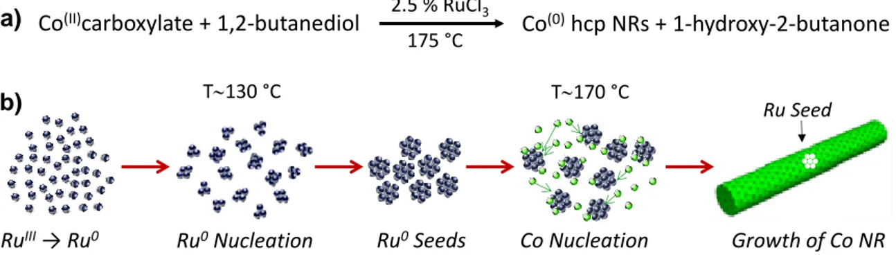
of 1,2-butanediol at 175°C for 30 min under mechanical stirring [8]. Ruthenium chloride (RuCl3.xH2O)
is added to the reacting medium to produce in situ ruthenium seeds for the growth of cobalt, the molar ratio Ru/Co being generally 2.5%. The chemical reaction and the different steps of the nanorod formation are summarized in the figure 1. A typical synthesis of CoNi nanowires is to reduce a mixture of cobalt and nickel acetate in a sodium hydroxide solution of 1,2-propanediol at 175°C under mechanical stirring [9,11]. In this case, ruthenium chloride is also added to produce ruthenium seeds
in situ [11,12]. Cobalt nanowires were also synthesized using cobalt acetate as precursor in solutions
containing sodium hydroxide and stearic acid (C17H35CO2H) in 1,2-propanediol and using ruthenium
seeds [13]. Iridium seeds were also used as nucleating agent by adding small amounts of either H2IrCl6.6H2O in 1,2-propanediol [14] or IrCl3·xH2O in 1,2-butanediol [15]. High temperature
solvothermal syntheses of cobalt nanowires with enhanced magnetic coercivity were carried out in a solution of hexadecylamine in 1,2 butanediol [16]. One of the main interests of the polyol process is its adaptability to large-scale synthesis allowing synthesizing several grams of cobalt in a single batch.
Several syntheses were performed in 1L of 1,2-butanediol using a jacketed reactor. These syntheses allowed preparing between 5 and 10 g/L of Co80Ni20 nanowires [17] and cobalt nanorods [18,19] with
a well-controlled morphology and a very good reproducibility.
Figure 1: Chemical reaction for the synthesis of cobalt nanorods by reduction of a cobalt carboxylate in 1,2-butanediol (a) and scheme of the different steps during the formation of the cobalt rods (b).
2.1.2. Morphology and structure
The mean diameter, dm, and the mean length Lm, of the cobalt rods prepared by the polyol process are
in the range 8-40 nm and 50-400 nm, respectively. The mean aspect ratio ARm = Lm/dm can be varied
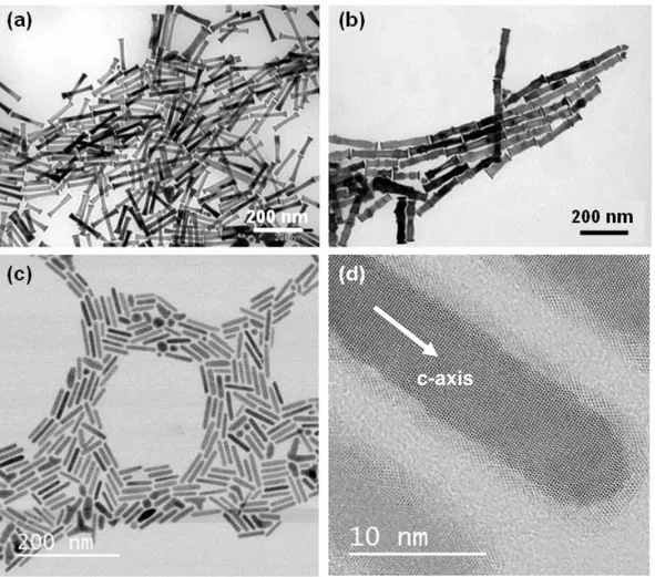
from 3 to 20. The control of the rod morphology is of paramount importance for the control of the magnetization reversal process and their coercivity. Several parameters have been identified to have a strong effect on the rod morphology such as the stirring speed, the basicity of the medium and the nucleating agent. By playing on these parameters it has been possible to modify the rod diameter and the shape of the tips. Representative cobalt rods shown on figures 2a-b illustrate the importance of controlling the stirring speed during the synthesis. Rods with smaller diameter and a smooth surface were obtained at low stirring speed (Fig. 2a) while larger diameter and rough surface were obtained at high stirring speed (Fig. 2b). A mechanism involving the effect of stirring speed on the diffusion rate of the cobalt precursors and the presence of stacking faults was proposed [18].
The cobalt rods prepared by the polyol process with RuCl3.xH2O or IrCl3.xH2O as nucleation agents,
under the standard conditions generally exhibit tips with a larger diameter compared to the main nanorod, like the example shown on figure 2a. This peculiar morphology is detrimental for obtaining high coercivity values (see section 3) and several studies aimed at changing the growth conditions so that large tips are avoided. Gandha et al. performed cobalt reduction in solutions of hexadecylamine in 1,2-butanediol instead of a solution of sodium hydroxide in 1,2-butanediol as reacting medium. The cobalt wires prepared in these conditions exhibited sharp tips that could explain their very interesting magnetic properties [16,20]. The influences of the seeding agent and the heating rate on the cobalt rod morphology were also studied. The mean diameter was found always smaller when anhydrous RuCl3 was used instead of RuCl3.xH2O. With hydrated ruthenium chloride the final mean diameter was
always found in the range 15-30 nm while with anhydrous RuCl3 the diameter was in the range 8-12
nm. By combining this last seeding agent with high heating rate, it was possible to prepare cobalt nanororods with a diameter of 10 nm and an aspect ratio of 5 or higher (Fig. 2c). Interestingly, the tips
RuIII→ Ru0 Ru0Nucleation Ru0Seeds Co Nucleation Growth of Co NR
Ru Seed
T130 °C T170 °C
(a)
(b)
Co(II)carboxylate + 1,2-butanediol Co(0)hcp NRs + 1-hydroxy-2-butanone
175 °C 2.5 % RuCl3
Figure 2. TEM image of Co nanorods prepared in 1 L of 1,2-butanediol (4.7 g of cobalt per batch) using two different stirring speeds (a): 60 rpm (Lm = 120 nm, dm = 17 nm) and (b) 160 rpm (Lm = 190 nm, dm = 28 nm); (c) TEM
image of Co nanorods prepared at 215 °C with a heating rate of 25 °C.min-1 and using anhydrous RuCl
3 as seeding
agent (Lm = 50 nm; dm = 10 nm); (d) HRTEM image of a single crystalline rod in (-2110) zone axis.
The cobalt nanorods crystallize in the hcp structure as inferred from X-ray diffraction. High resolution transmission electron microscopy shows that the c axis of the hcp structure is always parallel to the long axis of the rods (Error! Reference source not found.d). Theoretical calculations showed that the adsorption of the carboxylate ions on the cobalt facets controls the particle growth [21]. The laurate ions have an ambivalent role for the shape control: at moderate concentration their adsorption favors the growth of the {11-20} facets leading to rods, while at high concentration their adsorption favors the (0001) plane leading to platelets. More generally, high concentration of strong bases or carboxylates was shown to be detrimental to the growth along the c axis [8,9]. On the other hand, in neutral medium urchin-like particles are obtained.
2.2. Organometallic chemistry: control of morphology of Co nanorods
2.2.1. General principles
The so called “organometallic method” has taken its name from the early syntheses of nanoparticles using organometallic precursors [22]. It consists in reducing or decomposing organometallic complexes
of low stability under mild reaction conditions. The reactions are performed in an organic solvent and dihydrogen is the most usual reducing agent. During reaction the native ligands are transformed into non-coordinating or weakly coordinating species that have little affinity for the nanoparticle surface. This allows a better control of the nanoparticle surface, by addition of capping agents of choice for the arrest of their growth. A great variety of metal nanoparticles has been synthesized via this method, which gives rise to very well-crystallized nanoparticles even at low reaction temperatures. Furthermore, it yields nanoparticles that are free of native oxides even for easily oxidized metals such as cobalt or iron [23]. This method is also very well-adapted for coordination complexes as precursors, and the use of auxiliary ligands allows controlling of the size and the shape of the nanoparticles. The added ligands play several roles apart from preventing the nanoparticles from coalescing. They also control the size and shape of the nanoparticles by (i) reacting with the precursor, thus forming species with stabilities that differ from the stability of the initial precursor, and (ii) by stabilizing or kinetically blocking the growth of specific crystallographic facets of the growing nanoparticles. Therefore, by affecting the rate and extend of the nucleation and growth steps and the stability of selected types of facets they dictate the size and the shape of the final nanoparticles.
2.2.2. Structure and formation mechanism of cobalt nanorods and nanowires
The first Co nanorods were prepared in anisole at 150°C and under 3 bars of H2, by using the Co(I)
precursor [Co(η3‐C
8H13)(η4‐C8H12)] in the presence of long chain amines and long chain acids [24]. Later,
the precursor [Co(η3‐C
8H13)(η4‐C8H12)] was replaced by the more stable Co(II) silyl amide
{Co[N(SiMe3)2]2THF} [25]. Upon mixing {Co[N(SiMe3)2]2THF} with lauric acid (LA) and hexadecylamine
(HDA), the reaction between them produces a mixture of different compounds with different stabilities towards reduction. The amine rich complexes are very unstable and are the first to be reduced during the nucleation step, giving rise to the seeds on which subsequent reduction of acid-rich compounds of much higher stability are reduced during the growth step. Thus, by modifying the HDA/LA ratio the ratio of the metal reservoir that contributes mainly to the nucleation (amine rich species) versus the reservoir that contributes to the growth (acid-rich species) is modified. The reaction is very sensitive to slight modifications not only of the ratio between the components, but also to the way these components are mixed together during the preparation of the starting solution, that is, before the reaction that gives rise to nanoparticles starts. Reduction of this precursor under H2 at 150°C in anisole
and in the presence of LA and HDA can produce nanoparticles of various morphologies depending of the proportion between Co, LA and HDA [26]. The nanorods are obtained from a solution containing quasi-equimolar amounts of LA and Co and a ratio HDA/Co close to 2 [27]. They have a diameter of about 5 nm and a length that can be tuned between 20 and 100 nm by a choice of the reaction conditions. They are single crystals of hcp structure and the long axis of the rod corresponds to the c axis of the hcp structure (Figure 3).
Figure 3. (a) TEM image cobalt nanorods prepared by the organometallic method; (b) high resolution image of a single rod.
2.2.3. Spontaneous formation of 3D arrays of Co nanorods in solution
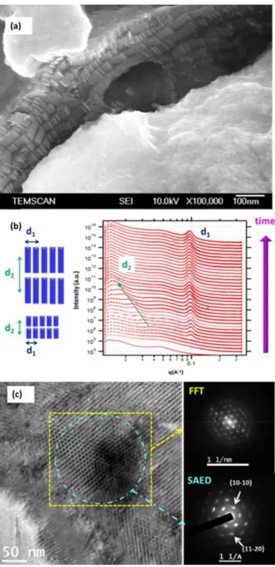
The as-prepared nanorods are included in three-dimensional (3D) superlattices of micrometric lateral dimensions, which are spontaneously formed in solution and they are composed of superimposed (2D) layers of nanorods arranged the one next to the other (Figure 4a). This configuration is similar to a smectic liquid crystal. These supercrystals can be dissolved in toluene. While nanorods are the main reaction product, spherical nanoparticles are always formed simultaneously. A study of the nanorod formation by in situ tandem X-ray absorption spectroscopy (XAS) and small angle X-ray scattering (SAXS) experiments has shown that the 3D organized superlattices are formed directly in solution through a concerted growth−organization process. This means that the nanorods grow inside the superlattices (Figure 4b). Furthermore, the tandem experiments associated to ex-situ monitoring of the growth process by TEM have shown that individual nanorod formation follows a process that involves (i) cobalt nucleation, (ii) a fast atom-by-atom anisotropic growth, and (iii) a slower oriented attachment process that continues well after cobalt reduction is complete. The lateral facets of the nanorods correspond to the {11-20} type facets of the hcp structure as identified by HRTEM of the superlattices at early growth stage. This study has also demonstrated that the superlattices are mesocrystals. That is, the nanorods inside the superlattices possess not only a positional order, but also an orientational order between the individual nanorods) (Figure 4c). While no structuration of the reaction medium has been evidenced we can speculate that a gradual structuration of the reaction medium takes place as the reaction proceeds. The nanorods then probably grow in a matrix that has a different composition of the bulk solution and allows the easy circulation of the active monomers for the atom by atom growth, while at the same time keeps the growing nanorods in close proximity so the oriented attachment is facilitated [28].
Figure 4. (a) SEM image of cobalt nanorods organized in several superimposed 2D layers; (b) In situ SAXS part of the time-dependent spectra of tandem SAXS-XAS experiment for the formation of Co-nanorods: d1 corresponds
to the in-plane centre to centre interrod spacing, and only slightly increases as time passes. The interlamellar spacing d2 starts to be visible just after the in plane interrod spacing d1 and smoothly increases as the time passes;
(c) TEM image and FFT and SAED patterns of the regions indicated with yellow square and cyan circle respectively which show the positional order and common crystallographic orientation of the nanorods respectively.
3.
Optimization of the magnetic properties of individual wires
Magnetic nanorods and nanowires generally exhibit a high coercivity due to their high shape anisotropy. Nevertheless, strong differences can appear depending on the morphology and more particularly on the mean diameter, aspect ratio and shape of the tip. In this section we describe first the results of micromagnetic modelling on individual particles with different morphologies, and we identify the optimal shape for high coercivity. Then, following the lines drawn by the modelling we show how the particle coercivity can be increased by optimizing the chemical process.
3.1. Micromagnetic modelling
Magnetic nanorods and nanowires are systems which are perfectly suited to micromagnetic modelling since these magnetic nanoparticles are dominated by mesoscopic magnetic energies such as the energy of magnetic domain formation, the Zeeman interaction energy with an external field and the demagnetizing field. The objects are also sufficiently small to describe them very accurately with micromagnetic codes operating on nowadays computers.
In order to describe the key geometrical parameters which define the magnetic properties of the Co nanorods, we have used the finite element code Nmag [29] which enables modelling objects with complex geometrical shapes. Other finite element codes such as OOMMF or MuMax are more suitable for thin film systems.
The key input parameters in a micromagnetic model are (i) the geometry of the object, (ii) its magnetization, (iii) the exchange stiffness A and (iv) the magnetic anisotropies. In the case of the Co nanowires discussed in this chapter, the parameters used were Ms = 1400 kA/m, A = 2.8x10⁻¹¹ J/m and
K1 = 4.1x10⁵ J/m3 along the c-axis (wire axis). With these parameters, the exchange length is
nm
M
µ
A
l
ex=
0 s2=
3
.
4
.3.1.1. Effect of the shape of elongated magnetic particles on the coercive field
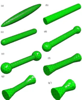
In this section we illustrate how the exact shape of the magnetic nano-objects influences the coercive field. The first step is to model the objects with a mesh. Figure illustrates how real nano-objects can be modelled very precisely. We underline the fact that we make a distinction between ellipsoids, cylinders with flat tips and cylinders with rounded tips.
Figure 5. Different types of particle models and the corresponding meshes. (a) Ellipsoids, (b) cylinders, (c) capped cylinders, (d) dumbbells with small spherical ending, (dumbbell 1), (e) dumbbells with larger spherical endings ending (dumbbell 2), (f) cylinders with small cone endings (diabolo 1), (g) cylinders with larger cone endings (diabolo 2), and (g) small diabolos. (adapted from Ott et al [30]).
Using micromagnetic simulations, it is possible to calculate the hysteresis curves of these various objects. The coercive fields of nano-objects of various shapes and aspect ratios (length/diameter) are summarized on
Figure . To vary the aspect ratio, the length L of the objects is set at 100 nm and the diameter D is varied from 5 to 28 nm. The calculations results raise various comments. In most cases, increasing the aspect ratio beyond 10 barely increases the coercive field. Significant differences are observed between the case of ellipsoidal particles and cylinders. This enables quantifying the limits of the Stoner-Wohlfarth model. In the case of particles with less ideal shapes, a strong loss of coercive field is observed. The coercive field is reduced by about 20% when the shape deviates from the perfect ellipsoidal shape.
µ0 HC
(T)
Figure 6. Variation of the coercivity of Co anisotropic particles as a function of their aspect ratio for different shapes of objects. The magnetic field is applied at at an angle ψ = 5.7° with respect to the object long axis (adapted from Ott et al [30]).
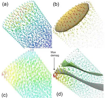
In order to understand where the loss of coercivity stems from it is possible to observe the details of the reversal process. This is presented on Figure . In the case of cylindrical objects, the sharp edges give rise to a “flower” state at the tips of the nanowires (Figure a). The demagnetizing field is rather high but remains much localized at these tips (Figure b). During reversal, the magnetization rotates in a C-shaped form (Figure c) and the demagnetizing field becomes very high at one edge of the cylinder (Figure d). This local increase of the demagnetization field acts as a nucleation point which creates a magnetic domain which propagates along the wire. The coercivity of such an object is thus reduced compared to the case of a perfect ellipsoid.
Figure 7. Magnetic state of a cylinder: (top) at remanence, magnetization and demagnetizing field; (bottom) before reversal, magnetization and demagnetizing field. (a) At remanence, the magnetization is almost perfectly collinear except at the edges of the wire; (b) the demagnetizing field is zero except at these edges. (c) Before reversal, the magnetization rotates at the wire tip in a C-shaped form; (d) the demagnetizing field becomes very high at the edge of the tip (adapted from Ott et al [30]).
The Stoner-Wohlfarth model is quite often referred to when trying to describe the reversal processes in magnetic nanoparticles. Strictly speaking, the Stoner-Wohlfarth model should only be applied when the rotation of the magnetization in the nanoparticle is coherent which can in principle be the case only in ellipsoidal particles in which the demagnetizing field is homogeneous. This behaviour is expected for particles having sizes below a coherent radius defined as Rcoh,sphere= 24lex for spheres and
R
coh,cyl=
3
.
65
l
ex [31] for cylinders. In the case of cobalt, this coherent radius can be calculated tobe in the order of
R
coh,cyl=
7
.
5
nm
which is in the range or above the typical radius of the considered Co nanowires. However, the magnetization reversal proceeds by nucleation at one of the rod tips. Time resolved micromagnetic simulations show that whatever the diameter of the nanowire, the magnetization reversal always proceeds with a transverse domain wall propagation.The details of the reversal process are illustrated on Figure for two diameters, smaller (D=5nm) and larger (D=20nm) than Dcoh. In the case of D = 20nm > Dcoh, the reversal process takes place via a buckling
process (Figure a), the magnetization becomes inhomogeneous along the wire axis. In the case of the small diameter D = 5nm < Dcoh, the reversal does not take place as a fully coherent rotation of the
magnetization [32]. A transverse domain wall is accommodated across the nanowire diameter and the reversal takes place as a transverse domain wall propagation [33,34]. In the other parts of the nanowire, the magnetization remains parallel to the wire which corresponds to a very low energy state. This mechanism which is different from the fully coherent rotation is made possible by the fact that the tips of the wire create nucleation points for domain walls.
Figure 8. (a) Magnetic states close to the coercivity of Co cylinders with different diameters and aspect ratios. The color variation corresponds to the magnetization component along the cylinder axis. The external field is applied with an angle ψ = 5° relative to the cylinder axis. (b) Magnetic reversal in a Co cylinder with D = 20 nm and L = 16D. The color variation corresponds to the magnetization component along the cylinder axis. The reversal proceeds with simultaneous propagation of two domain walls (tail-to-tail and head-to-head) towards the center following nucleation of reversed domains from the left and the right side respectively. The external field is applied with an angle ψ = 5° relative to the cylinder axis (adapted from Pousthomis et al [32]).
3.1.2. Mean diameter and aspect ratio
The coercive field of particles with diameter ranging from 5 to 20 nm and aspect ratios ranging from 1 to 16 has been calculated by micromagnetic simulations. Figure summarizes the results. As a reference, the coercive value expected from the Stoner-Wohlfarth model is plotted in red. As described below, the Stoner-Wohlfarth estimate of the coercive field provides only an upper limit of Hc. In
particles with very small aspect ratio (AR=1-2), the rotation of the magnetization can be considered as
(b)
Wohlfarth model. As soon as the aspect ratio increases, the incoherent rotation of the magnetization is such that the coercive field is reduced with respect to Stoner-Wohlfarth model. It should, however, be noted that for aspect ratios above 8 there is no more gain in Hc. In addition, smaller wire diameters
lead to higher coercive fields.
Figure 9. Coercivity values of Co cylinders with different diameters D as a function of their aspect ratio. The external field was applied at ψ = 22° with respect to the cylinder axis. The prediction of the Stoner-Wohlfarth (SW) model is plotted as a red continuous line (adapted from Pousthomis et al [32]).
3.1.3. Effect of stacking faults
The main structural defects occurring in the cobalt-based nanorods and nanowires are the stacking faults corresponding to a fcc sequence in the hcp stacking. Mercone and co-workers studied the effect of stacking faults on the coercivity of cobalt and cobalt-nickel nanowires by micromagnetic calculations [35]. On figure 10 is reported the coercivity of cobalt rods exhibiting fcc sequences with different thickness at different positions along the wire. A dramatic decrease of the coercivity was predicted when the stacking faults are positioned at the tips whereas the effect is much less important when the stacking faults are in the middle of the wire. These results agree with a nucleation of the magnetization reversal at the tip of the wires.
.
Figure 10. Effect of the stacking faults position on the coercivity values of a Co cylinder (L=100nm and d=10nm) (adapted from Maikha et al [35]).
2 4 6 8 10 12 14 16 0,5 0,6 0,7 0,8 0,9 D= 5 nm D=10 nm D=15 nm D=20 nm Coeri v ity ( Tes la) aspect ratio SW
3.2. Comparison with experimental results
The micromagnetic simulations provided the following general guidelines to produce high coercivity nanowires: (i) the diameter should be as small as possible, (ii) the particles should be single crystals without stacking faults, (iii) the aspect ratio does not need to be higher than 8, (iv) the tips of the wires play a key role and should be as rounded as possible to avoid providing a nucleation point.
For magnetic measurements the nanorods prepared by the organometallic route were purified for the removal of the spherical nanoparticles and were obtained as a powder of about 80% Co content. Magnetic measurements show that they are purely metallic (no exchange bias at 2K showing the absence of surface oxidation). The saturation magnetization Ms is close to the bulk value. The coercivity
increases upon alignment of the nanorods under an external magnetic field and reaches high values,
µ0Hc = 1.0 T at T = 2 K and 620 mT at room temperature (Fig. 11) [36].
Figure 11. (a) TEM image of aligned nanorods prepared by organometallic chemistry; (b) Magnetization curves for non-oriented nanorods evidencing a wide hysteresis with µ0Hc up to 830 mT (⎯) and 490 mT (⎯)
at T=2 and 300 K, respectively, and for oriented nanorods hysteresis with 1.0 T at T=2 K(−• −) and 620 mT at T=300 K (−• −) respectively (adapted from Soulantica et al. [36]).
The cobalt rods prepared by the polyol process were aligned in an external magnetic field and the magnetization loops were measured on aligned assemblies with the external field parallel to the rod long axis. The coercivity in parallel configuration is generally found between 400 and 500 mT at room temperature for rods with a diameter in the range 15-25 nm [32,37]. The presence of stacking faults in long cobalt nanowires and in cobalt-nickel nanowires can explain the fact that in several cases the coercivity did not increase with increasing length [20,32,35]. With rough rods of larger diameter the coercivity decreased to the range of 300-400 mT, in agreement with the micromagnetic calculations. A significant improvement of the coercivity was observed when the mean diameter was decreased to less than 10 nm (Figure 12a) with µ0HC values higher than 720 mT at room temperature. The possibility
to vary independently the mean diameter and the aspect ratio allowed to plot µ0HC as a function of
the rod mean diameter for a given aspect ratio. The micromagnetic calculations were found to be in fairly good agreement with the experimental values (Figure 1b). A further significant improvement of the coercivity was obtained by Gandha et al. with cobalt rods prepared in solvothermal conditions in solution of hexadecylamine in 1,2-butanediol. Coercivity values as high as 1.25 T were measured at room temperature on parallel assemblies of cobalt rods exhibiting a mean diameter d = 15 nm and a
mean length Lm = 200 nm. These exceptional coercivity values are due to the coherent reversal of the
magnetization according to the Stoner-Wohlfarth model [16,20]. The morphology of these rods with sharp tips could explain such high µ0Hc values.
Figure 1. (a) Hysteresis loops of cobalt nanorods prepared by the polyol process. Inset: TEM image of the rods ; (b) Coercivity vs mean diameter of nanorods prepared by the polyol process: (red) calculated for an aspect ratio of 8 (the external field was at an angle ψ =22° with respect to the cylinder axis); (black) measured on aligned nanorods exhibiting an aspect ratio between 6 and 9 (adapted from Pousthomis et al [32]).
4.
2D arrays of Co nanorods combining epitaxy and organometallic
chemistry
The magnetic properties of the nanorods make them good candidates as elementary constituents of an ultra-high-density magnetic recording device. For such an application, an organisation similar to the one obtained directly in solution, in which nanorods forming a 2D layer are immobilized on a support with their long axes perpendicular to the support and organized the one next to the other exposing a surface of tips, could allow addressing the magnetic moment of each nanorod individually, by application of an external stimulus. However, the immobilization of such a monolayer by simple deposition of organized nanorods from the solution does not allow a deposition of one monolayer and is not mechanically robust. For this, a bottom-up method, that allows a direct growth of self-organized hcp cobalt single crystalline nanorods/nanowires on macroscopic crystallographically oriented metallic supports, has been developed.
4.1. Growth and structural characterizations of 2D nanorods arrays
The method is based on the seeded-growth approach, with the support playing the role of the seed. It consists in immersing the support in a solution of a composition similar to the one that in the absence of support gives rise to nanorods, and performing the reaction in the presence of the support. An adaptation of the reaction conditions (reaction temperature/reactant concentration) allows limiting the homogeneous nucleation in solution, allowing the growth to take place epitaxially and selectively on the
2 4 6 8 10 12 14 16 18 20 22 0.2 0.3 0.4 0.5 0.6 0.7 0.8 0.9 experimental modelling µ 0 H C (T ) D m (nm)
(a)
(b)
support. The choice of the crystallographic orientation allows controlling the nanorod growth orientation. A Pt(111) epitaxial film deposited on a sapphire substrate Al2O3(0001) constitutes the
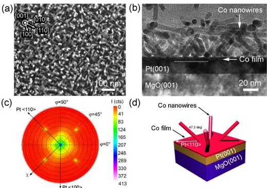
support and gives rise to nanorods that grow perpendicularly. We thus obtain a 2D dense array in which, despite the lack of any pattern on the support, the nanorods/nanowires are perfectly organized in a hexagonal array with densities in the range of 1012 nanowires/cm² (Figure 13). The rod diameters are in
the range of 6-12 nm depending of the synthesis parameters and each nanowire is surrounded with an organic shell, resulting in packing fractions comprised between 38 % and 62 % [38].
Interestingly, Co nanorods/nanowires can be grown epitaxially on substrates of different orientations, and different compositions. Using films exposing 6-fold symmetry surfaces such as Pt(111), Au(111), and Co(0001), the Co growth leads to vertical nanorods/nanowires self-organized in dense and large scale arrays. On films presenting 4-fold symmetry such as Pt(001) and Cu(001), the Co growth leads also to nanorods/nanowires the axis orientations of which are tilted with respect to the normal of the support (Figure 14). Such orientations are dictated by the epitaxial relationships between the growing metal and the support surface [39]. Thus, this approach of solution epitaxial growth combines the advantages of solution chemistry which produces shape-controlled and monodisperse metallic nanocrystals, and of seeded-growth on a crystallographically oriented metallic film that efficiently controls orientation through epitaxy.
Figure 13. 2D arrays of nanorods and nanowires on Pt(111): (a) SEM image of the surface of nanorods grown on the support; (b)TEM of a cross section of an array of nanorods; (c) HRTEM of a cross section. In the insets the corresponding FFT of the framed Co and Pt areas evidencing the epitaxial growth of hcp Co on Pt; (d) SEM image of the surface of nanowires grown on the support; in the inset small angle neutron scattering pattern of the sample, showing the hexagonal arrangement of the Co nanowire array; (e) magnified SEM image of the surface of nanowires; (f) TEM of a cross section of the nanowires on the support (the top Pt layer is added for FIB-assisted TEM sample preparation).
Figure 14. 2D array of tilted nanorods on Pt(001): (a) SEM image of the surface of nanorods grown on Pt(001); Inset: crystalline directions of the Pt(001) film ; (b) Cross-sectional TEM micrograph of the same sample. (c) X(ray diffraction pole figure of the Co{0002} reflections, indicating four satellite spots at χ = 47.3 deg. (d) Schematic 3D view of the Co NR orientations on Pt(001) deduced from c).Reprinted with permission from (39). Copyright (2015) American Chemical Society.
4.2. Magnetic properties of 2D arrays of perpendicular nanorods
As the Co nanorods/nanowires crystallize in the hcp structure with the c axis along the wire axis, the uniaxial hcp magnetocrystalline anisotropy combines with the shape anisotropy to define a perpendicular anisotropy with the easy axis perpendicular to the substrate, i.e. parallel to the nanowires (Figure 15). Due to important dipolar interactions in such dense arrays, the easy axis loops are sheared, as in perpendicular magnetic media, due to the demagnetizing interaction field [40]. Along this direction, coercive fields of 0.35 T and 0.63 T at 300K and 4K respectively are measured for packing fraction of 0.38. Ferromagnetic resonance and magnetic torque measurements have evidenced values of magnetocrystalline anisotropy constants K1 and K2 of more than 40% higher than
Figure 15. Magnetic hysteresis loops of a 2D dense array (P = 0.38) of Co nanowires on Pt(111) for magnetic fields applied perpendicular and parallel to the substrate respectively at (a) 300K and (b) 4K.
5. From nanowires to 3D bulk permanent magnets
The excellent intrinsic properties of Co NRs make them very interesting building blocks for permanent magnets. They exhibit a high saturation magnetization (µ0MS = 1.79 T at room temperature), much
higher than the barium and strontium hexaferrites and slightly higher than the NdFeB alloys. Moreover, elongated single domain nanoparticles such as cobalt nanorods and nanowires exhibit a very high magnetic anisotropy thanks to the addition of shape and magnetocrystalline anisotropy. The figure of merit of a permanent magnet is the energy product - or (BH)max - corresponding to the
maximum energy stored in the magnet[42,43]. To reach a high energy product a magnet must combine a square magnetization loop with both a high remanent magnetization (Mr) and a high coercivity (HC).
In the section 2 the shape optimization of cobalt rods and wires to reach very high coercivity was described. In this section, general considerations on the magnetic properties of 3D assemblies of elongated particles are presented, then the fabrication of parallel assemblies of cobalt nanorods and the assessment of their energy product are described. Finally, consolidations of magnetic nanorods and nanowires to form bulk permanent magnets are reported.
5.1. Magnetic properties of 3D assemblies of nanowires
5.1.1. Influence of the degree of alignment
When considering assemblies of nanowires, the degree of wire alignment is one of the key parameters that influence the magnetic properties. Figure 2a shows the evolution of the hysteresis cycle measured at an angle with respect to the nanowire orientation. When the magnetic field is strictly parallel to the wire axis, a large coercive field together with a high remanence is observed. As soon as the applied field is tilted with respect to the wire axis (e.g. 10°), the coercive fields drops quickly. On the other hand, the remanence remains very high (since it is given by the cosine of the tilt angle). As the magnetic field is further tilted to a direction perpendicular to the wire, the coercive field and the remanence decrease to zero. Figure 16b compares the case of an assembly of randomly oriented nanowires (black curve) and the case of an assembly of aligned nanowires (red and blue curves). In the former case, one obtains an isotropic material with average properties, while in the aligned cases, the properties of the material are improved (Hc and Mr) in the direction of the wires alignment (blue curve), and conversely,
Figure 2 (a) Evolution of the hysteresis loop as calculated in the Stoner-Wohlfarth model for an ellipsoid with an aspect ratio of 3.6 for different orientations of the applied field with respect to the easy axis ; (b) Calculated in-plane hysteresis loops of an isotropic (black) and of an aligned sample (blue easy axis, red hard axis) (adapted from Fang et al [44]).
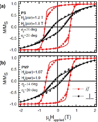
The degree of alignment in a wire assembly can be readily quantified by magnetometry measurements. Figure 3 shows hysteresis cycles measured on aligned nanowires cast in different polymer matrices (PS and PVP) and measured along the hard and easy axis. Quantitative information about the degree of alignment can be readily obtained from the remanence values Mr/Ms measured along the easy and
hard axis. The measurements of Figure 3 were modelled within the Stoner-Wohlfarth model assuming angular Gaussian distribution of width and of the wires orientation in the plane of the film and
perpendicular to the film. From this modelling the width of angular distribution could be estimated to be around 20°.
Figure 3. Hysteresis loops at room temperature of cobalt nanowires dispersed and aligned in (a) polystyrene (PS
(b)
(a)
(b)
(a)
5.1.2. Effect of dipolar interactions
In dense assemblies, the magnetic wires are very close to each other and direct local dipolar interactions between wires can be important. Figure represents the dipolar stray field at the tip of a nanowire (L=100 nm, r=5 nm, µ0Ms = 1T) calculated using Finite Element Method Magnetics (FEMM)
[45]. It illustrates that the dipolar stray fields are very localized around the tip (in a volume with a typical size given by the radius of the nanowire). The stray fields are on the order of 0.1 T at a distance of 4 to 7 nm from the nanowire tip (Figure b). Thus, for nanowires separated by distances that can be as small as 2 to 4 nm, the dipolar field radiated by one wire on its neighbours can still be on the order of a fraction of one tesla. These direct dipolar interactions lead to changes in the magnetization processes. In particular, for aligned wires, they will lead to an effective tendency to anti-ferromagnetic coupling and thus to a decrease of the remanent magnetization and a reduction of the coercive field.
Figure 18. Dipolar field outside the tip of a magnetic nanowire (L=100 nm, r=5 nm, µ0Ms=1 T) (gray bar) calculated
using FEMM [45]. (a) Axial mapping of the induction outside the wire. (b) Magnitude of the induction along the wire axis and the radial axis. The dipolar stray fields drop quickly but are still on the order of 0.1 T at a distance of 4 to 7 nm from the wire edges.
It is possible to quantify the magnitude of these dipolar interactions via Henkel plots (M plots) or
FORC plots. In order to construct the M plots, the IRM (Isothermal Remanent Magnetization) IR(H)
and the DCD (Direct Current Demagnetization) ID(H) curves are measured [46]. M plots are calculated
by the relation:
( )
( )
1 2 − − = I H I H M R D For non-interacting particles, M=0. Positive (respectively negative) M are interpreted as
ferromagnetic (respectively antiferromagnetic) inter-particles interactions. The case of aggregates of nanowires is illustrated on Figure . The Henkel plot shows negative M values which suggests that the
local interactions between neighbouring wires are anti-ferromagnetic. The observed M values are
however fairly small (0.05 to 0.2) which correspond to limited dipolar interactions. In order to get a more detailed insight of the nanowires interactions, FORC plots may be used [47].
Figure 19. (a) TEM images of Co wires deposited under an aligning magnetic field. (b) Construction of the M plot by the IRM and DCD data for a sample dispersed in a PVP matrix (adapted from Panagiotopoulos et al [46]).
5.1.3. Influence of the packing density
Micromagnetic calculations were performed on aggregates of nanowires with various packing densities [48,49]. From the simulated hysteresis cycles, it is possible to estimate the maximum BHmax
value which can be achieved even in the presence of dipolar interactions. Figure shows the variation of the energy product of nanowire-based materials in the case of cobalt and iron nanowires. In the case of Fe, there is an optimal packing density above which the energy density decreases. This is due to the fact that above a certain density, the dipolar interactions become very high, leading to a loss of coercivity due to the iron very small magneto-crystalline anisotropy. In the case of cobalt, a high packing fraction is not detrimental because of the large magneto-crystalline anisotropy, thus the BHmax
increases as a function of the packing density, reaching values as large as 450 kJ/m3 for a close packed
structure. Such high values are identical to sintered NdFeB magnets. However, such close packed structures cannot be achieved because of a small degree of misalignment and the presence of surfactant and oxide on the surface of the magnetic wires.
Figure 20. Energy product (BH)max as a function of packing fraction for cobalt (red diamonds) and iron (black
circles) nanowires. The continuous lines show the calculations under the assumption of square loops. (adapted from Panagiotopoulos et al. [48]).
(b)
(a)
5.2. Dense arrays of parallel nanorods
Cobalt nanorods synthesized in 1,2-butanediol were washed several times with alcohol and toluene and separated from the washing solvents by centrifugation. The nanowires were then dispersed again in chloroform which appeared to be the best solvent for the nanorods. In chloroform, the nanorod suspensions can remain stable for hours. The particle suspensions in chloroform we poured in molds (Teflon or aluminum) and dry casted under a magnetic field generated by an electro-magnet (Figure 21a). Note that this field should be extremely homogeneous with low gradients. Not fulfilling this condition will result in an inhomogeneous sample, since the wires will migrate to the extremities of the film during the casting. In order to minimize these gradients, we used NMR or EPR/FMR grade electromagnets with very large polar pieces (200 mm in diameter). Casting under a magnetic field induces an alignment of the wires (Figure a), inducing in turn an intrinsic bulk magnetic anisotropy in the sample. The applied field should be on the order of a fraction of a tesla to induce a proper alignment of the wires. Example of wafers made up of dense assembly of cobalt nanorods are given Figures 21b,c. Despite the absence of bonding the resulting assemblies are quite stiff.
Figure 21. (a) The wires are aligned between the polar pieces of an electromagnet. The aligning magnetic field Halign can go up to 1T. (b) and (c) Wafer of aligned nanowires after drying under magnetic field (adapted from
Anagnostopoulou et al. [37]).
The nanorod assemblies were characterized by scanning electron microscopy (SEM), small angle neutron scattering (SANS) and magnetometry to assess the quality of the alignment. Figure a,b show electron microscopy images of dense assemblies of cobalt nanorods with two different mean diameters. In both cases the long-axis orientation distribution is narrow. Scanning electron microscopy only provides information on the surface of the sample. Small angle neutron scattering is able to probe the whole volume of the sample and provides average information on the order of the wires within the sample. Figure 22c shows a representative SANS pattern of a cobalt rod assembly with the neutron beam direction perpendicular to the rods long axis. Their good alignment is revealed by a strong contrast between the scattering intensity parallel and perpendicular to the rods (Figure 22c). To a first approximation, the mean axis-to-axis distance, Dm, between adjacent rods can be deduced from the q
value at the maximum of the scattering intensity perpendicular to the rods according to q⊥,max = 2/Dm.
Thus, the mean spacing between the rods can be estimated as Dm-dm, with dm the mean diameter
inferred from the transmission electron microscopy images. In the example presented on figure 22d
the mean diameter measured by SEM was dm = 17.5 nm and mean distance inferred from SANS was
Dm = 21.2 nm, indicating a mean inter-rod distance of 3.8 nm. The spacing between the rods is occupied
by the carboxylate ligands grafted to the rod surface.
Figure 22. SEM micrographs of the pellets showing the Co NRs alignments (a) mean diameter dm = 20 nm; (b)
mean diameter dm = 28 nm ; (c) SANS pattern of aligned 17.5 nm nanowires with a strong contrast between the
scattering intensities perpendicular and parallel to the alignment ; (d) SANS profile perpendicular and parallel to the wires. The correlation peak at the position q⊥= 0.295 nm-1 provide information on the orientation order of the nanowires as well as their mean spacing.
The degree of alignment in a wire assembly can be readily assessed by the squareness of the M(H) loop, measured with the applied field parallel to the easy axis. The squareness, SQ, can be defined by the ratio: S C
M
H
A
SQ
=
(Eq. 1)with A the area below the M(H) loops in the second quadrant area, i.e. from H = 0 to H = -Hc, and
HCMS corresponding to the area of the ideal rectangle loop obtained for a fully parallel configuration
(see Figure 16a). Different M(H) loops with different squareness are shown on figure 23a. The optimal shape of the hysteresis curve for a permanent magnet is a square one in which the coercivity is at least half of the remanent polarization of the material.
volume fraction is lower than the rod volume fraction [50]. Actually, the rod assemblies contain three components, the cobalt core, the cobalt oxide shell and the remaining organic molecules (ligands). The volume fraction of each component was determined combining magnetometry and thermal analysis [37]. These two techniques allowed to determine first the weight fraction of each component. The saturation magnetization of the dense rod assemblies was generally found in the range 120 and 125 emu.g-1. These values correspond to a mass fraction of ferromagnetic cobalt in the range 74-77%,
considering 160 emu.g-1 for the saturation magnetization of bulk Co. The thermal analyses were then
performed. A mass m of sample was first heated in air up to 700°C in order to remove all the organics and to fully oxidize the cobalt core. This treatment was followed by a reduction of the cobalt oxide in metal cobalt at 700°C under a mixture of H2/Ar. The total mass variation of the two steps m gives the
total mass fraction of cobalt, i.e. cobalt involved in the metal core and the cobalt oxide shell. Assuming that the cobalt oxide is CoO as previously identified [50], it then possible to calculate the weight fraction cobalt oxide and by deduction of ligands. The volume fraction was then calculated assuming that that the density of Co, CoO and ligands are similar to the bulk values, 8.9, 6.4 and 0.9 g.cm-3,
respectively. In most of the dense assemblies dried under a magnetic field of 1T the magnetic volume fraction was found in the range of 45-55 % depending on the drying procedure and on the homogeneity of the rod morphology. For a rod mean diameter of about 20 nm such a magnetic volume fraction corresponds to a cobalt oxide shell thickness in the range of 1-1.5 nm and a inter-rod distance in the range of 3-4 nm, in good agreement with the SANS measurements.
The determination of the magnetic volume fraction (VM) in the nanorods assemblies allowed plotting
the B(H) loops and to assess the BHmax. On Figure 23b are plotted the second quadrant of the B(H)
loops of three rod assemblies, with almost the same magnetic volume fraction (48.8%), but whose magnetization loops did not exhibit the same squareness. The comparison of these three samples showed that the BHmax increased from 51 to 125 kJ.m-3 when SQ increased from 0.57 to 0.93. On figure
23c are plotted the second quadrant of the B(H) loops of two rod assemblies the magnetization loops of which exhibited almost the same squareness (0.93 and 0.96) but with different magnetic volume fraction. The values of BHmax increased from 125 to 165 kJ.m-3 when the magnetic volume fraction
increased from 48.8% to 54.4 %.
High volume fraction combined with a nearly perfect alignment allowed to reach (BH)max values higher
than the energy product of permanent magnets based on barium hexaferrite or AlNiCo magnets [51]. In order to increase the BHmax the next goal is to increase the magnetic volume fraction in the rod
assemblies. On figure 23d are compared the expected values of BHmax for ideal hexagonal arrays of
nanorods as a function of the rod diameter for oxidized and non-oxidized nanorods with an inter-rod distance of 3.5 nm, and for non-oxidized nanorods with an inter-rod distance fixed of 2 nm. For a given diameter the BHmax increases significantly, when the volume fraction increases, by avoiding either the
cobalt oxide shell and/or by decreasing the average distance between the rods. For assemblies of rods of diameter d = 15 nm, for which very high coercivity has been already reported [16], the BHmax could
Figure 23. (a) Normalized M(H) loops of cobalt nanorod assemblies exhibiting different squareness SQ (all the
assemblies exhibited a needle shape, the applied field was parallel to the rods and to the long axis of the macroscopic needle); (b) Second quadrant of the B(H) loops calculated with the corresponding magnetic volume fraction (VM) in the arrays, blue triangles: VM = 48.7 %, SQ = 0.93, black open circles: VM = 48.7 %, SQ = 0.74, red
diamonds: VM = 48.8 %, SQ = 0.57. The similar magnetic volume fraction in this three samples allows assessing
the influence of the squareness of the M(H) loop on the energy product BHmax; (c) Influence of the magnetic
volume fraction on the BHmax value comparing two cobalt rods assemblies with almost the same squareness (SQ
= 0.93) and two different volume fraction blue triangles: VM = 48.7 %, magenta squares VM = 54.4 % ; (d)
Theoretical energy product of hexagonal arrays of perfectly aligned cobalt nanorods as a function of their mean diameter d in three different cases : oxidized rods with a CoO shell thickness of 1.2 nm separated by a ligand shell of 3.5 nm (full square), non-oxidized rods separated by a ligand shell of 3.5 nm (open circle), non-oxidized rods separated by a ligand shell of 2 nm (full triangle) (adapted from Anagnostopoulou et al. [37]).
5.3. Consolidation of nanowires
Several studies reported the fabrication bulk 3D magnets by compaction of magnetic nanorods or nanowires using Spark Plasma Sintering (SPS), cold (CC) or hot compaction (HC). The compaction step is required to improve the mechanical strength and to increase the magnetic volume fraction by decreasing the distance between the particles (see above). Nevertheless, the compaction step must not degrade the anisotropic shape and the small particle diameter. Indeed, high coercivity in the consolidated materials can be obtained only when the magnetization reversal proceeds via individual reversal in each nanorod. The consolidation experiments must be mild enough to preserve the rod morphology in the compacted materials. In particular, the temperature must be limited, since it was established that raw cobalt nanorods undergo sintering and oxidation when they are heated at a temperature higher than 200°C [52]. Consolidation at high pressures involved in the cold and hot
-800 -400 0 400 800 -1,0 -0,5 0,0 0,5 1,0 M/M s H / kA.m-1 SQ= 0.93 SQ= 0.74 SQ = 0.57 (a) -400 -300 -200 -100 0 0,0 0,2 0,4 0,6 0,8 1,0 (b) B / T H / kA.m-1 SQ= 0.93 SQ= 0.74 SQ= 0.57 BHmax: 125 kJ.m-3 82 kJ.m-3 51 kJ.m-3 -400 -350 -300 -250 -200 -150 -100 -50 0 0,0 0,2 0,4 0,6 0,8 1,0 (c) B / T H / kA.m-1 Vf= 48 % Vf= 54 % BHmax: 165 kJ.m-3 125 kJ.m-3 5 10 15 20 25 30 35 0 50 100 150 200 250 300 350 400 450 (b) (B H) ma x / kJ .m -3 d / nm (d)
The first consolidations of magnetic nanowires were reported by Ouar et al.. Bulk magnets were obtained by spark plasma sintering of Co80Ni20 nanowires [17,53]. The final sintering temperature was
set at 100 °C and a pressure of 100 MPa was applied [53]. High coercivity was obtained in the final material (> 400 mT) which is a very interesting result since this value was more than twice the value of the initial particles [17]. Nevertheless, the remanence-to-saturation values was only 0.53, even if the consolidations were done under an external magnetic field of 1T. The presence of CoNi particles with urchin-like shape in the powder before consolidation could prevent from a good alignment in the final compacted materials.
In order to improve the thermal stability and to avoid the sintering during the compaction at high pressure, surface-modified cobalt rods were synthesized. It was observed for example, that the Co NRs encapsulation with a thin carbon layer via treatment in organic solvents enhanced their thermal stability [54]. For compaction at high pressures, a thin layer of CoSb alloy was grown at the surface of cobalt nanorods by reduction of Sb acetate dispersed in a solution consisting of 1,2-tetradecanediol in oleylamine [55]. Figure 24 shows an example of a magnet prepared by compaction of core-shell Co@CoSb nanorods. Two methods were compared, cold compaction under 1.5 GPa and hot compaction at 180 °C under a pressure of 150 MPa with an external magnetic field of 1.7 T. In both cases the coercivity of the Co@CoSb rods was preserved after compaction showing that the thin non-magnetic shell of CoSb at the surface of the rod prevented the rod sintering. The cold-pressed sample exhibited the highest packing density (56%) whereas the best Mr/Ms ratio was obtained with the hot compaction in presence of the external magnetic field. Nevertheless, the remanence was limited to 60 % showing the difficulty to align the rods from the powder. The energy product of the hot-compacted sample was equal to 10 kJ·m−3. This value is lower than the energy product of aligned nanorods. An
improvement in this value would require a better alignment of the Co@CoSb rods to increase the Mr/Ms and the squareness of the magnetization curve [55].
Figure 24. Images of bulk magnets prepared by consolidation of (a) Co@CoSb nanorods ; (b) Co nanorods
The issue of misalignment in the compacted materials was partially addressed by consolidations of pre-aligned cobalt rods pellets like those shown on Figure 25a. Hot compaction at 180 °C under different pressures and cold compaction were performed on rods with diameters of c.a. 11 and 28 nm [19]. In the table 1 the magnetic properties and the consolidation conditions of two magnets prepared with cobalt rods are summarized. The remanence to saturation ratio on the M(H) loops of the compacted materials were found in the range 73 - 82 %, significantly higher than the previous values
0.5 cm 0.5 cm
obtained on after compaction of random powders (Figure 25e). The highest Mr/Ms value of 82 % was obtained for the 1 GPa cold compacted 11 nm rods, showing a fairly good alignment. The magnetic volume fraction in the magnets were calculated as the ratio between the saturation magnetization of the magnet and that of bulk cobalt. Much higher volume fraction was obtained with the rods of larger diameter (Tab. 1). The mean axis-to-axis distance, Dm, between the rods in the compacted materials
was measured by SANS (Figures 25b-d). From these values the mean spacing between the rods was deduced by subtracting the mean diameter, Dm - dm. It was found between 1.7 and 1.9 nm (Tab. 1),
showing that in both cases the compaction was effective in reducing the spacing between the rods. The densities of the magnets were measured by pycnometry and were found equal to 7.1 and 5.0 g.cm -3for the rods of diameter 28 and 11 nm, respectively (Tab. 1). These values correspond to respectively
80 and 56 % the density of bulk metal. The low magnetic fractions deduced from magnetometry shows that the cobalt rods were partially oxidized. Models of dense materials with cobalt rods exhibiting a surface oxide shell of 1.2 nm explained well the density and magnetic volume fraction values [19]. The energy product was found to be higher in the magnet prepared with the thicker rods because of the higher magnetic volume fraction, but the highest coercivity was found for the magnet prepared with the thinner rods, in agreement with the modeling described in the section 2. Energy products as high as 65 kJ.m-3were obtained by the consolidation of cobalt nanorods, a value higher than the energy
product of the hexaferrite based magnets and competing with most of anisotropic cast Alnico grades commercially available [56]. Significant improvements could be obtained by increasing the magnetic volume fraction if the rod oxidation is avoided [19,37].
Magnet I II
Diameter cobalt rods 11 nm 28 nm
Consolidation Room temperature – 1 GPa 180 °C – 450 MPa
Mr/Ms (%) 82 73
µ0Mr (T) 0.5 0.82
VM (%) 34.5 64
Density (g.cm-3) 5.0 7.1
Mean spacing (SANS) 1.9 nm 1.7 nm
HC (kA.m-1) 334 224
BHmax (kJ.m-3) 31 65
Table 1. Experimental compaction conditions and magnetic properties of two magnets prepared with cobalt nanorods.
Figure 25. (a) Image of pellets of pre-aligned cobalt nanorods before compaction ; (b) SANS pattern of 10.9 nm
nanorods cold compacted at 1 GPa ; (c) SANS pattern of 28.3 nm nanorods hot compacted at 450 MPa ; (d) Structure factor S(q) = I(q)×q², with I(q) the intensity scattered perpendicular to the rods, of four magnets prepared with rods with two different mean diameter (dm = 10.9 and 28.3 nm) using hot compaction (H.C.) or
cold compaction (C.C.) procedures in different conditions ; (e) second quadrant of the M(H) loops of the four magnets.
6.
Conclusion
Liquid phase chemical syntheses permit to produce cobalt nanowires and nanorods growing along the c axis of the hcp structure. In the polyol method the selective adsorption of long-chain carboxylate ions on the {11-20} open facets is the driving force of the anisotropic growth. In the organometallic chemistry method, a combination of long-chain carboxylate ions adsorption on the {11-20} facets and supramolecular organizations that act as a template for the oriented coalescence of short nanorods are responsible for the growth of 3D mesocrystals of nanorods. Due to their structural properties and very high crystalline quality the cobalt rods and wires prepared by the chemical methods exhibit very
high magnetic anisotropy thanks to the addition of the shape and the magnetocrystalline anisotropies. These nano-objects are also model systems for studying the magnetism of anisotropic objects as well as the interactions between magnetic nano-particles. Their excellent properties in terms of magnetization (Ms 1.7T) and coercivity (µ0HC = 0.3-1T) make them candidates for the fabrication of
permanent magnets and for applications in the field of magnetic recording or magnetic sensors. Densely packed 2D hexagonal arrays of cobalt nanowires were directly grown on platinum substrates grown combining solution chemistry with epitaxial growth. 3D assemblies of parallel cobalt nanorods were obtained by alignment under magnetic field of cobalt rods prepared by the polyol method and consolidation experiments were successful in producing bulk magnets. High energy products were measured: higher than 150 kJ.m-3 and up to 65 kJ.m-3 at small and large scale, respectively. This
proof-of-concept shows that permanent magnets with performances which fill the gap between hexaferrite and rare-earth based magnets, can be prepared by a bottom-up approach from particles combining shape anisotropy and magnetocrystalline anisotropy. Thus, a new class of rare-earth free permanent magnets was obtained. During the last few years significant improvements were obtained concerning the coercivity of cobalt rods via shape optimization. Further improvements on the 3D consolidated materials are expected by increasing the magnetic volume fraction through both improving the parallel order after compaction and avoiding the cobalt surface oxidation during the process.
A possible outlook for the magnetic rods synthesized by the chemical methods is that it is possible to make more complex the objects by adding new functionalities. Starting from these nanowires, it is possible to produce core-shell particles. It is for example possible coat them with a noble metal affording optical properties, in order to design magneto-optical objects with specific properties. It is also possible to functionalize the particles to target tumour cells in the body and mechanically destroy them by inducing a movement of the nanowires by low frequency alternating magnetic fields. Their particular magneto- rheological behaviour could also make interesting for bio-sensors [57,58].
References
1 F. Fiévet, S. Ammar-Merah, R. Brayner, F. Chau, M. Giraud, F. Mammeri, J. Peron, J.-Y. Piquemal, L. Sicard, G.
Viau, The polyol process: a unique method for easy access to metal nanoparticles with tailored sizes, shapes and compositions. Chem. Soc. Rev., 2018, 47, 5187-5233.
2 F. Fiévet, J.-P. Lagier, M. Figlarz, M.R.S. Bull. 14, 29 (1989) ; F. Fiévet, J.-P. Lagier, B. Blin, B. Beaudouin, M.
Figlarz, Solid State Ionics 32/33, 198 (1989).
3 G. Viau, F. Fiévet-Vincent and F. Fiévet, Solid State Ionics, 84, 259 (1996).
4 D. Kodama, K. Shinoda, K. Sato, Y. Konno, R. J. Joseyphus, K. Motomiya, H. Takahashi, T. Matsumoto, Y. Sato,
K. Tohji, B. Jeyadevan, Adv. Mater. 18, 3154 (2006).
5 Ph. Toneguzzo, G. Viau, F. Guillet, E. Brunetton, O. Acher, F. Fiévet-Vincent and F. Fiévet, J. Mat. Sci., 35, 3767

![Figure 10. Effect of the stacking faults position on the coercivity values of a Co cylinder (L=100nm and d=10nm) (adapted from Maikha et al [35])](https://thumb-eu.123doks.com/thumbv2/123doknet/12698935.355494/13.892.229.664.778.1089/figure-effect-stacking-position-coercivity-cylinder-adapted-maikha.webp)