HAL Id: cea-02500835
https://hal-cea.archives-ouvertes.fr/cea-02500835
Submitted on 6 Mar 2020
HAL is a multi-disciplinary open access archive for the deposit and dissemination of sci-entific research documents, whether they are pub-lished or not. The documents may come from teaching and research institutions in France or abroad, or from public or private research centers.
L’archive ouverte pluridisciplinaire HAL, est destinée au dépôt et à la diffusion de documents scientifiques de niveau recherche, publiés ou non, émanant des établissements d’enseignement et de recherche français ou étrangers, des laboratoires publics ou privés.
2D simulations of hydride blister cracking during a RIA
transient with the fuel code ALCYONE
J. Sercombe, T. Helfer, E. Federici, D. Leboulch, T. Le Jolu, A. Hellouin de
Menibus, C. Bernaudat
To cite this version:
J. Sercombe, T. Helfer, E. Federici, D. Leboulch, T. Le Jolu, et al.. 2D simulations of hydride blister cracking during a RIA transient with the fuel code ALCYONE. Top Fuel 2015, Sep 2015, Zurich, Switzerland. �cea-02500835�
1
2D SIMULATION OF HYDRIDE BLISTER CRACKING DURING A RIA
TRANSIENT WITH THE FUEL CODE ALCYONE
J. SERCOMBE, T. HELFER, E. FEDERICI,
CEA, DEN, DEC
F-13108 Saint-Paul-lez-Durance, France.
D. LEBOULCH, T. LE JOLU, A. HELLOUIN DE MENIBUS
CEA, DEN, DMN, F-91191 Gif-sur-Yvette, France.
C. BERNAUDAT
EDF, SEPTEN,
69628 Villeurbanne Cedex, France.
ABSTRACT
This paper presents 2D generalized plain strain simulations of the thermo-mechanical response of a pellet fragment and overlying cladding during a RIA transient. A fictitious hydride blister of increasing depth (25 to 90% of the clad thickness) is introduced at the beginning of the calculation. When a pre-determined hoop stress is exceeded at the clad outer surface, radial cracking of the blister is taken into account in the simulation by a modification of the mechanical boundary conditions. The hoop stress criterion is based on Finite Element simulations of laboratory hoop tensile tests performed on highly irradiated samples with a through-wall hydride blister. The response of the remaining clad ligament (beneath the cracked blister) to the pellet thermal expansion is then studied. The simulations show that plastic strains localize in a band orientated at ~ 45° to the radial direction, starting from the blister crack tip and ending at the clad inner wall. This result is in good agreement with the ductile shear failures of the clad ligaments observed post RIA transients. Based on a local plastic strain failure criterion in the shear band, ALCYONE simulations are then used to define the enthalpy at failure in function of the blister depth.
1. Introduction
The behavior of high burnup fuel during a Reactivity Initiated Accident (RIA) has been studied experimentally in the NSRR [1][2] and CABRI reactors [3][4]. It is now well established that the accumulation of hydrides beneath the thick outer zirconia layer that can form in zircaloy-4 claddings during base irradiation is a key factor with respect to fuel rod failure during the Pellet Cladding Mechanical Interaction (PCMI) phase of a RIA [5]. In the extreme case of outer zirconia spalling, the local cold spot that appears triggers hydrogen diffusion in the cladding resulting in a massive hydride precipitation and eventually to a hydride blister (or lense).
Many experimental works have shown that precipitated hydrides result in a loss of ductility of zirconium alloys, especially at low temperatures. In the extreme case of a through-wall hydride blister, the failure can be brittle with no residual strains [6]. During simulated RIA transients on zircaloy claddings, it has been reported that the rod failure proceeds in a mixed mode with a brittle fracture of the heavily hydrided periphery of the cladding and a ductile propagation in the remaining clad ligament [1-4]. Ductility is here associated to the change of direction of the through wall crack, radially orientated in the hydride rim or blister and then bifurcating at ~45° untill the clad inner wall.
In this paper, the failure of a fuel rod containing a fictitious hydride blister of varying thickness during a simulated RIA transient is studied with the 2D generalized plain strain scheme of the fuel code ALCYONE. The relationship between the blister depth and the
2 maximum fuel enthalpy is seeked by multiple simulations of the CABRI REP-Na8 test [1-2].
2. The 2D model of the fuel code ALCYONE
ALCYONE is a multi-dimensional fuel code co-developed by the CEA, EDF and AREVA within the PLEIADES environment which consists of three different schemes [7]: a 1.5D scheme to model the complete fuel rod, a 3D scheme to model the behaviour of a pellet fragment with the overlying cladding, a 2D(r,) scheme to model the mid-pellet plane of a pellet fragment, see Figure 1. The different schemes use the same Finite Element (FE) code CAST3M [8] to solve the thermo-mechanical problem and share the same physical material models at each node or integration points of the FE mesh. A detailed description of the main models and material parameters considered in the thermo-mechanical code ALCYONE can be found in [9] and [10].
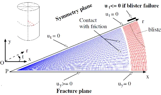
Figure 1 : Mesh and mechanical boundary conditions in the 2D scheme of ALCYONE.
Post-irradiation examinations performed on Pressurized Water Reactors (PWR) pellets after 2 to 5 cycles of base irradiation show that the pellets are usually broken in ~6-10 pieces of irregular size [9]. In the 2D simulation, the behavior of an average fragment representing one eighth of the pellet is studied. Because of the geometrical symmetries, only one sixteenth of the pellet and of the overlying piece of cladding is meshed. The mechanical boundary conditions considered in the 2D calculations are shown in Figure 1. The opening and closing of the radial cracks between the pellet fragments is allowed by applying a unilateral condition (uy ≥ 0) on the nodes of the (0x) line. At the pellet-cladding
interface, unilateral contact is assessed and a Coulomb model is introduced to simulate friction-slip or adherence.
The fictitious blister crack is introduced by modifying the boundary conditions on the axis of symmetry of the pellet fragment (0r). Initially, the tangential displacement ut of the
nodes is set to zero. When the hoop stress on the external clad wall reaches a pre-defined threshold, the boundary condition on the nodes included in the depth of the hydride blister is modified. A unilateral condition is applied to avoid non-physical interpenetration with the symmetric part of the blister (ut ≤ 0). Note that this simplified
approach implies that blister cracking has an infinite length in the axial direction (that of the rod axis of symmetry).
3
3. Material properties for the cladding and the hydride blister
To model the behavior of fresh and irradiated Zircaloy-4, the constitutive law developed in [11] is used in ALCYONE. It consists in a unified viscoplastic formulation with no stress threshold between the elastic and viscoplastic regimes. The texture-induced plastic anisotropy of Zircaloy-4 is described by a Hill’s quadratic criterion. The model includes four parameters (strain rate sensitivity exponent, strength coefficient, strain hardening coefficient, Hill’s coefficients) that have been adjusted on an extensive database of laboratory test results (axial tensile tests, hoop tensile tests, closed-end internal pressurization tests) essentially obtained from the PROMETRA program, dedicated to the study of zirconium alloys under RIA loading conditions [12]. The model is able to account precisely for the impact of temperature, strain rate, and irradiation damage on the ultimate stress, on the strain hardening exponent (up to uniform elongation) and on the plastic anisotropy of the material.
The explicit modeling of a hydride blister is a complex problem which would require the realistic modeling of outer zirconia formation and the partial spalling of the layer, the thermo-diffusion of hydrogen and the volume expansion associated with the precipitation of δ-hydrides [13]. Such a work is far beyond the goal of this paper. In the simulations, we assume that a stable and non evolving hydride blister is present at the beginning of a RIA pulse test. The thermo-mechanical behavior of the hydride blister is considered similar to that of the Zircaloy-4 cladding (elastic and viscoplastic). In this respect, it is implicitly assumed that irradiation creep of Zircaloy-4 during base irradiation is sufficient to relax internal stresses generated by the precipitation of δ-hydrides.
The only specific parameter required in the 2D simulations is the stress to failure of the hydride blister. An approximate value of ~145 MPa was deduced by Desquines et al. [6] from a hoop tensile test performed on an irradiated highly corroded clad sample containing a through-wall hydride blister (PROMETRA test 2468, Zircaloy-4, strain rate 5/s, temperature 480°C). The failure of the sample actually took place outside of the gage section. Interpretation of hoop tensile tests is however complex due to structural effects that occur during the experiment (bending, friction. . .). A detailed Finite Element analysis where the clad section and the half cylinder inserts are considered can nevertheless provide realistic estimate of the plastic strains [11][14]. The simulation of the test 2468 has therefore been undertaken and shows that the stress state is far from being homogeneous in the clad thickness and width and depends greatly on the exact position of the blister. With a friction coefficient of 0.1, the hoop stress on the clad outer wall at failure and out of the gage section varies between 150 and 250 MPa.
Figure 2 : Hoop stresses calculated at failure time during the PROMETRA test 2468 (left: friction coefficient 0.1, right: friction coefficient 0.4).
Blister position
Hoop stress (MPa)inserts
4
4. Simulation of the CABRI REP-Na8 test
The CABRI REP-Na8 test was performed on a highly corroded UO2/Zircaloy-4 fuel rod
(maximum corrosion thickness 84-126 µm) with partial spalling detected before the test. The main characteristics of the test are recalled in Table 1 (from [3]).
Fuel Cladding Max. burnup Energy (cal/g) Width (ms) Blister cracking* Loss of tightness* Max. enthalpy UO2 Zy4 60 GWd/t 110.7 75 44 cal/g 78 cal/g 98 cal/g
Table 1: Main characteristics of the CABRI REP-Na8 test (* Enthalpy).
The REP-Na8 test led to the loss of tightness of the rod at an enthalpy of 78 cal/g. Several microphones (or acoustic) signals were however recorded before the gas ejection in the coolant. At an enthalpy level of 44 cal/g, a microphone event located near the Peak Power Node (PPN) has been correlated to a limited axial crack extension inside a hydride blister (depth ~50% of the clad wall thickness), suggesting a possible failure initiation without loss of tightness [3][4]. A preliminary 2D simulation of the base irradiation prior to the REP-Na8 pulse test was first performed with ALCYONE. Note that the same physical and material models are used for base irradiation and RIA calculations. There is therefore no specific initialization of the variables prior to pulse simulations (fragment relocation, intragranular or intergranular gas bubbles, pellet cracking, …). In particular, the pulse t0
pellet clad gap is close to 2 µm and is therefore not artificially closed as it is the case in most of the transient fuel performance codes.
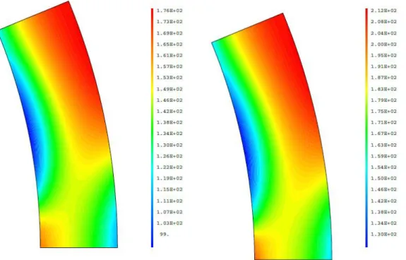
The REP-Na8 pulse test was then simulated with ALCYONE. The hoop stress distribution in the cladding calculated 5 ms before and at the time of the microphone event related to the blister cracking (average fuel enthalpy 44 cal/g) are shown in Figure 3 (at PPN). The stresses are maximum in front of the pellet fragment symmetry axis where the pellet clad gap was minimum at the beginning of the pulse. They reach 170 – 210 MPa and are therefore of the same order than the hydride blister tensile strength deduced from the PROMETRA tests. The stress level is however too small to induce significant plastic strains. The temperature of the clad external wall does not exceed 320°C at the time of the microphone event.
Figure 3 : Hoop stresses calculated in the cladding 5 ms and at the time of the microphone event attributed to the cracking of a hydride blister at PPN.
5 The 2D simulation is then carried on assuming the complete failure of a hydride blister of half the clad wall thickness (50%). As explained in section 2, the boundary conditions (ut=0) are partly released on the clad line situated in front of the pellet fragment symmetry
plane. It results in the opening of the fictitious blister crack with a bending moment on the clad inner surface, as shown in Figure 4. This bending moment leads to the local reopening (during the pulse) of the pellet-clad gap on a circonference of ~400 µm. Thinning of the remaining clad wall is also induced by the blister cracking.
Figure 4 : Local re-opening of the pellet clad-gap during the pulse transient and distribution of the clad equivalent plastic strains.
The localization of plastic strains in a band making an angle of ~45° with the radial direction seems consistent with the re-opening of the pellet-clad gap. Plastic strains develop between the blister crack tip and the first location where the pellet is still in contact with the cladding. The 45° bifurcation observed after RIA pulse tests could thus be a consequence of the non constant angular PCMI after brittle cracking of the blister. The qualitative agreement between our simulation and post-test metallographic observations is illustrated in Figure 5.
Figure 5 : Clad state at PPN after the REP-Na8 test and calculated equivalent plastic strains at the end of the 2D simulation.
Overall, the introduction of a 50% thick hydride blister in the 2D calculation has some impact on the (average) clad outer diameter variation during the test. The loss of stiffness induced by the blister cracking leads to an increase of the (average) clad outer diameter from 0.4% to 0.6%. The latter is to be compared with the 0.5% residual strains estimated post-test from the metallographic radial cut close to the PPN [3].
6
5. Impact of hydride blister depth on clad strains
The 2D simulation of the REP-Na8 test has been used to study the impact of the hydride blister depth on the clad strains. The onset of blister cracking (at the time of the microphone event) has not been modified since the blister is assumed to behave as the rest of the cladding. Only the number of nodes where the boundary conditions are released has been changed in the simulations. As illustrated in Figure 6, six configurations with blisters depths equal to 25, 50, 60, 70, 80 and 90% of the clad wall thickness, have been considered.
Figure 6 : Equivalent plastic strains calculated at the time of the REP-Na8 fuel rod loss of tightness in function of the hydride blister depth (in % of the clad wall thickness).
As can be expected, the increase of the blister depth leads to increasing plastic strains in the 45° band. To compare the strain levels in the uncracked clad ligament situated beneath the hydride blister, the average plastic hoop strain in the 45° band has been used. It was preferred to the maximum plastic strain which obviously depends greatly on the mesh refinement and to the average hoop strain in the cladding which does not account much for the pronounced strain localization at the blister crack tip.
The calculated time evolutions of the average plastic hoop strain in the 45° shear band are plotted in Figure 7. The times of the microphone events associated to blister cracking and to the rod failure are indicated. If we assume that the 50% deep hydride blister found
7 at PPN is representative of the initial state of the REP-Na8 cladding, it appears that the allowable maximum plastic strain in the clad ligament beneath the hydride blister is of the order of 0.5%.
Figure 7 : Calculated evolution of the average plastic hoop strain in the 45° shear band during the REP-Na8 simulation in function of the hydride blister depth (in % of the clad thickness).
According to our thermo-mechanical simulation of the REP-Na8 test, failure of the rod is reached at a very low average plastic strain level in the 45° shear band (0.5%). This value can be compared to the 3 to 10% local plastic strains measured by Hermann et al. [15] from burst tests performed at 350°C on irradiated Zy-4 cladding samples containing large hydride lenses (40-50% of the clad wall thickness) and to the 1 to 5% fracture-tip wall thinning estimated by Chung from the REP-Na1 post-test metallographies [16]. The 3 to 10% plastic strains were estimated from the local thinning of the clad ligaments situated beneath the hydride lenses and are therefore close to our analysis of the calculated plastic strains. It may be argued that the viscoplastic model of Le Saux [11] does not account for the development of cavities and voids in the highly strained parts of the clad ligament and hence does not allow to capture the softening induced by material damage. The treatment of softening in the framework of continuum mechanics requires the development of more sophisticated damage or micro-mechanically based models [17][18]. In Figure 7, the time evolution of the average plastic hoop strain in the 45° shear band has been plotted for thicker (60-70-80-90%) and thinner (25%) hydride blisters. Assuming that the failure of the clad ligament beneath the blister can be related to an average plastic strain of 0.5%, the potential variation in failure time and hence in average fuel enthalpy can be deduced from the simulations. The impact of blister depth on the fuel enthalpy at failure can hence be summarized in Figure 8. In our simulations of the REP-Na8 test, the first microphone event associated to blister cracking occurs at an enthalpy of 42 cal/g. In case of a through-wall blister (100%), it gives the enthalpy at failure. In the case of the assumed 50% thick hydride blister of REP-Na8, the maximum enthalpy reaches 75 cal/g. Between 50 and 90%, the evolution of the enthalpy at failure is close to linearity, reflecting the almost constant rate of straining by the pellet and the small plastic strains at failure.
6. 2D model of the whole cladding circonference with a single hydride
blister.
In spite of its qualitative agreement with post-RIA observations of failed rods, the 2D simulations performed with ALCYONE tend to underestimate the plastic strains in the clad
0 0.1 0.2 0.3 0.4 0.5 0.6 0.7 0.8 0.9 1 0.49 0.5 0.51 0.52 0.53 0.54 0.55 A ver ag e plas tic hoo p str ai n ( %) Time (s)
Plastic hoop strain 0.5%
rod failure Blister cracking
90% 80% 70% 60% 50%
8 ligament beneath the blister for the following reasons: the model is constrained by the fragmentation of the pellet in 8 identical pieces which implies that the simulation represents the failure of the whole circonference of the clad tube with 8 identical blisters; the blister crack is introduced on a plane of symmetry, meaning that two identical 45° shear bands develop at the same time. To improve the simulation of rod failure, a finite element model of the whole circonference of the cladding tube with a single hydride blister has been undertaken. The FE mesh is illustrated in Figure 9.
Figure 8 : Calculated evolution of the enthalpy at failure in function of the hydride blister depth (in % of the clad wall thickness), based on the REP-Na8 test conditions.
Figure 9 : Finite Element mesh of the 2D simulation of the whole cladding circonference with a single dissymetrically cracked blister. Calculated distribution of equivalent plastic strains in the simulation. The mesh in the vicinity of the hydride blister is much more refined than in the ALCYONE calculation since only the cladding bore is considered. The cracking of the blister is assumed to be slightly dissymmetric (it corresponds to the blister crack angular position in the REP-Na8 test, see Figure 5), the dissymmetry being a possible input parameter via the angles 1 and 2. The loading consist in the prescribed radial displacement of the fuel
external surface calculated by ALCYONE. Friction and slipping between the pellet and 0 10 20 30 40 50 60 70 80 90 0 20 40 60 80 100 En thalpy at f ailu re a t PPN (c al/ g)
Hydride blister depth (in % of the clad thickness)
ALCYONE 2D simulation
9 cladding are accounted for by modeling the fuel external and clad internal surfaces by distinct elements. In this respect, the fuel-clad gap re-opening observed in ALCYONE simulations (Figure 4) can be reproduced. The time evolutions of the clad external and internal temperatures are also extracted from ALCYONE simulations.
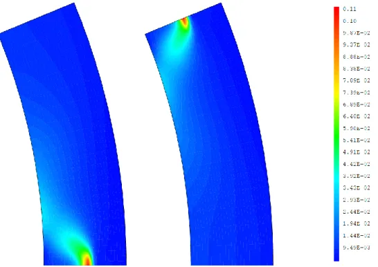
Cross-comparisons with ALCYONE simulations have shown that the time evolution of the average plastic hoop strain in the 45° shear band beneath the blister is correctly reproduced by the present calculation if only one eighth of the pellet is considered and if the blister is not dissymmetric. The mesh refinement was found to have very little impact which confirms that the chosen plastic strain criterion is numerically sound. It was also checked that the angular position of the blister crack had no impact on the results (see Figure 10) meaning that a prescribed radial displacement based on the average of the fuel external surface is adequate. In this respect, the important stress concentration in the cladding in front of the pellet radial cracks usually considered of great importance in PCI transient [7][9] (power ramps) appears of secondary importance for RIA calculations.
Figure 10 : Plastic strain distributions calculated at the end of the REP-Na8 in case the blister crack is situated in front of the plane of fracture (left) or the plane of symmetry (right) of the pellet fragment.
The crack in the blister is meshed explicitely with distinct facing nodes. At the beginning of the calculation, the displacements of the facing nodes are equal. At the time of the microphone event related to the blister cracking, these conditions are released. Figure 9 illustrates the dissymmetric development of plastic strains in the simulation with a 50% thick blister (1 = 5°, 2 = 10°, blister length on clad outer surface ~1.3 mm). Interestingly,
very high plastic strains tend to develop at the blister crack tip but also along the blister – clad interface which might be the reason for the blister – crack decohesion observed in Figure 5.
From the calculation, it appears that the plastic strain in the 45° shear band reaches in this case 2.8% at the time of failure of the REP-Na8 test, to be compared to the 3-10% measured by Hermann et al. [15] and to the previous estimate with ALCYONE of the plastic strain at failure (0.5%, see Figure 7). A realistic approach to clad failure induced by hydride blister cracking during a RIA obviously requires the development of a simulation tool able to model the whole circonference of the cladding tube and the evolving PCMI. The impact of blister geometry (length on outer clad surface, dissymmetry of the crack) has not been studied yet in spite of its potential great importance on plastic strains.
10 Moreover, the limited axial length of the blisters was not considered in this study since only 2D simulations were performed. It might as well contribute to the calculation of greater plastic strains more consistent with experimental measures.
7. Conclusions
In this paper, the thermo-mechanical response of a fuel rod containing a fictitious hydride blister has been studied by 2D plane strain simulations. The blister of increasing depth (25 to 90% of the clad wall thickness) is assumed to behave as the rest of the cladding material till a prescribed hoop stress is reached on the outer clad surface. The stress criterion is based on the Finite Element analysis of a laboratory hoop tensile test performed on a highly irradiated sample with a through-wall hydride blister. The 2D simulations of the REP-Na8 pulse test performed with ALCYONE led to a qualitatively good representation of the mixed failure mode encountered in RIA pulse transients on highly corroded fuel rods (in case significant spalling of the corrosion layer has taken place during base irradiation). The brittle failure of the hydride blister characterized by a radial crack is followed by the development of a diagonally orientated plastic shear band in the remaining clad ligament. A quantitative estimate of the plastic strains in the band has been obtained by the modeling of the whole cladding circonference and of a single dissymmetric blister. 3D calculations have to be performed since the limited axial length of the hydride lense might also change the plastic strain distribution.
Acknowledgements
The authors would like to thank AREVA and EDF for the financial and technical support to this work.
References
[1] T. Fuketa et al. (1997). Journal of Nuclear Materials (248) 249-256.
[2] T. Fuketa and T. Sugiyama (2009). Nuclear Fuel behavior during RIA, OCDE/NEA Workshop, Paris, France.
[3] J. Papin et al. (2003). Eurosafe Meeting, Paris, France. [4] J. Papin et al. (2007). Nuclear Technology (157) 230-250.
[5] V. Georgenthum et al. (2008). WRFPM Conference, Seoul, Korea.
[6] Desquines et al. (2004). Proceedings of the ASTM conference on Zirconium in the Nuclear Industry, Stockholm, Sweden.
[7] B. Michel et al. (2013). Nuclear Technology (182) 124-137. [8] Cast3M, http://www-cast3m.cea.fr/, [Online].
[9] J. Sercombe et al. (2012). Nuclear Engineering and Design (242) 164-181. [10] J. Sercombe et al. (2010). TopFuel Conference, Orlando, Florida, USA. [11] M. Le Saux et al. (2008). Journal of Nuclear Materials, 378 (1), 60-69. [12] B. Cazalis et al. (2007). Nuclear Technology, 157, 215-229.
[13] A. Hellouin de Ménibus et al. (2014). Journal of Nuclear Materials (449) 132-147. [14] V. Macdonald et al. (2014). Procedia Material Science (3) 233-238.
[15] Hermann et al. (2007). Proceedings of the 15th ASTM conference on Zirconium in the Nuclear Industry, Sunriver, Oregon, USA.
[16] H.M. Chung et al. (1998). Nuclear Engineering and Design (186) 411-427. [17] Le Saux (2010). PhD thesis, chapter 4, Ecole des Mines de Paris.