HAL Id: tel-02517768
https://hal.univ-lorraine.fr/tel-02517768
Submitted on 24 Mar 2020
HAL is a multi-disciplinary open access
archive for the deposit and dissemination of sci-entific research documents, whether they are pub-lished or not. The documents may come from teaching and research institutions in France or abroad, or from public or private research centers.
L’archive ouverte pluridisciplinaire HAL, est destinée au dépôt et à la diffusion de documents scientifiques de niveau recherche, publiés ou non, émanant des établissements d’enseignement et de recherche français ou étrangers, des laboratoires publics ou privés.
periphery of WEST & EAST tokamaks
Guillaume Urbanczyk
To cite this version:
Guillaume Urbanczyk. Interaction of High-Power waves with the plasma periphery of WEST & EAST tokamaks. Plasma Physics [physics.plasm-ph]. Université de Lorraine, 2019. English. �NNT : 2019LORR0181�. �tel-02517768�
AVERTISSEMENT
Ce document est le fruit d'un long travail approuvé par le jury de
soutenance et mis à disposition de l'ensemble de la
communauté universitaire élargie.
Il est soumis à la propriété intellectuelle de l'auteur. Ceci
implique une obligation de citation et de référencement lors de
l’utilisation de ce document.
D'autre part, toute contrefaçon, plagiat, reproduction illicite
encourt une poursuite pénale.
Contact : ddoc-theses-contact@univ-lorraine.fr
LIENS
Code de la Propriété Intellectuelle. articles L 122. 4
Code de la Propriété Intellectuelle. articles L 335.2- L 335.10
http://www.cfcopies.com/V2/leg/leg_droi.php
École doctorale "C2MP" ED 606
Sciences et Technologies
Thèse
pour l’obtention du titre de
Docteur de l’Université de Lorraine
présentée par
Guillaume URBANCZYK
Interaction of High-Power waves with the plasma
periphery of WEST & EAST tokamaks
Thèse soutenue publiquement le 29 Novembre 2019 à Nancy devant le jury composé de:
Prof. Etienne GRAVIER
Président du jury – ULorraine
Dr. Annika EKEDAHL
Rapporteur – CEA
Prof. Xinjun ZHANG
Rapporteur – ASIPP Chine
Prof. Kristel CROMBE
Examinatrice – UGent/ERM
Prof. Stéphane HEURAUX
Directeur de thèse – ULorraine
Dr Laurent COLAS
Co-directeur de thèse – CEA
Dr. Philippe JACQUET
Invité – CCFE Culham
ABSTRACT
Ion Cyclotron Resonance Heating (ICRH) in the H minority scheme can allow thermal ions to absorb up to half of the injected power. Meanwhile, ICRH heating can prevent heavy impurity accumulation similarly to broad ECRH [Sertoli 2017]. In order to benefit from ICRH in the core, waves must be coupled to the plasma from antennas whose location at the edge is subject to a trade-off between (1) efficient coupling and (2) impurity generation. This thesis presents mostly experimental observations made on these two aspects in EAST and WEST superconducting medium size tokamaks, on L-mode scenarios combining Lower Hybrid Current Drive from two launchers and D[H] minority heating by ICRH antennas. All ICRH antennas have been able to couple more than 1MW per antenna, with indications of efficient wave absorption. The heating efficiency changes consistently with the total power injected. However in some cases without low-Z materials coating (Li, B), heating effect may only last several hundred milliseconds (time-scale for impurity transport up to core plasma) after powering ICRH.
Lower Hybrid (LH) power helps improving ICRH coupling. Experiments reveal that fueling from the mid-plane not only helps to couple waves from nearby antennas like in other devices, but also has an impact on the scrape-off layer (SOL) density in regions that are not magnetically connected to the valves. Localized mid-plane nozzle valves allow in EAST better coupling compared to poloidally distributed valves. Core density control requirements for long-pulse operation, in particular in L-mode regime, however limit the amount of gas that can be injected. If injected from radially retracted points, gas can spread and help reducing sputtering yield on active antenna limiters by a combination of four effects: (a) reduce thermal effects by cooling down the SOL (b) improve coupling and therefore reduce the overall near-field amplitudes for a given RF power, (c) increase the electron mobility in the SOL and thus mitigate the excitation of parallel components of the electric field and (d) dilute impurities which are the main contributors to sputtering.
During ICRH, impurities can contaminate the plasma to a level detrimental for the operation, e.g. 100% of ICRH power radiated in many L-mode discharges in WEST and H-mode discharges in EAST. Tungsten (W) production measured by extreme ultraviolet spectroscopy increases significantly when an ICRH antenna
magnetically connected to W surfaces is powered, compared to a reference phase without ICRH. On some components such as antenna side limiters, the rise is larger than with a similar LH, NBI or ECRH power. The relative contribution of each object and physical process (RF-sheaths, fast ion ripple losses) to core contamination yet remains poorly known. Comparing antenna limiters with W-coating vs low-Z materials helped quantifying the role of these components. The core W content, in presence of divertor sources only, is correlated with the total injected power, either from ICRH or LH. Since 2018 the LH guard limiter tiles were W-coated. Their contribution to the core W content appears more important than divertor sources, particularly when the magnetically connected ICRH antenna is powered. Two-strap ICRH antennas magnetically connected to W components at the mid-plane already compromise high performance operations.
In addition to low-Z materials in regions magnetically connected to antennas, using arrays of more than two straps toroidally would allow near-field’s cancelation and RF-sheaths reduction. Other concepts (active limiters, TWAs) have been proposed but remain to be tested.
Key Words: Ion Cyclotron Resonance Heating (ICRH), Scrape-Off Layer (SOL), Radiofrequency (RF) Sheath, Wave coupling, Local gas injection, Impurity
Contents
1.
Introduction ... 8
1.1 Fusion in plasma devices ...8
1.1.1 What is a plasma ? ...8
1.1.2 Fusion for energy ...9
1.1.3 Fusion devices ... 11
1.2 Plasma heating and current drive systems in tokamaks ... 14
1.2.1 Neutral Beam Injection – NBI... 16
1.2.2 Electron Cyclotron Resonance Heating – ECRH ... 17
1.2.3 Lower Hybrid Current Drive – LHCD ... 18
1.3 Ion Cyclotron Resonance Heating system - ICRH ... 19
1.3.1 Waves Coupling ... 20
1.3.2 Waves Absorption ... 24
1.4 Plasma Edge Sheaths ... 27
1.5 Thesis outline ... 29
2.
Theory of ICRF waves and interaction with plasma ...33
2.1 Approximations ... 35
2.2 ICRF waves in the plasma ... 37
2.2.1 Dispersion Relation ... 37
2.2.2 Fast and Slow waves ... 42
2.3 Debye Sheath ... 46
2.4 ICRF-induced RF Sheath and DC Rectification ... 49
2.5 Impurities production ... 52
3.
ICRF experiments in tokamaks ...57
5
3.2 Experimental characterization of RF sheath effects ... 59
3.3 Trade-off relation between RF sheath excitation and coupling resistance increase ... 62
4.
Experimental setup ...64
4.1 EAST ... 64
4.1.1 General description ... 64
4.1.2 ICRF system in EAST ... 68
4.1.3 Fueling and pumping in EAST ... 70
4.2 WEST ... 72
4.2.1 General description ... 72
4.2.2 ICRF system in WEST ... 74
4.2.3 Fueling and pumping in WEST ... 76
4.3 Key diagnostics used in both devices ... 78
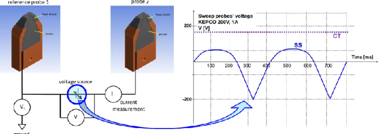
4.3.1 Langmuir Probes... 79
4.3.1.1 Langmuir Probes theory – I-V curve ... 79
4.3.1.2 Triple Probes ... 83
4.3.1.3 Implementation in EAST ... 86
4.3.1.4 Double probes in WEST ... 87
4.3.2 Spectroscopy ... 90
4.3.2.1 Ultraviolet spectroscopy... 91
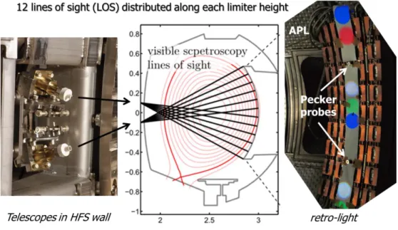
4.3.2.2 Visible spectroscopy ... 94
5.
ICRF coupling optimization with local gas puff ...99
5.1 Experimental method ... 101
5.2 Experimental results ... 105
5.2.1 Effect of gas injection on ICRF antennas loading ... 105
5.2.2 Effect of gas injection on SOL parameters ... 116
5.2.4. Gas injection influence on divertor heat loads in EAST ... 126
Summary of coupling experiments ... 128
6.
ICRH influence on impurity production ... 131
6.1 Experimental conditions and protocols ... 135
6.2 Links between ICRH and impurities production ... 137
6.2.1 Far-field effects... 142
6.2.1.1 EAST high field side wall facing an ICRF antenna ... 142
6.2.1.2 WEST divertor during H concentration scan ... 146
6.2.2 Divertor region, a combination of all effects ... 149
6.2.2.1 EAST divertor... 149
6.2.2.2 WEST divertor ... 155
6.2.3 Near-field effects 6.2.3.1 EAST B-port antenna Faraday screen and magnetically connected Ti plates ... 157
6.2.3.2 WEST antenna limiter and Faraday screen, and magnetically connected APL ... 159
6.2.3.3 EAST I-port antenna limiters surrounding ... 165
6.3 Estimate the contribution of LH grill limiters to core W contamination in EAST from LSN/USN comparisons. ... 172
Summary of impurity studies ... 175
7.
Conclusion ... 178
Annex ... 185
1 Modeling needs and tools for ICRF applications ... 185
1.1 COMSOL Finite Element Software... 185
1.2 Wave coupling modeling with TOPICA and RAPLICASOL ... 186
1.3 RF sheath modeling in SOL plasma with SSWICH ... 187
1.4 RF wave propagation and absorption in core plasma with EVE and TOMCAT codes . 190 2 Modeling tools for power exhaust estimations ... 192
7
2.2 Heat loads from infra-red inversion with TEDDY ... 194
3. S/XB coefficients function of energy to estimate different particle fluxes from visible spectroscopy ... 196
4. Overview of discharge 54528 discussed in chapter 5 ... 198
5. Coupling simulations with RAPLICASOL ... 200
5.1. Calculations for EAST B-port antenna ... 201
5.2. Calculations for WEST antennas ... 203
6. Calculations with SSWICH ... 209
7. Example of disruption caused by ICRF-induced core contamination with tungsten ... 211
8. Overview of discharge 54633 ... 212
9. Link between heat fluxes and sputtering in presence of ICRH ... 214
10. Isotopic ratio measurement in the edge with Hα and Dα lines fitting ... 220
11. ICRF wave properties in EAST and WEST ... 224
Bibliography ... 227
Acknowledgements ... 235
Publications and oral ... 240
Résumé en Français ... 241
Glossary ... 248
Notations ... 249
Résumé ... 250
1. Introduction
Nuclear fusion is a reaction in which two or more atomic nuclei are combined to form one or more different atomic nuclei and subatomic particles (neutrons or protons). The difference in mass between the reactants and products is manifested as either the release or absorption of energy. This difference in mass arises due to the difference in atomic "binding energy" between the atomic nuclei before and after the reaction. Fusion is the process that powers active or "main sequence" stars like the sun (Fig.1.1a), or high magnitude stars like the crab nebula (Fig.1.1b). Nowadays telescopes enable to observe various kinds of objects where gigantesque amount of matter can naturally meet together under tremendous gravitational forces. Surely the example we know the best is our sun (Fig.1.1a) and this is why we try to imitate it for creating a new, clean, sustainable and safe source of energy, the nuclear fusion.
Figure 1.1: Pictures of (a) our sun and (b) of the Crab Nebula (supernova)
1.1 Fusion in plasma devices
1.1.1 What is a plasma ?
The Plasma is one of the fourth fundamental states of matter, and is basically an ionized gas (Fig.1.2). It can be composed more specifically of ions, atoms which have some of their orbital electrons removed, and free electrons. Plasma can be generated either by heating or subjecting a neutral gas to a strong electromagnetic field to the point where an ionized gaseous substance becomes increasingly electrically conductive, like in a neon light tube when the gas is ionized (2000°C) by the
9
difference of potential between the anode and the cathode when you switch on an interrupter. This type of plasma considered “cold” can then be contained inside a glass tube to create light. Cols plasmas are also used a lot in the industry to replace vacuum, treat surfaces and wastes, etching at high precision … However these plasmas are far from the conditions required for fusion.
Figure 1.2: Four states of matter and transitions between them
1.1.2 Fusion for energy
Most likely nuclear fusion reaction to be used one day on nuclear fusion reactors based on reactivity (Fig.1.3) is also the one that happen at the edge of the sun between deuterium and tritium [G. Van Oost 2008]:
2 3 4 1
Figure 1.3: Fusion reaction rate as a function of temperature for three different reactions. The DT rate peaks at a lower temperature (about 70 keV, or 800 million kelvin) and at a higher value than other reactions commonly considered for fusion
energy. (https://en.wikipedia.org/wiki/Nuclear_fusion)
As can be seen on the eq.1.1, deuterium and tritium have to fuse together, but as they both have the same charge once ionized in a plasma, this is not about to happen easily. Both ions basically have to get close enough so that the weak interaction force becomes stronger than the Columbian repulsion and they can fuse together. Once this happens, products of the reaction are a helium nuclei and a neutron with a lot of energy (14MeV vs 4.8MeV on average for fission reactions) that can be collected by a coolant to produce electricity exactly as it has been done in nuclear fission for decades. Notice also that unlike fission, this reaction does not produce any long life radioactive element but only requires to manage tritium and materials activation under large particle fluxes which is nothing compared to products of a fission reaction, the so-called long life nuclear waste with high radiation level. This is probably one of the main advantages of the fusion, with the abundance of resources (D, T) and its remarkable safety.
Let’s now explain how we manage in practice to bring nucleus close enough to fuse together. Intuitively one can feel that bringing two magnets with the same polarity together takes energy, similarly bringing two ions with the same charge together takes energy. In plasmas, this energy can be seen as the temperature of the plasma, equivalent to the average kinetic energy carried by particles. Based on the plasma density that can be done in current devices and the efficiency by which particles are confined, temperature should be above 10keV which is more than 100 million degrees in order to start having the reaction happening (which is increasing
11
the D-T reaction cross-section as shown in Fig.1.3). A more accurate criterion taking three key parameters into account for fusion ignition can be derived from the energy balance of the reaction; this is the Lawson criterion [J.D. Lawson 1957]:
21
. .
e i3.10
/
n
T
keV s
(1.2)With n the density, Ti the ions temperature and τe the energy confinement time
which is the characteristic time by which the plasma loses its energy (heat). To understand this notion, an analogy can be made between the plasma and a house heated at 25°C while the temperature outside is only of 0°. An infinite confinement time would mean that the heater can be switched off and that the temperature in the house will never change, which is of course never the case because of heat diffusion. Now since the energy inside the house is proportional to its volume whereas the speed at which the energy flows out is only proportional to its surface, one understands why a bigger house will stay warm longer than a small one. For the same reason that building larger house allows keeping energy inside longer, building larger devices should also allow keeping the energy longer, and therefore more easily stay in regimes suitable for fusion reactions by maximizing the so-called confinement time.
The next objective is to maximize the triple factor in eq.1.2, either by increasing plasmas density (by injecting more gas), temperature (by heating the plasma), or their product (by increasing the magnetic field). Devices are highly constrained by operational and engineering limitations (materials, heat loads, magnetic field coils …) that in practice prevent from fulfilling what physics tells us to do (increase further the triple factor in eq.1.2). Physics limits the density for instance due to magneto hydrodynamic, engineering limits affect heating systems and the intensity of magnetic field that can be done, while interaction between plasma and material limits the damages that the device can sustain.
1.1.3 Fusion devices
Several concepts and devices can be used to make nuclear fusion reaction on earth:
- The inertial confinement uses lasers to shoot high density pellets of fuel [Pfalzner 2006], however this approach only allows about one shot lasting several nanoseconds per day because aligning another pellet takes time. This
approach is mostly used for military purpose.
- The Z-machine consists in suddenly discharging electricity stocked in pools (capacitors) through grills that are brought together by strong induced electric fields, compressing the fuel pellet in between, from about 2mm down to 0.16mm in 7ns (https://fr.wikipedia.org/wiki/Z_machine). This approach is mostly used to generate X-rays by Sandia laboratories in the US.
- Stellarators are plasma device that rely primarily on very complex external magnets to confine the plasma and not relying on current drive to induce an extra poloidal field to close the magnetic field lines like in tokamaks (https://en.wikipedia.org/wiki/Stellarator) [D.A Hartmann 2008].
Tokamaks were invented by Russians more than sixty years ago –
toroïdalnaïa kamera s magnitnymi katushkami – to confine a plasma in a toroidal chamber with magnetic coils. Tokamak is the concept that got most of the attention since the sixties
Figure 1.4: (a) 3D Schematic view of a Tokomak (courtesy by EUROfusion [FusionWiki]) and (b) 2D Poloidal cut of the plasma showing the core (hottest part), the edge (colder) the separatrix corresponding to the last closed surface and out of it
the Scrape-Off Layer (SOL)
The figure 1.4 shows the key elements of a tokamak. As a charged particle plunged into a magnetic field turns around it like represented by the red line in Fig.1.4a, we
13
can say that the particle is well confined within one Larmor radius if magnetic field lines are correctly closed, and there is the first challenge. Initially, toroidal field coils – that give to the tokamak its torus shape – produce a toroidal magnetic field. The problem is that this toroidal magnetic field is not homogeneous; it is inversely proportional to the radius, so decreases as we move from the center to the edge. This means that a particle turning around a field line will experience a stronger field – and so a stronger curvature – on one side than the other, giving rise to aBdrift that
deviate its trajectory vertically (for instance ions downwards and electrons upwards). To counter this effect, the inner poloidal field coils combined with the current flowing through the plasma induce another poloidal magnetic field, which added to the toroidal one, results in a total helical magnetic field lines wound on closed magnetic surfaces. With this configuration the curvature drift alternatively pushes the trajectories towards the outer and inner magnetic surfaces. Finally outer poloidal coils are added all around the structure for controlling the shape and position of the plasma according to the scenario. In a toroidal fusion power reactor, the magnetic fields confining the plasma are formed in a helical shape, winding around the interior of the reactor. The safety factor, labeled q or q(r), is the ratio of the times a particular magnetic field line travels around a toroidal confinement area's "long way" (toroidally) to the "short way" (poloidally):
. . p t R B d q r B d = = (1.3)
With R large radius, r a given radial location, Bp and Bt respectively the poloidal
and the toroidal magnetic field components. For instance when q=2, it means that particles make two poloidal loop when doing a toroidal one. If q increases, it means particles travel faster and faster in the poloidal direction compared to the toroidal direction, and follow trajectories with higher and higher pitch-angle compared to the toroidal direction. Since the plasma is only weakly confined along the field lines, it is almost homogeneous along magnetic surfaces, which allows assuming that any parameter radial profiles is quite homogeneous along magnetic field lines, and almost torodially. The term "safety" refers to the resulting stability of the plasma; plasmas that rotate around the torus poloidally about the same number of times as toroidally are inherently less susceptible to certain instabilities. The term is most commonly used when referring to tokamak devices. Although the same considerations apply in
stellarators, by convention the inverse value is used, the rotational transform, or i. Despite of great effort in all devices and equivalently fruitful discoveries resulting from each field of application, new methods of construction which have increased the quality and power of the magnetic fields improving stellarators performance, the tokamak remains the most promising concept for fusion energy, since best performance of other devices so far still remain much lower than these achieved in tokamaks (about three orders of magnitude difference in terms of Lawson criteria between stellarators and tokamaks (eq.1.2)).
1.2 Plasma heating and current drive systems in tokamaks
At the beginning of the discharge in a tokamak, the gas is first injected, cold, then rapidly ionized as density grows and collisions increase. Once there are positively charged ions and negatively charged electrons moving on opposite direction of the torus, a current appears. Due to Coulomb collisions, plasma has a small electric resistance, and this enables to heat it using Joule effect. Unlike most physics states, as plasma temperature T rises, collisional frequency and plasma resistivity decrease as 1/T3/2. This particularity of a plasma puts a limit to the use ofJoule effect whose efficiency decreases until it saturates once the plasma has reached temperatures of about few tens of millions degrees, still not enough for fusion reactions to take place (150 million degrees). Surely the current could still rise to compensate resistance decrease (PΩ=R.Ip² with PΩ the ohmic power and Ip the plasma
current) but here again, too strong current might leads to the brutal apparition of Magneto-Hydro-Dynamic (MHD) instabilities in the plasma often leading to a disruption (loss of plasma control). To prevent such event, the edge safety factor (q(r=0.95xR)=q95) should for instance be kept above some critical value (q95>2).
Other solutions presented in the following parts are needed [Y. Kazakov 2015]. One solution is to accelerate particles and send them into the plasma where they can collide with others and share their kinetic energy; this is the Neutral Beam Injection (NBI) detailed in the next subsection.
Other plasma heating methods rely on high-power electromagnetic waves [R. Koch 2015]. Plane wave is a physical quantity whose value, at any moment, is constant over any plane that is perpendicular to a fixed direction in space. Efficient heating
15
occurs when the wave frequency (=πf) resonates with the particle gyrofrequency (s = n.s+ k//.v//) with v// the parallel speed of a particle specie s in transverse
gyration at frequency s. Phase resonance between plane wave oscillating as
exp(-i+ik.r) with k the so called wave vector. Once accelerated, the resonant particles, if properly confined, subsequently transfer their energy and momentum to the bulk via collisions. The nature of the resonant particles and the value of n determine different ranges of frequencies summarized on Fig.1.5 and detailed in the next subsections. An analogy can be made between plasma and food heating with waves: in the same way waves in a tokamak resonate with charged particles, waves in a microwave oven excite water molecules based on their momentum. Note that wave frequency in a microwave oven is exactly the one of lower hybrid (GHz), only the power launched in a tokamak by a typical lower hybrid grill (100kW) is typically 2 to 3 orders of magnitudes above what is used to warm up food in microwaves (1kW).
Alpha heating is another solution a little bit more futuristic which requires to build tokamak big enough so that the helium nucleus emitted from the fusion reaction travels through a bigger volume of plasma, consequently losing more energy, so that at some point the plasma ignition conditions are fulfilled and its temperature remains stable without additional external energy; this is what DEMO (DEMOntration power station) wishes to achieve [DEMO]. First ITER (International Thermonuclear Experimental Reactor) should produce by fusion 10 times the power injected in the device to heat the plasma [ITER] (which is still remains smaller than the total amount of electricity necessary to power each system!). Significant heating of the burning plasma is expected from alphas (He product cf. eq.1.1).
Figure 1.5: Frequency spectrum with the three waves heating systems, and their respective power source name (in red) and the power usually available on one single
source (in blue)
Beyond heating the plasma to increase its temperature, it is also necessary as mentioned in the previous section to drive current trough the plasma in order to close the magnetic field lines and improve particles confinement. Current can be inductively driven by applying a voltage to the central solenoid (near the internal poloidal field coil in Fig.1.4) but the voltage resource stocked in capacitors before each discharge is limited and not sufficient to sustain current drive for long periods of time. Non-inductive current drive is then necessary to allow long discharges in steady state. Despite all auxiliary heating system are capable under certain conditions to drive current, lower hybrid frequency waves described in section 1.2.3 are the most efficient for this purpose.
1.2.1 Neutral Beam Injection – NBI
This technique consists in accelerating an ion beam with an electric field until hundreds of keV on nowadays tokamaks and until about 1MeV on ITER. This represents high energies that can be deposited through collisions in the plasma according a well-known direction (the one of the beam) [R. Koch 2008]. For now, world highest fusion power was achieved on JET tokamak (16MW) by injecting 22MW of NBI together with 3MW of ICRF (Ion Cyclotron Range of Frequency waves). NBI biggest challenge comes from the high energy beam neutralization before it is sent into the plasma. This neutralizing step is essential since as the objective of the tokamak is to confine charged particles, reciprocally none is supposed to enter it, so the beam must be neutralized before being injected. The difficulty of this step comes from the fact that as ion energy increases, it becomes much harder to neutralize (Fig.1.6). On ITER for instance, the size of the machine implies to inject beams at much higher energy than what is used on nowadays machines, so that it will penetrate deeper and be absorbed in the core. Otherwise, the beam decay length being proportional to its energy, if this last one is not high enough relatively to tokamak dimensions, most power would be deposited in the plasma edge, which is not suitable. From neutralization point of view, Fig.1.6 clearly shows that positive ions are not a good option for ITER, so it is planned to use negative ions which are easier to neutralize at high energies. Finally the charged beam that was not neutralized is diverted by a strong magnetic field and lost onto sacrificial materials that will be subject to further activation challenges.
17
Figure 1.6: Maximum neutralization frequency for deuterium and hydrogen ions as a function of beam energy [R. Koch 2008].
1.2.2 Electron Cyclotron Resonance Heating – ECRH
The Electron Cyclotron Resonant Heating consists in sending a wave in the electron cyclotron frequency range – defined as (Ωce=e.B0/me Є 100→200GHz) with e
the elementary charge, B0 the magnetic field and me the electron mass – which the
electromagnetic field will accelerate electrons that rotate around magnetic field lines at the same frequency [Westerhof 2008]. First thing to notice is because the magnetic field is inversely proportional to the radius r, so does particles gyrofrequency, which can be rewritten such asce( )r =. /e m re. . This means that the position of the
resonance can be controlled either by adapting the magnetic field or using gyrotrons with different frequencies. Moreover, the higher the frequency, the smaller the wavelength in vacuum the antenna (L =c f/ ), which is another advantage of ECRH antennas which can be small since the wave propagates in similar fashion as an optical beam. The wave can even be conveniently reflected on mirrors, allowing selecting different incidence angles and playing with this obliquity to drive current. As it is written on Fig.1.5, a gyrotron is used to generate such high frequency waves and can deliver several MW power. Since ECRF wave freely propagates in vacuum, there is not difficulty to couple them to the plasma unlike waves in lower hybrid or ion cyclotron range of frequencies. With such power that can be conveniently sent and absorbed in very precise locations, ECRH is a very efficient system not only for heating plasma or driving current, but its numerous assets are also very useful to control plasma [Stober 2012] during the start-up phase, and even treat MHD
instabilities such as:
- Sawteeth modulations [A. Mück 2005]; quasi-periodic relaxation that is commonly observed in the core plasma near q=1 surfaces and causes a sudden drop in the temperature and density in the center of the plasma. - Neoclassical Tearing Modes [F. Felici 2011]; a metastable mode and formation of a “seed island” triggered by a sufficiently large deformation of the bootstrap current and which can grow and lead to degraded confinement or ultimately disruption.
The bootstrap current is a Neoclassical toroidal current produced in the presence of a pressure gradient, associated with the existence of trapped (banana) particles in toroidal magnetic confinement systems. These trapped particles must be able to complete their (banana) orbits, so a requirement for the existence of the bootstrap current is νei < νb (the collision frequency is less
than the banana bounce frequency). The difference in particle density on banana orbits crossing a given radial position r then leads to a net toroidal current at r. The bootstrap current is estimated (roughly) as [Miyamoto 2005]
b . 1 p a dp j R B dr − (1.4)
Here, a/R is the inverse aspect ratio, Bp the poloidal magnetic field, and p the
pressure. More precise estimates can be made by simulating particle orbits. Finally by depositing power at the center, ECRH can also prevent impurity accumulation in the core [Sertoli 2017]. For these reasons, ECRH could for instance be used in WEST to cure core contamination by impurity, while it is envisaged as the first heating system to be implemented on ITER, with 24 gyrotrons of 1MW.
1.2.3 Lower Hybrid Current Drive – LHCD
Lower Hybrid frequencies (ωLH = [(Ωci.Ωce)-1+ ωpi-2]-1/2 ~ few GHz) are in
between electron and ion cyclotron frequencies with ωpi the ion plasma frequency.
They are generated by klystrons capable of delivering several kW each. Several klystrons are added in parallel to generate high power LH waves, separated on different wave guides until the grill where they enter the plasma [Ignat D.W. 1981]. Those waves are evanescent under relatively high densities (~7.1017m-3), which makes
19
where they would suffer from excessive heat loads. Gas puffing is used on several devices to locally increase densities in front of grills [Ekedahl 2009], and keep them far enough from the plasma. Thanks to their large parallel electric field, LH waves also have the interesting property of – Landau – damping very efficiently at high parallel phase velocities to the electron thermal speed (v||≥2.5vte=2.5(Te/me)1/2). They
are consequently able to drive current in the plasma periphery where electrons temperature is lower (off-axis), allowing good control of plasma current profile. Nevertheless the current that LH waves can drive non-inductively is not sufficient to sustain all the plasma current with acceptable recycled power. The idea is then to use it mainly for shaping current profiles, building internal transport barriers and access attractive steady-state operations with high bootstrap current. ITER should enable to reach more than70% of bootstrap current, with high βN (=Thermal pressure/Magnetic
Presure~3) and good confinement [ITER]. The magnetic pressure is an energy density associated with a magnetic field. Any magnetic field has an associated magnetic pressure contained by the boundary conditions on the field. It is identical to any other physical pressure except that it is carried by the magnetic field rather than (in the case of a gas) by the kinetic energy of gas molecules. A gradient in field strength causes a force due to the magnetic pressure gradient called the magnetic pressure force.
1.3 Ion Cyclotron Resonance Heating system - ICRH
ICRH such as ECRH consists in sending waves in the plasma which going through damping will convert its electromagnetic energy into ions kinetic energy. Ions being much heavier than electrons though, their gyrofrequency is much lower (Ωci=qi.B0/mi). Tetrodes are capable of producing waves in this range of frequencies
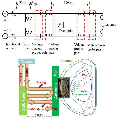
(10→100MHz) [Dumortier 2015]. Once generated, waves are conducted into coaxial lines towards the tokamak, where they will be coupled to the plasma by antennas. Note that their wavelength is like the tokamak size, of the order of several meters (L =c/ f ), making both their transport and coupling to the plasma – detailed in
the following part – very tricky problems since we cannot imagine antennas that would be as big as the tokamak itself. As can be seen on Fig.1.7 below, if the antenna is not well matched with the plasma (which must be optimized with the matching system), the wave is not well coupled, therefore reflected back in direction of the generators, which could induce severe damages on the tetrodes. A stub tuner can also
be used like in EAST, in order to adapt antenna impedance with the one of the plasma, and to prevent the reflected power to reach and damage the generators by reflecting most of it back towards the antenna. Otherwise the service stub which is a transmission line of length λ/4 connected to a load, with λ the ICRF wavelength, like in WEST. These safety systems are essential, thus those multi-reflections give rise to a standing wave with very high voltages, which if overcome a critical value may threshold arcing, damaging the system. We will now detail the key steps of ICRH process, namely waves coupling and absorption in the plasma.
Figure 1.7: Illustration of a typical RF system with waves emitted by generators and carried by transmission lines up to antennas radiating under plasma, and wave propagate up to a resonance layer were they can be absorbed by charged particles
1.3.1 Waves Coupling
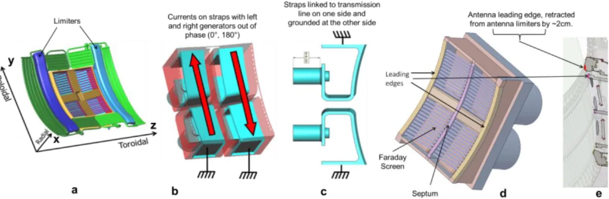
Figure 1.8: Example of ICRF antenna geometry (WEST-like) with the straps (c), the Faraday screen, the septum (d) and the limiters (a) with a poloidal cut of all
21
components (e). Key geometric dimensions are defined. Currents are represented on the straps of the antenna (b) and represent a case of most used dipole phasing (0, π). ICRF waves are excited by current straps in the antenna (Fig.1.8c). Those are typically about 50cm high (Lstrap) for 10cm large (δstrap) and are positioned almost
perpendicularly to the total magnetic field [Dumortier 2015] (Fig.1.8a). The distance between the straps also plays an important role for the wave spectrum excited (Fig.1.9). Current Jant flows in the strap according to the poloidal direction and
consequently excites mainly the poloidal electric field (Fig.1.8b) parallel to waves trajectories over a gyroperiod. This can also be seen as a voltage V0 proportional to
the current Jant and applied from the transmission line on one side of the straps, and
grounded on the other side (Fig.1.8c). The ICRF wave is a plane wave that can be characterized by its frequency close to Ωci, its refractive index n, its amplitude and
phase (between two straps). Those are usually condensed in the form of a triplet (k, E, B) composed of the wave vector (k=n. /c) and both electromagnetic field components. From those parameters can be deduced its propagation properties and this will be done in the next chapter. We will see that if the plasma parameters are favorable, the wave can propagate normally until the plasma core where it can be damped to ions thermal velocity, else it may either vanish or be reflected. The coupling resistance Rc (Ω/m) is an indicator of the efficiency of this process [Louche
& Koch 2015]. It can be estimated from voltage and current probes measurements in transmission lines (U, I), and φ the phase difference between voltage and current signals measured by a phase detector. The coupling resistance can then be calculated as follow:
(
/)
.exp( )C
R = U I i (1.5)
The bigger the coupling resistance, the more power Pt can be transferred to the
plasma as can be seen on the following formula:
2
. . / 2 t C Strap ant
P =R L J (1.6)
In practice, the key parameters to play on to optimize the coupling efficiency are the wave vector (k||=n||ω/c) and the phase between straps. For instance in the case of a
four straps antenna we can represent the normalized coupling resistance - proportional to the power spectrum Pt – in function of the wave vector for different phases. It can
be seen on Fig.1.9, that the highest values of k|| are obtained for the dipole phasing (0,
π) corresponding to the case in Fig.18b and the blue curve in Fig.1.9. Nevertheless its corresponding maximum values on the spectrum are relatively low compared to other phases, which will make its coupling harder. Note also that its spectrum is symmetrical so it can be used to heat the plasma. We will see on the next part that the bigger wave vector is, the better the absorption. Others phasing such as (0, π/2, π, 3π/2) or (0, -π/2, -π, -3π/2) lead to non-symmetrical spectrums, meaning the power is deposited asymmetrically in the plasma, which can be used to drive current. Monopole phasing (0, 0, 0, 0) was not represented on the left graph since its low k||
modes (also called coaxial modes) are an order of magnitude above others phases – as can be seen on the right graph – so that information would be hard to extract from the graph.
Figure 1.9: Power spectrum in function of the parallel wave vector for different phases of an EAST-like 4-strap antenna. Monopole phasing case is represented separately as its coaxial modes (black peaks) grow high compared to other phases.
We will see in the next chapter that the reason why ICRF waves are so hard to couple is because like LH waves, to propagate normally they need to reach a minimal density (~1018m-3) bellow which they are evanescent. From this assumption we can
already imagine a very simple model represented on Fig.1.10, on which an electric field E0 excites a wave (Ei,
k
v) withk
v the wave vector components in the directions23
perpendicular to the magnetic field (parallel direction close to the toroidal direction in Fig.1.8a) in the evanescent region of width δev, so a part of the wave manages to
tunnel through this layer and reach the region where it can propagate (Et,
k
p) whileanother one is reflected back (Er,
k
v). In a Cartesian frame (x,y,z) like in Fig.1.8a, allRF quantities are assumed to oscillate as exp(-i0t+ikzz), where 0 is the wave
pulsation, z is the direction of the confinement magnetic field in a flattened tokamak and kz is the characteristic parallel wavevector. Wave propagation is investigated
along direction x, representative of the radial direction in our slab approximation, i.e. plane wave amplitudes vary with x only. For the sake of simplicity the RF electric field E is assumed purely transverse to z, with a polarization along direction (x,y). This situation is representative of the Fast magnetosonic wave in a tokamak environment when the poloidal wave vector is null (ky=0). Space is divided into two
separate zones. The RF wave is assumed evanescent in the region x<0, i.e. we postulate that the complex RF electric field amplitude Ey transverse to x can be
described by the equation
( ) ( )
0 ; 02
2 − =
xxEy kv kz Ey x x (1.7)
Where kv2(kz) is implicitly assumed real positive. Similarly the RF wave is
propagative in the region x>0 and obeys the equation
( ) ( )
0 ; 02
2 + =
xxEy kp kz Ey x x (1.8)
Figure 1.10: Illustration of a simple model of wave propagation in the plasma periphery
Power carried by each wave can be assessed by the pointing vector representing the directional energy flux (the energy transfer per unit area per unit time) of an
electromagnetic field and defined as * *
0
Re( ) Re( ) /
x x y z
P = E H = E B
. Then writing the power conservation at the interface between both domains, we get:2 * 0 0 2 2 0 4 . p v exp( 2 ) exp( 2 ) t i r v v v v p v k k E E P P P k k k k = − = − − + (1.9)
By analogy with eq.1.5 we can write:
(
2)
2 / . exp( 2 )
C Strap ant t v v
R = L J P − k (1.10)
From this last relation, it appears clear that the coupling resistance decreases exponentially both with the evanescent length and the wave vector module.
1.3.2 Waves Absorption
Once the wave reaches the region where the density is high enough, it starts propagating normally until reaching positions where it can resonate and damp its electromagnetic power on surrounding ions. ICRH tends to create high-energy tails in the distribution function of the heated particles. For heating at the n-th cyclotron harmonic, the diffusion coefficient is of the form:
2 2 2 1 1 1 n n n s k v D J E J E J E ⊥ ⊥ − + + − − + + (1.11)
where E+ and E- are, respectively, the left-hand and right hand components of the electric field:
(
x y) / 2
E
+=
E
+
iE
;E
−=
(
E
x−
iE
y) / 2
(1.12) Ions absorb the energy of the wave. Various scenarios can rely on many different mechanisms of absorption [Louche & Koch 2015] [Kazakov 2015] :- Fundamental resonance (ω0=Ωci): Wave electric field rotates at the same
25
0 ²
D K E+ with K a constant (1.13)
This kinetic energy is then redistributed to other ions through collision process and the bulk plasma heats up. Besides, notice that this technique cannot be used in case of single ion species plasma since the wave electric field rotates in the opposite side as the ion gyromotion, so that no energy can be transferred. This is the screening effect and can be understood by writing the wave
polarization as a function of plasma particles gyrofrequency:
0 0 ci ci ci ci ci ci N E E N + − − − + + (1.14)
One understands that in a plasma with only one ion species i, at the ion cyclotron resonance, heating the fundamental N=1 does not work because the resonant wave component is absent (left-hand polarized component of the wave E+ vanishes). This will be rigorously demonstrated in the next chapter.
For this reason fundamental can be used only on multiple species plasmas, and lead to the so called ion-ion hybrid (or Buchsbaum) resonance.
- Harmonics resonance (ω0=N.Ωci with N an integer higher than 1) consists in
sending waves at frequency multiple of the fundamental. Absorption occurs when the wave reaches a region where its frequency is a multiple of ions gyrofrequency. One advantage is that it can be used to heat a single species plasma since the polarization of a harmonic wave in the direction of ion rotation is not null (no screening effect). Yet, another problem at constant polarization is that over its gyromotion, ion is equally accelerated and decelerated, so that on average, no energy is transferred. This problem is overcome by sending waves with inhomogeneous electric field, so that the acceleration phase can be made stronger than the deceleration one. This method can be used with relatively good efficiency for low values of N, thus it can be shown expressing the quasi-linear diffusion coefficient of the Nth
harmonic that it decreases exponentially with N [Koch 2015]: 2( 1) 2 N N s k v D E − ⊥ ⊥ + (1.15)
Pay special attention on the distinction between wave screening effect at the fundamental on a single ion specie plasma and balance between acceleration
and deceleration over a gyroperiod. Both mechanisms are totally different, so that playing on the inhomogeneous character of the electric field would never allow heating single ion specie plasma at the fundamental.
- Minority Heating consists in having a plasma composed of several ions species with one in significantly smaller amount (<10%). The fact of having several species brings up another key phenomenon for ICRF called ion-ion hybrid resonance. Moreover, dynamic being dictated by the majority specie, waves sent with frequency corresponding to the minority specie fundamental (Ωci) are not screened anymore (eq.1.14). Damping now occurs in the zone
between each specie resonance surface. The minority ions receive the energy from the wave and spread it to others species by collisions. In practice1
1
H
isoften used as minority with2
1
D
in majority. The three-ion scheme also consistsin heating the fundamental of a minority whose resonance location falls in the ion-ion hybrid resonance range of both others majority species [Kazakov 2017], where the amplitude of the left-handed polarization can reach very high values.
- Majority Heating consists in heating the majority specie (>90%). This one also dictates the dynamic of the plasma, so that sending waves at the fundamental is not appropriate since large amount would be screened as mentioned previously. In this scenario, better efficiency is reached by sending waves at a harmonic of the majority specie gyrofrequency (eq.1.15). To further maximize the absorption, it can also be useful to create a population of fast ions, either by accelerating them with ICRH which can take some time, or inject them with NBI [Lerche 2019].
- Landau Damping is a non-collisional mechanism belonging to the kinetic theory of plasma waves, which means the condition of resonance does not only depend on the wave vector k and frequency ω but also on the particle speed v; it can be written v = ω/k. In the kinetic theory, particles energy distribution function is considered, so that a certain number of particles slower than the wave will feel acceleration while faster ones are to the contrary decelerated. The efficiency of this process is consequently based on a
27
electrons which are almost always maxwellian, can benefit from this process, mainly used by LHCD to drive off-axis currents where electrons are slower. - Transit Time Magnetic Pumping is conceptually the same as Landau damping
except that the energy transfer is not based on the electric field of the wave but on it magnetic component. It can also be seen as a Doppler shift.
- Mode conversion is the process by which a given wave spectrum (Fig.1.9) changes. Modes can be characterized by the excitation of particular values k||,
however, if the wave front meets discontinuities in the plasma, either surfaces with strong variations in the magnetic equilibrium or in densities, plane waves can be scattered and give rise to the excitation of others k|| modes which
propagation properties and absorption mechanisms can be very different and used in some scenarios.
Note that one can now imagine many heating scenarios combining those mechanisms. This constitutes a field of research particularly important for future devices, on which a single frequency could for instance at the same time heat the fundamental of the minority specie and a harmonic of the majority (ex: He3-T, H-D,
and three ions species [Lerche 2019]).
Several others interrogations might emerge from this brief introduction, but they will not be treated in further details since it would take us too far out of the scope of this thesis.
To evaluate the quality of the absorption, we talk about single pass absorption. It represents the percentage of power that can be absorbed when the wave crosses the bulk once (Fig.A4). Different scenarios lead to different absorption efficiencies, the optimal case being full single pass absorption, so that there would be a minimal number of reflections of the wave against the right cutoff at the edge (R=n//²), and
consequently a minimum of power losses in the periphery and on Plasma Facing Components (PFCs).
1.4 Plasma Edge Sheaths
Sheaths constitute one of the biggest challenges in plasma periphery since they arise as magnetic field lines intercepted any Plasma Facing Component (PFC)
[Chabert 1969]. Simply because of mass difference (me<<mi), electrons accumulate
faster than ions on PFC surface, forming a negatively biased layer that repulses electrons and attracts ions (an illustration of the process available on Fig.2.1). This can result in the formation of a positively biased layer in front of PFC surface, essentially populated by ions and only few Debye lengths thick (few millimeters);
0 ² B e De e k T n e = (1.16)
with
ε
0 the vacuum permittivity, kB the Boltzmann constant, Te and ne respectively theelectron temperature and density, typically few eV and about 1018m-3 in a tokamak
edge plasma. The separation of charges over this short layer naturally results in a big drop of the potential of the plasma with respect to the ground; the one also enables to equilibrate charged particles fluxes, by stopping electrons with too small energy and accelerating ions towards the wall, so that ambipolarity (quasi-neutrality) is preserved. Nevertheless, such equilibrium is reached at the cost of an increase of ions energy while flying across the sheath electric field. Over these accelerations, their sputtering yield increases, and beyond some critical value, ions become dangerous projectiles. The sputtering yield Yeff of a given ion on a given material is the efficiency by which
an ion with a given impact energy on a surface made of a given material can sputter an atom out of the solid structure. This can be simply be written as Yeff = Гin / Гout
with Гin the incident ion flux on the material and Гout the outer flux of atoms sputtered
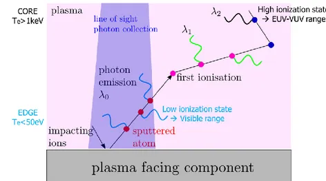
from the material. This will be further explained in the next chapters. Ions collide with heavy metal atoms, and over long periods, slowly modify PFC structure by displacing atoms, creating interstices, clusters and dislocations. Those effects not only have microscopic consequences on material properties – melting point, conductivity, mechanical strength – but they might also lead to void swellings which is a macroscopic dilatation of the material, and this could be faithful to a machine designed for economical purpose. Another critical and more immediate consequence of sheaths is if an atom is directly kicked-out from the structure. In this case, a high-Z atom (as tungsten and molybdenum which are favorite candidates to build vacuum vessels) is released into the plasma. As it moves from the edge deeper in the plasma, temperatures rise, and so do collisions frequencies. The atom will then be several times ionized, so that it ends up in the core sometimes after having been through more than twenty ionization states. Those are the so called high-Z impurities [Dux 2007], they badly decrease plasma performance by radiating energy that will not contribute
29
to fusion reactions.
Moreover, we will see in the next chapter that ICRH also plays an important role in the problematic of sheaths. Because the coupling of the wave is never perfect, a parasitic mode is excited, giving rise to a wave (called slow wave) with a high electric field component parallel to magnetic field lines (green arrow on Fig.2.1). The electric field of this wave will contribute to increase even more the electric field already existing across the thermal sheath. The process by which ICRF waves enhance sheath electric fields is the RF-rectification [Colas 2007] which theoretical aspects are addressed in the next chapter. At this point it is of prime importance for this thesis to have in mind that ICRH can play an important role in impurities production, which has been extensively studied experimentally and confirmed by simulations.
1.5 Thesis outline
This thesis takes place among other experiments involving ICRF to heat tokamak plasmas, either aiming at maximizing ICRF coupling efficiency or related to the characterization of RF sheath influence on the impurity production. The work is presented according these two topics which were studied experimentally in both EAST and WEST tokamaks and benchmarked with complementary simulations. One difficulty of this topic comes from the fact that despite peoples’ experience, most of us keep expecting ICRH to behave somehow gently in some regime allowing simultaneously to optimize wave coupling and mitigate impurity production. These aspects are however matter of trade-off governed by undutiful combination of non-linear processes, making any conclusion actually pretty sensitive to a wide set of parameters which cannot systematically be checked and are therefore often wrongly assumed to have negligible influence. Another aspect is that ICRF life becomes easier as the machines get larger. Big difficulty of nowadays tokamaks is that they are either small with respect to ICRF wavelength and energy deposition, either not designed in order to optimize scenarios with ICRF, which numerous requirements are not particularly challenging technologically but require very high level of anticipation and communication between RF physicists and engineers who do not always speak the same language and whose short term goals often appear hard to conciliate. Making bigger devices like JET, ITER or CFETR will improve the confinement of particles and energy, and allow benefiting from more favorable regimes than what can
be done in medium size tokamaks like EAST and WEST. In this work we will try our best to fix as many parameters as we can and explore different regimes and scenarios to hopefully extract information on optimal settings, relevant for more than only one tokamak, and try to extrapolate them up to future devices.
- Chapter 2 introduces key approximations to allow simplifying the model and use Maxwell’s equations, to assess ICRF wave properties. Thermal then RF sheath theories are then presented before explaining how it plays a key role for impurity production. It is finally shown how theory can be used in codes to simulate phenomena which ideally have been observed experimentally or which could be measured if the appropriate diagnostics were available.
- Chapter 3 summarizes the experimental context of the thesis
- Chapter 4 presents the experimental setup composed of EAST and WEST tokamaks, each having its peculiarities, but both having two ICRF and LH antennas and many diagnostics in common. Each tokamak is described along three axes comporting a general description, a more detailed description of the ICRF system and finally of the fueling methods. Details are finally given on Langmuir probes and spectrometers which have been extensively used in both devices.
- Chapter 5 first recalls some methods to optimize ICRF coupling such as minimizing the distance strap-cutoff layer, increasing the plasma density, increasing wave frequency, and the influence of different local gas injections in both devices in scenarios with additional LH power. By injecting gas locally, it is shown that LH power can help increasing ICRF coupling most likely by increasing density at the edge. Finally it is found that injection at the mid-plane is the best fueling option to improve waves coupling.
- Chapter 6 localizes and characterizes impurity sources related to ICRH. Different approaches are used in both tokamaks which are equipped with different materials and diagnostic; while WEST is a full-tungsten environment with visible spectroscopy allowing local and accurate characterization of impurity sources, EAST has plenty of materials differently connected to ICRF antennas but can only use UV spectroscopy to measure impurity in the core and extract relatively local information on where an interaction most likely took place.
31
- Annex contain further elements that are more or less important for the understanding of the thesis depending on lectors knowledge. Since the thesis will mostly focus on experiments, simulation results and brief descriptions of the codes can be found in the Annex. Overviews of several discharges used in the thesis are also provided. Finally, we provide elements in favor of a possible analogy between infrared and spectroscopic observations in RF environment, I hope these preliminary observation will inspire dedicated experiment to rigorously enlighten this idea.
33
2. Theory of ICRF waves and interaction with plasma
To help the lector visualize the plasma structure on the zone of interest for this thesis, the sketch in Fig.2.1 below was drawn. Physical process by which Slow Wave (SW) leads to the formation of a Radio-Frequency (RF) sheath, across which potential drops, enhancing ions sputtering yield and impurities release, is represented on this figure and will be extensively discussed in this chapter. Equations describing waves’ propagation in plasma (which an excellent overview can be found in [Louche & Koch 2015] and references therein) and RF sheaths processes [Chabert 1969] will be successively addressed bellow and solved in particular cases of interest.
Figure 2.1: Tokamak plasma border illustration;
Conducting metal object is on the left (purple zone), RF sheath plasma is the center white part which width is a few Debye lengths(λDe), and the plasma bulk is on the
right side (pink zone)
Since this thesis investigates the influence of high-power waves on tokamaks periphery, the understanding of how waves propagate in the plasma and how they interact with plasma facing components (PFCs) is of prime interest. On the Fig.2.1, we see that confining magnetic field lines (represented in blue) are mostly closed, but a few of them are opened and reach material surface. It exist a Last Closed Magnetic Surface (LCFS) represented by the dashed blue line, which represents the frontier between the well-confined plasma bulk and what is called the Scrape-Off Layer (SOL), region where all magnetic field lines are opened and intercept a PFC. Ion Cyclotron Range of Frequencies (ICRF) antennas are typically inside the SOL, such that limiters intercept many magnetic flux tubes. Maximizing the coupling efficiency of ICRF waves to the plasma consequently implies to deal with this SOL region. Several designs using different kinds of materials have been tried, thus in spite of all efforts to solve problems in the SOL, it seems that they merely can be minimized, trading-off between good coupling efficiency and robustness of the structure exposed to SOL plasma.
ICRF waves are mostly Fast Waves (FW) with a radial electric field (E⊥) that propagate until the core where they can give their energy to particles undergoing damping process. Thus some ICRF waves are also parasitically launched with an electric field component parallel to the magnetic field lines (E ), those are known as
35
bottom left of the Fig.2.1. This one takes into account the fact that the magnetic field is tilted of an angle θ compared to the toroidal direction. When such SWs propagate in the SOL, they locally create strong electric fields along magnetic field lines – as represented by the green arrow on the Fig.2.1 – to which charged particles react. Nevertheless electrons being much lighter than ions (me<< mi), they react faster and
accumulate on the surface of PFC. Ions are then attracted in order to balance fluxes ambipolarity, which basically means to keep the plasma macroscopically neutral. We consequently end up with lots of negative charges on one side and a cloud of positive charges on the other side, which results in a strong potential drop across a region only large of few Debye lengths (order of millimeter), called the Sheath. This leads to a strong electric field (ERF) represented by the big orange arrow on the Fig.2.1, the one
contributes to strongly accelerate ions, increasing their sputtering yield, which has consequences on impurities production.
2.1 Approximations
Let’s remind that if the lector feels confused about any notation used below, he (she) is welcome to take a look back to Fig.2.1 into which most important actors of the key processes we are about to discuss are represented and their meaning explained right after. Now in front of such a complicated state as the plasma, we need to make numerous approximation in order to perform calculations in simplified – though not always simple – cases. Each approximation is preliminary introduced and justified bellow:
1) Fully ionized plasma → Free charges (neutrals neglected)
2) Cold plasma → Effects of first order perturbed kinetic pressure are negligible when compared to perturbed magnetic forces such that everything happens as if Te ≈ Ti ≈ 0 eV.
3) Collisionless plasma → Thermal dissipation by binary collision neglected
4) Charge ambipolarity → Quasi-neutrality: n0 ≈ ne- ≈ nions
5) ICRF wave monochromatic ( ⎯⎯⎯→−/ t Fourier i) and planar
( Fourier ik
⎯⎯⎯→ ), ω and k being respectively the wave pulsation (ω=2πf) and the wave vector.
7) Fluid immobile in the absence of wave →vs = δvs (small fluid
perturbation caused by the wave),
vs being the speed of species s; in fully ionized plasma s can either be an ion i
or an electron e
8) No static electric field in the plasma → E = δE
9) Total magnetic field is the superposition of confining and wave magnetic fields → B = B0 + δB
Note that terms with δ correspond to very small perturbation (ex: δB << B0)
10) No current source → jext = 0 (wave is studied as coming from
infinity, no antenna considered)
It is worth listing all approximations to really take conscience of how many simplifications we made to bring expressions into a mathematically appreciable state. This gives a small idea of how complex is the plasma and how complicated it may become – not even thinking about taking everything into consideration – but only if we went further in the plasma core where already several approximation do not hold anymore.
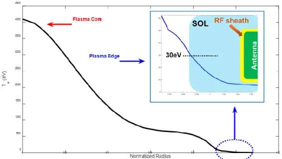
Figure 2.2: Typical temperature profile of a plasma in EAST (Shot n°62946 with 2.6MW LH, 1MW ICRF and 400kW ECRF) showing that we can reasonably make a
37
2.2 ICRF waves in the plasma
In order to visualize from the beginning the philosophy of the calculations we are going to do now, the Fig.2.3 represents the mains blocks and the coherence between them that will guide us all along.
Figure 2.3: Illustration of the following ICRF waves theory calculations
2.2.1 Dispersion Relation
Now we just have to follow the scheme on Fig.2.3, making the appropriate simplifications quoted in section 2.1, and using coordinates systems established on Fig.2.1. We start by writing respectively the Faraday and Ampere Maxwell’s equations: B E t = − (2.0) 0 2 1 E B J c t = + (2.1)
Where c is the speed of light. We then take the rotational of the eq. 2.0 and commutate time partial derivative with rotational and substituting the rotational of the magnetic field by eq. 2.1, we get the wave equation:
2 0 2 2
1
.
E
(
ext)
E
J
J
c
t
t
+
= −
+
(2.2)According to the 10th approximation J
![Figure 1.4: (a) 3D Schematic view of a Tokomak (courtesy by EUROfusion [FusionWiki]) and (b) 2D Poloidal cut of the plasma showing the core (hottest part), the edge (colder) the separatrix corresponding to the last closed surface and out of it](https://thumb-eu.123doks.com/thumbv2/123doknet/12741361.357839/16.892.137.758.588.915/schematic-tokomak-courtesy-eurofusion-fusionwiki-poloidal-separatrix-corresponding.webp)
![Figure 3.1: Example of core impurity screening with H minority ICRH in D plasmas in JET [Lerche 2016]](https://thumb-eu.123doks.com/thumbv2/123doknet/12741361.357839/61.892.265.604.580.865/figure-example-impurity-screening-minority-icrh-plasmas-lerche.webp)