Airblue: A System for Cross-Layer
Wireless Protocol Development
The MIT Faculty has made this article openly available.
Please share
how this access benefits you. Your story matters.
Citation
Ng, Man Cheuk et al. "Airblue: A System for Cross-Layer Wireless
Protocol Development." in Proceedings of the ACM/IEEE Symposium
on Architectures for Networking and Communications Systems
(ANCS), 2010, 25-26 Oct., La Jolla, Calif.
As Published
http://ieeexplore.ieee.org/stamp/stamp.jsp?
tp=&arnumber=5623848
Publisher
Institute of Electrical and Electronics Engineers
Version
Final published version
Citable link
http://hdl.handle.net/1721.1/71832
Terms of Use
Article is made available in accordance with the publisher's
policy and may be subject to US copyright law. Please refer to the
publisher's site for terms of use.
Airblue: A System for Cross-Layer Wireless Protocol
Development
Man Cheuk Ng, Kermin Elliott Fleming, Mythili Vutukuru, Samuel Gross,
Arvind, and Hari Balakrishnan
CSAIL, Massachusetts Institute of Techonology
{mcn02,kfleming,mythili,sgross,arvind,hari}@csail.mit.edu
ABSTRACT
Over the past few years, researchers have developed many
cross-layerwireless protocols to improve the performance of wireless
networks. Experimental evaluations of these protocols have been carried out mostly using software-defined radios, which are typ-ically two to three orders of magnitude slower than commodity hardware. FPGA-based platforms provide much better speeds but are quite difficult to modify because of the way high-speed designs are typically implemented. Experimenting with cross-layer pro-tocols requires a flexible way to convey information beyond the data itself from lower to higher layers, and a way for higher lay-ers to configure lower laylay-ers dynamically and within some latency bounds. One also needs to be able to modify a layer’s processing pipeline without triggering a cascade of changes. We have devel-oped Airblue, an FPGA-based software radio platform, that has all these properties and runs at speeds comparable to commodity hard-ware. We discuss the design philosophy underlying Airblue that makes it relatively easy to modify it, and present early experimen-tal results.
Categories and Subject Descriptors
C.2.1 [Computer-Communication Networks]: Network Archi-tecture and Design – Wireless communication
General Terms
Architecture, design, experimentation.
Keywords
Wireless, Software-Defined Radio, Airblue, Bluespec, cross-layer.
1.
INTRODUCTION
In recent years, researchers have developed a large and grow-ing set of protocols and algorithms to improve the throughput and capacity of wireless networks. These schemes span the physical (PHY), MAC, and network layers of the protocol stack. Some ex-amples include interference cancellation [1], ZigZag decoding [2],
Permission to make digital or hard copies of all or part of this work for personal or classroom use is granted without fee provided that copies are not made or distributed for profit or commercial advantage and that copies bear this notice and the full citation on the first page. To copy otherwise, to republish, to post on servers or to redistribute to lists, requires prior specific permission and/or a fee.
ANCS’10, October 25-26, 2010, La Jolla, CA, USA Copyright 2010 ACM 978-1-4503-0379-8/10/10 ...$10.00.
Conflict Maps (CMAP) [3], the SoftPHY interface [4, 5, 6], Sam-pleWidth [7], Analog Network Coding [8], MIXIT [9], VWID [10], ODS [11], and SWIFT [12].
A common theme in all these schemes is that they embody some form of cross-layer design, i.e., additional information is passed from lower to higher layers and higher layers exercise some con-trol over lower-layer decisions. For example, the SoftPHY inter-face [5] extends the receiver PHY to send to higher layers confi-dence information about each bit’s decoding, so that those layers can perform better error recovery [4], bit rate adaptation [6], di-versity routing [9], and so on. In fact, even the simple example of using the receiver’s signal-to-noise ratio (SNR) to determine a transmit bit rate is an example of PHY-MAC cross-layer informa-tion. Given the strong real-world interest in high-speed wireless networks, we expect a significant amount of continuing research in the area of cross-layer protocols.
The effort required to implement any high-performance wireless protocol from scratch is enormous. Therefore, one would like to start from a base implementation of, say, 802.11. The problem with this approach is that commodity hardware implementations offer no opportunity for making changes while the Software De-fined Radios, like GNUradio [13], do not offer sufficient perfor-mance for cross-layer experiments. Platforms like WARP [14] and SORA [15] can provide high speeds but are still quite difficult to modify for cross-layer experiments, as we show later. In this paper we identify two properties that are essential for modular refinement, i.e., the ability to make changes in one module of a system without having to understand or make changes to the rest of the modules in the system. These properties are latency-insensitivity and data-driven control. We believe that if the base protocol implementation does not have these properties, then it is quite difficult to modify for cross-layer protocol implementation. The need for these properties also shows up in pure software implementations on multicores.
In this paper we describe Airblue, an FPGA-based wireless plat-form designed especially for cross-layer experimentation. It sup-ports speeds comparable to commodity 802.11 hardware but is de-signed with modular refinement in mind. Airblue is also dede-signed to pass additional information up from the PHY layer to the MAC layer using annotated streams and to let the MAC reconfigure the
PHY in sub-microseconds. The main contributions of this paper
are (i) a working system built using sound design principles with unique capabilities for cross-layer experimentation, and (ii) a set of preliminary results to show that several important mechanisms needed for cross-layer protocols can be implemented efficiently. Paper organization: We first present related work in §2. Then, we discuss several concrete examples of cross-layer protocols (§3), and identify three requirements for each protocol: the information that needs to be conveyed from the lower to higher layers; the
dy-namic reconfiguration of the lower layer required by higher layers; and the modules in the PHY or link layers that need to be changed substantially. In §4, we discuss the properties an implementation must have for modular refinement, regardless of whether it is im-plemented in hardware or software. In §5, we describe the Airblue platform and our implementation of the 802.11 physical and link layers. In §6, we describe the modifications we made to the base implementation to implement various cross-layer protocols. We discuss the limitations of Airblue in §7, and conclude in §8.
2.
RELATED WORK
A variety of platforms have been proposed in the past few years to facilitate the development of new wireless protocols. These plat-forms span the entire design space of hardware and software imple-mentations of the PHY and MAC. On one end of the spectrum are Software Defined Radio (SDR) platforms such as GNURadio [13] and Vanu [16], which provide the flexibility required to modify all the layers of the stack. An SDR usually consists of an RF front-end connected to a commodity PC through a peripheral IO interface, with all the processing starting from the application layer down to the baseband being done on the PC.
However, SDRs are bandwidth-limited by the CPU on a PC and do not scale easily to handle commercial throughputs. One there-fore has to apply more sophisticated parallel programming tech-niques on multicores. This is the approach adopted in the SORA platform [15], which augments the SDR architecture with a more capable FPGA and applies a variety of application-specific par-allel programming techniques to achieve throughput comparable to 802.11 hardware. It stores pre-computed waveforms of time-critical data such as the acknowledgment frames, so as to meet the stringent protocol timing requirements. This implementation is im-pressive, but is not convenient for developing new protocols for several reasons. First, the designer of a new protocol must man-ually re-partition the software blocks to multiple CPU cores and the time-critical protocol portions to the FPGA, even after modi-fying a small number of blocks. In a recent paper by the devel-opers [17], when the authors change the 802.11b PHY to perform more complicated decoding, the PHY no longer meets 802.11 tim-ing when runntim-ing on a stim-ingle core. They admit that further opti-mizations that exploit the computational power of additional cores are required to meet the performance target. Second, it is impos-sible to achieve microsecond-latency communication between the MAC and the PHY, making it hard to implement several cross-layer mechanisms that require such communication (e.g., sending chan-nel quality feedback from the PHY in the link-layer ACK). As an aside, SORA also has a form-factor concern: an 8-core PC would be much larger than is convenient for mobile experiments.
Another example of extensions to SDRs is work by Nychis et al. [18] which proposes a modular MAC architecture that is flex-ible to implement the MAC of various protocols. They demon-strated the effectiveness of their approach by modifying the GNU-Radio platform which involved moving the computation of the time-critical MAC functionality onto the front-end FPGA, to al-low high-speed implementation of some (not all) MAC protocols. However, their system cannot achieve realistic throughputs of many Mbps because the PHY processing is still done in software.
In general, FPGA-based PHYs provide a good trade-off between programmability and low latency. Although a design running on an FPGA is typically slower than its Application-Specific Integrated Circuit (ASIC) counterpart, it outperforms the corresponding soft-ware implementation by two orders of magnitude. FPGAs leverage fine-grain parallelism and are fast enough for most experiments.
The closest example to our work is Rice WARP [14], a tightly
coupled system consisting of a software MAC and a PHY base-band implemented on an FPGA. The basebase-band PHY is imple-mented as Verilog blocks generated using Xilinx System Gener-ator in Simulink [19, 20, 21]. WARP provides a library of param-eterized modules that can be assembled using the graphical user interface of Simulink. A chief difficulty in using WARP, as we ex-plain in §4, is that its hardware PHY is not designed with modular refinement in mind. As a result, implementing protocols that re-quire PHY modifications can only be carried out by experienced users with a deep understanding of the whole design. Nevertheless, WARP can be easily modified to develop protocols that require only modifications to the software MAC.
There is a rich history of network and transport layer proto-cols implemented as composable collections of software process-ing modules. For example, Click [22] provides the ability to write and configure network processing elements easily. However, such systems do not address the issues that arise in designing the PHY and MAC layers of the network stack, which are more computa-tionally intensive.
All platforms mentioned above lie on different points of the per-formance and flexibility trade-off curve: they either trade flexibility for high performance or vice versa. Airblue differs from previ-ous works in the sense that that it is a high-performance platform which is also flexible. The enabling factor is the architecture of Airblue which follows two design principles: latency-insensitivity and data-driven control. These two principles allow developers to perform localized modifications without requiring changes to the rest of the system. Note that these design principles are platform-independent and can be used to develop high-performance and modular implementations on other FPGA platforms such as SORA or WARP.
3.
CROSS-LAYER PROTOCOLS
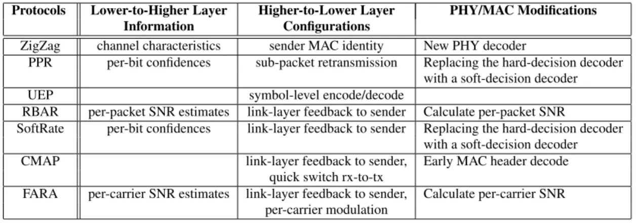
The research literature has many examples of cross-layer wire-less protocols, which are characterized by the use of information from higher or lower layers to achieve performance gains. Con-ceptually, most of these ideas can be implemented by extending existing standards like 802.11. We survey some examples of such protocols in this section, and identify the cross-layer interaction re-quirements as well as the modifications needed on top of an 802.11 implementation. The examples are summarized in Figure 1. Interference cancellation: Interference cancellation is a popular technique at the physical layer to decode multiple transmissions simultaneously. ZigZag [2] combats interference by using two in-stances of two collided packets, the second instance comes from a retransmission, to recover each of the individual packets. Imple-menting ZigZag requires new decoding logic in the 802.11 PHY, and some exchange of information between MAC and PHY. For example, the ZigZag decoder in the PHY must know the MAC ad-dress of the sender while it is decoding a packet, in order to track
the sender-specific frequency offset and compensate for it.1
Error recovery: Improving error recovery algorithms and mod-ifying them to suit application requirements can greatly increase application throughput. We consider two examples. Most link lay-ers in wireless data networks retransmit entire frames on even a single bit error. In contrast, the PHY in partial packet recovery
(PPR)[4] computes and exports per-bit confidence information or
SoftPHY hints, using which the link layer identifies and requests a retransmission of only those bits with low confidence. Unequal
error protection (UEP)[23] is another example of a technique that
1This way of implementing ZigZag is different from the
Protocols Lower-to-Higher Layer Higher-to-Lower Layer PHY/MAC Modifications
Information Configurations
ZigZag channel characteristics sender MAC identity New PHY decoder
PPR per-bit confidences sub-packet retransmission Replacing the hard-decision decoder
with a soft-decision decoder
UEP symbol-level encode/decode
RBAR per-packet SNR estimates link-layer feedback to sender Calculate per-packet SNR
SoftRate per-bit confidences link-layer feedback to sender Replacing the hard-decision decoder
with a soft-decision decoder
CMAP link-layer feedback to sender, Early MAC header decode
quick switch rx-to-tx
FARA per-carrier SNR estimates link-layer feedback to sender, Calculate per-carrier SNR
per-carrier modulation
Figure 1: Examples of cross-layer protocols and their implementation requirements.
modifies the standard error recovery algorithms. It is known that an application’s throughput and loss rate requirements can be bet-ter met by allowing the application to control the mapping from the data payload to the PHY modulation and coding. For example, video applications may be able to tolerate some bit errors as long as the high-priority bits in the video stream are encoded robustly. With UEP, the application specifies the priority of bits in a pay-load to the lower layers, and triggers a reconfiguration of the PHY modulation and coding schemes multiple times within a packet. Bit rate adaptation: Wireless physical layers today can transmit data at multiple different bit rates by varying the modulation and coding of the transmission. Many bit rate adaptation protocols use PHY information to quickly estimate the channel quality and pick a “good” bit rate. For example, the MAC in RBAR [24] uses per-packet SNR estimates from the receiver PHY to pick the bit rate for the next packet. Alternatively, SoftRate [6] picks the bit rate using estimated bit error rate (BER) computed by per-bit SoftPHY Hints. AccuRate [25] uses per-symbol dispersions computed in the PHY demodulator to estimate channel quality and pick transmit bit rates. In all these protocols, the PHY at the receiver passes up extra information (e.g. SNR estimates, SoftPHY hints, symbol dispersions) to the MAC, and an appropriate feedback is sent to the MAC at the sender in a link-layer feedback frame. The transmitter’s MAC then reconfigures the PHY to transmit at the suitable bit rate. Concurrent transmissions: The popular Carrier Sense Multi-ple Access (CSMA) MAC protocol avoids transmission when the senders senses a busy channel. In contrast, the CMAP MAC proto-col [3] uses additional information about who is transmitting on the channel. With this information, a CMAP node can send its packet if its transmission will not significantly interfere with the ongo-ing one. CMAP can be implemented efficiently usongo-ing two cross-layer primitives. First, the PHY streams the MAC-cross-layer header as soon as it is received, enabling the MAC to identify the sender and receiver of an ongoing transmission before the transmission completes. Second, if the MAC believes that its transmission does not interfere with the ongoing transmission, the MAC instructs the PHY to quickly stop receiving the ongoing transmission and switch to transmit mode.
Variable width channel allocation: Some MAC protocols allo-cate channel resources not only in the time dimension but also in the frequency dimension. For example, FARA [26] allocates frequencies to each user based on the SNR estimates over vari-ous sub-bands to a particular user, because different users might see different fading effects over the transmission frequency band. Other research [27, 10] allocates disjoint frequency bands to
dif-encoder
interleaver
(a) LS - The interleaver connected to an encoder assumes a valid input is written into the register every clock cycle.
encoder
interleaver
(b) LI - The downstream interleaver waits for input to arrive via a FIFO from the upstream encoder.
Figure 2: An example to contrast latency-sensitive (LS) and latency-insensitive designs (LI).
ferent senders to mitigate interference, with the width of the chan-nel depending on the received signal strength from the sender. In all these protocols, the PHY needs to communicate per-subchannel signal quality information up to the MAC layer for each packet. The MAC must be able to instruct the PHY to send and receive data over a particular subset of the available frequencies.
4.
IMPLEMENTATION CHALLENGES
The previous section outlined the enhancements required to a base implementation to implement various cross-layer protocols. The degree of difficulty in making these changes depends largely on what the base system provides and how it is implemented. At one extreme, if the base system is implemented with a rich set of interfaces and parameters, the implementation of a new protocol may just be a matter of setting some configuration parameters. At the other extreme, the system may be implemented in such a way that changing one module may require a deep understanding of the whole implementation, and trigger adjustments to many other mod-ules. If the effort required to implement a new protocol is substan-tial, then the platform is not appropriate for cross-layer protocol experimentation. In this section, we discuss the design decisions of high-performance physical layer designs that directly affect our ability to modify them.
4.1
Latency-insensitive Designs
Consider an encoder in a hardware PHY that applies an error-correcting code to a stream of bits, and feeds the resulting bits into
an interleaver that shuffles the bits, as shown in Figure 2(a). Sup-pose the encoder writes a symbol once every clock cycle into a register, which the interleaver reads in the next cycle. Now sup-pose a designer modifies the encoder to use a more complicated code that requires two clock cycles to encode the bits instead of one. This modification to the encoder compromises the correctness of the interleaver, which must now be modified to account for the fact that its input comes in only every other cycle. The problem gets harder if the error-correction code takes a variable amount of time. Such designs where modules implicitly make assumptions about the latencies of the other modules are called latency-sensitive de-signs. The biggest problem in modifying latency-sensitive designs, for example, in Rice WARP [14], is that it is difficult to know the assumptions of the original designer by examining the design. Fur-thermore, experience strongly suggests that it is practically impos-sible to document all such assumptions in a real-world design.
Modules in latency-insensitive designs, on the other hand, do not make assumptions about the latencies of the other modules in the pipeline — a data transfer occurs only when the upstream mod-ule has produced enough data and the downstream modmod-ule is ready to consume it. To execute modules in parallel, finite-sized FIFO queues are added between modules. Figure 2(b) shows how the designs in Figure 2(a) can be made latency-insensitive by adding FIFOs. Latency-insensitive designs are in general easier to mod-ify than sensitive designs. However, converting a latency-sensitive design into a latency-inlatency-sensitive design is quite difficult after the fact because the designer’s latency assumptions are not known. Latency-insensitive designs have a further benefit that they make it easy to independently tune various modules for higher performance, without exacerbating the verification problem of the complete design.
Latency-insensitivity in software implementations: The issue of latency-insensitivity shows up quite differently in software because software is almost never written to describe cycle by clock-cycle behavior. Programmers write software to process events as-suming that the underlying machinery (e.g., processors, caches, I/O) is fast enough to do the required work in time. If the under-lying machinery is not fast enough, then the implementer has two choices: buying faster machinery or optimizing the programs.
Optimizations in performance-critical systems are done gener-ally in two ways. First, there are algorithmic optimizations to
take advantage of machine specific microarchitecture. For
ex-ample, data structures might be modified to fit into a particular cache line size. Second, one can apply static thread scheduling and static resource allocation techniques to achieve efficient mul-tiplexing of the underlying machine resources. The allocation is-sue is further complicated in current multicore systems: proces-sors may be multiplexed by allocating separate cores to separate threads, but the programmer has essentially no control over shared resources like caches and on-chip networks. This lack of control in-troduces the possibility of unpredictable interactions between dif-ferent code components, and often causes high variability in per-formance. Highly tuned systems are very brittle with respect to performance — small changes in a single module can have a deep effect on the performance of the whole system. For example, in-creasing the size of a data structure or changing a code path in a single module can ripple through the system causing a cascade of unexpected cache misses in other performance critical modules. Sometimes unforeseen performance changes can be caused by just switching to a newer compiler version. In systems with tight timing requirements, like WiFi, the delays may be unacceptable, forcing the programmer down the painful path of modifying large portions of the system to regain lost performance. In short, such systems,
mapper
Data Control
Modulation
(a) Input data bits and corresponding modu-lation must arrive to-gether at the mapper, which modulates data into PHY symbols.
A
Abort signal
B
(b) When aborting the reception of a packet at the PHY, new data should not be sent into the pipeline until reconfiguration is complete at all the modules.
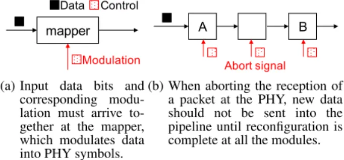
Figure 3: The problem of synchronization between control and data when reconfiguring a lower layer.
even though they are written in software, are often unmodifiable in practice.
Modifications of pipelines with static scheduling and static re-source allocation also cannot be undertaken without a deep under-standing of the system. Because it is practically impossible to doc-ument every assumption that goes into a high-performance imple-mentation, parallel software wireless platforms like SORA are hard to modify.
Until now, we have considered only the problem of executing a set of independent tasks on a multiplexed substrate. Achieving high performance in the context of communicating processes with shared data is even more difficult. Consider the relatively simple sub-component of an OFDM pipeline shown in Figure 2. If both the Encoder and the Interleaver execute sequentially, i.e., in one thread, then the correctness would not be affected by the changes in the code of either module. Pipeline scheduling, i.e., how often we switch from Encoder to Interleaver, is done statically and is part of the user code. Furthermore, information is usually passed from one module to another via shared memory using pointers. But if, for performance reasons, we want to execute the Encoder and the Interleaver in parallel, then accesses to the shared data structures (FIFO queues) have to be coordinated using locks. Since locks are expensive, software solutions minimize locking by doing coarse-grained synchronization.
For robust and modular software implementations, data should be passed from one module to another as messages via message-passing ports, rather than shared memory. This way, a module can modify the (local) data without having to lock it. The message-passing protocol needs to guarantee that the recipient has enough buffer before the producer sends data. The scheduling has to be dynamic enough to deal with variable processing times. Unfortu-nately, dynamic scheduling of modules to processors requires hibitively high communication and synchronization between pro-cessors under current multicore architectures.
4.2
Synchronizing Data and Control
Cross-layer protocol stacks require new ways of reconfiguring the lower layers at runtime, unlike standard commercial imple-mentations in which specific configurations and control paths are embedded in the design. The commands from the higher layer to trigger reconfiguration are usually referred to as “control” to distin-guish them from the actual data through the pipeline.
Consider the mapper module shown in Figure 3(a), which takes a data input (a group of bits to map into a PHY symbol) and a control input (the modulation that determines the mapping). For the map-per to function correctly, the modulation control should arrive at the same time as the data bits it applies to. Sometimes the reconfigura-tion affects several modules and has to affect them in a coordinated
mapper
Modulation
(a) The modulation con-trol and data bits ar-rive together along the same input at the map-per.
A
Abort response
B
Abort token
(b) Aborting a reception is accom-plished by forwarding an abort token along the datapath and withholding the data after the to-ken until reconfiguration is com-plete and a response is received. Figure 4: Examples illustrating data-driven control.
way. For example, the CMAP MAC protocol requires rapid switch-ing from receive to transmit, where the ongoswitch-ing reception must be aborted and all modules must prepare to transmit. For correct op-eration, transmit data should be sent along the pipeline only when all the modules have finished processing the control signal to abort and flush (Figure 3(b)).
Why is synchronization a hard problem when one wishes to add a new control? In typical hardware designs, the processing laten-cies of the different blocks are computed a priori and control is de-signed to be sent to each block just in time for the data; as a result, synchronization between the control and data is implicit. Although such designs can achieve high performance because one need not expend circuitry to handle synchronization, they are also hard to modify. Adding new control requires a careful understanding of the latencies of all the modules in the pipeline. Therefore, we use a different solution: data-driven control.
With data-driven control, messages between blocks contain both control information and the set of data values the control must op-erate on. Control tokens are embedded into the datapath along with the data, and are not modified by blocks that do not need to act on them as the message flows through the pipeline. The control information is stripped off when the message leaves the pipeline. Control tokens can be interspersed with data at any granularity, en-abling us to pass control with every bit or groups of bits, or per-packet. This approach incurs the overhead of extra hardware cir-cuitry to pass and identify control tokens through the datapath, but allows protocol designers to modify the structure of pipelines or refine any individual block easily without worrying about retiming the controls. Figure 4 shows an implementation of the examples in Figure 3 with data-driven control.
The concept of data-driven control is neither new to hardware
systems nor to software systems. For example, packet
trans-missions in wormhole networks use header-flits (controls) to re-serve buffers of each node along the paths until all the following body-flits (data) pass through that node. Another example is that Click [22] uses “packet annotations” to couple control and data to-gether. The notion is also used in SDR-based systems [18].
4.3
Passing Information to Higher Layers
Information from lower to higher layers may be passed at any granularity—once per bit, once per group of bits, or once per packet. As one may expect, passing new information along the pipeline faces an association problem similar to that between con-trol and data discussed in §4.2. Meeting stringent latency require-ments when passing up information is also a challenge because most network stacks assume that the higher layers act on data at the granularity of a frame at a time and only after the lower layer fin-ishes its processing for the entire frame. This coarse granularity of processing can be attributed to the prohibitive cost of fine-grained
Figure 5: Airblue hardware.
Soft Processor UART De vice In te rfa ce Radio DAC ADC Gain Circuit Baseband without Viterbi CSMA MAC Debug Interface PC FPGA 40 MHz 25 MHz 20 MHz Viterbi
Figure 6: AirBlue system architecture.
communications in software.
To pass information between layers in a timely manner, we pro-pose using a streaming interface between the layers. For example, when the MAC and PHY are both implemented in hardware, the PHY can send up bits to the MAC as they are decoded, instead of waiting for the complete frame to be received. This way, the MAC can receive and act on PHY information in a timely manner. Extra information along the streaming interface can be passed up using annotations. An annotation is additional information that is sent in-band along with the data. For example, when the PHY computes per-bit SoftPHY hints, the hints are pushed through the datapath along with the corresponding bits.
5.
THE AIRBLUE PLATFORM
Our platform presently consists of a MAC and PHY imple-mented on an FPGA. In the future, we plan to integrate these layers with the higher layers of the networking stack by either exposing the FPGA as a network device on a Linux PC or by implementing the higher layers in software on the FPGA. The Airblue MAC and PHY are both highly configurable and easy to modify, while run-ning at speeds comparable to commodity 802.11 hardware. We achieve these properties by rigorously following the two design principles, latency-insensitivity and data-driven control, described in the previous section. In this section, we first describe the hard-ware and softhard-ware components of Airblue and then present some performance results.
5.1
Airblue Hardware
Scrambler EncoderFEC Interleaver Mapper Pilot/GuardInsertion
IFFT/FFT
CP Insertion
Header
Decoder DecoderFEC InterleaverDe- MapperDe- EstimatorChannel Synchronizer TX Controller De-Scrambler ControllerRX Device Interface MAC
Baseband Processor
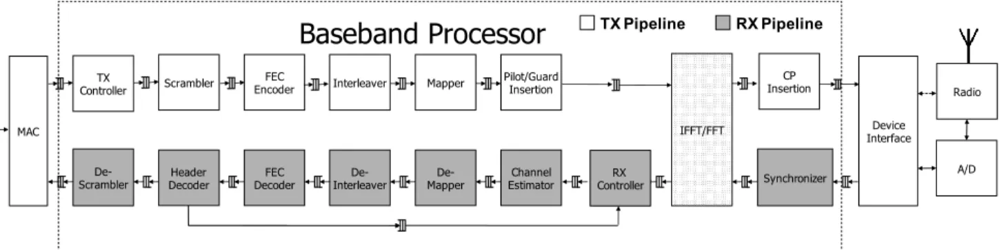
A/D Radio TX Pipeline RX PipelineFigure 7: OFDM baseband data flow in Airblue.
divided into three clock domains at 20 MHz, 25 MHz and 40 MHz respectively. The Device Interface, clocked at 20 MHz, provides a generic interface between the digital baseband and the RF front-end.
There are three blocks—the Baseband Processor, the MAC Unit and the Debug Interface—in the 25MHz clock domain. The
Base-band Processorimplements the PHY, converting digital bitstreams
to digital baseband signal during transmission and performing the inverse during reception. The MAC Unit controls when the
Base-band Processor can transmit or receive and implements an
ac-knowledgment protocol. The Debug Interface collects internal
state of other blocks and communicates this state to the host PC. The Soft Processor, running at 40 MHz, handles off-chip com-munications. In the future, we plan to use the Soft Processor to execute the software implementing the protocol layers above the MAC layer.
5.2
Baseband Processing on FPGA
Our baseband design (shown in Figure 7) uses a set of open-source modules from an OFDM workbench [28] that targets ASICs (not FPGAs). The library was written in Bluespec [29], a high-level design language that compiles into Verilog and can be further trans-lated into FPGA, ASIC or software implementations using other tools. All modules in the library are latency-insensitive.
In developing new protocols, users may have to modify the base-band modules in Airblue for the following reasons.
New features: A module may have to be modified to provide ad-ditional features. Modifications can be as simple as exposing some internal state of a module to other modules, or can be substantial modifications needed to implement new algorithms like computa-tion of SoftPHY hints (see §6.2).
Algorithmic modifications: Users may need to replace under-performing algorithms with more sophisticated ones. For exam-ple, the channel estimator in the original library turned out to be inadequate because it had never been tested with a real radio. It performed minimal phase tracking and no magnitude scaling, and had to be re-implemented using an algorithm that performed both. Performance tuning: A module may have to be modified to meet tighter throughput or latency constraints. Modifications normally involve exploiting more parallelism in an algorithm or improving data movement between modules. For example, we increased the per-cycle throughput of the original FEC Decoder twice to com-pensate for performance loss due to the lower clock frequency in FPGAs as compared to ASICs.
FPGA-specific optimizations: Some hardware structures targeted for ASIC implementations do not map well onto the FPGAs and
have to be modified to meet resource usage and timing require-ments. A typical example involves mapping register banks onto more dense SRAM-like resources. Conversely, the FPGA contains primitive resources, like multipliers, that enable the development of more robust and efficient algorithms.
5.3
Hardware Streaming MAC
The MAC is responsible for determining when the baseband sends or receives data. A typical MAC transmits frames received from the baseband, and reacts on receiving a frame by, say, sending an ACK back to the source.
Airblue’s MAC has two important properties that enable it to support a larger range of protocols than traditional MACs. First, the MAC is implemented in hardware with dedicated low-latency chan-nels to the baseband. This approach allows the MAC and the base-band to communicate large amount of data back and forth with tight latency. Second, it communicates with the baseband in a streaming manner, i.e., at the granularity of bytes instead of frames, enabling the MAC to start processing data from the baseband as soon as it is decoded. These two properties are necessary for the implementa-tion of cross-layer protocols that require the MAC and the baseband to frequently communicate with each other in a timely manner.
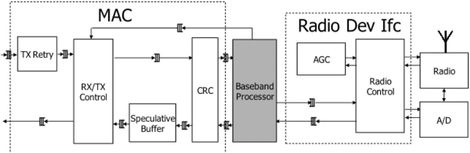
The architectures of the MACs can differ vastly depending on their access policies. For example, a MAC implementing CSMA will look completely different from a MAC implementing time division multiple access (TDMA). Airblue provides an 802.11-compliant CSMA MAC, as shown in Figure 8, that is modular enough to facilitate the implementation of derivative MAC proto-cols.
5.4
Radio Device Interface
To send and receive on-air signals, the baseband must commu-nicate with external devices like DACs, ADCs, gain circuits (see Figure 8). A challenging implementation problem is that many of these components are latency-sensitive. For example, if we change the gain, it takes a certain number of cycles before the correct gain is reflected in the incoming samples. To make matters worse, com-ponents implementing the same functions from different vendors have different timing characteristics. To keep the baseband flexible, we abstract the physical platform as a pair of bidirectional FIFOs to which the baseband can connect. From the baseband’s perspective, the incoming FIFO provides radio samples from the physical radio receiver and the outgoing FIFO sends samples to the physical radio transmitter.
Radio Control
Radio Dev Ifc
AGC Radio Speculative Buffer
MAC
TX Retry CRC RX/TX Control Baseband Processor A/DFigure 8: AirBlue’s MAC and Radio Device Interface. Our MAC consists of (i) RX/TX Control, which handles the 802.11 transmission control protocol, including packet acknowledgments and inter-frame timings; (ii) TX Retry, which buffers the transmitted packet until it is acknowledged; (iii) CRC, which handles CRC checksums of outgoing and incoming packets; and (iv) Speculative Buffer, which stores incoming packets until their CRC checks pass. Radio Device Interface consists of (i) Automatic Gain Control (AGC), which ensures received signals cover the full dynamic range of the ADC; and (ii) Radio Control, which configures the DAC, ADC, and RF circuits. 1.0E-08 1.0E-07 1.0E-06 1.0E-05 1.0E-04 1.0E-03 1.0E-02 1.0E-01 0 2 4 6 8 10 12 14 16 18 20 SNR (dB) BER Theoretical Measured
Figure 9: BER vs. SINR for 12 Mbps.
Airblue has been developed using Intel’s architect’s workbench (AWB), an open source design management tool [30]. AWB pro-vides a plug-n-play environment with a graphical interface for configuring, building, and running FPGA/software co-designs. It allows users to pick the implementation of each module in the pipeline from a list of valid implementations. AWB also facilitates the debug process because any system-level testbench can be used to test new modules by mixing-and-matching different implemen-tations of other modules. This methodology has been shown to be effective in producing new designs rapidly [31].
While on-air operation is the end goal of Airblue, simulation is crucial to evaluate and debug the implementation. Airblue provides a synthetic channel simulator for this purpose. Users can connect multiple transceivers to the channel simulator and simulate AWGN and fading environments. To accelerate long testbenches that in-volve millions of packets, part of the design itself can be compiled and run on FPGA, which effectively turns Airblue into a hardware/-software co-emulation platform.
5.6
Baseline Performance
We have implemented an 802.11g transceiver capable of sending data at the 6, 9, 12, 18, and 24 Mbps bit rates. We have also imple-mented various cross-layer mechanisms on Airblue, as described in §6. 0 5 10 15 20 25 128 256 512 1024 2048
Packet Size (Bytes)
Throughput (Mbps) 6 Mbps
9 Mbps 12 Mbps 18 Mbps
24 Mbps
Figure 10: Throughput with different packet sizes.
Airblue’s throughput and latency: To understand Airblue’s per-formance better, we evaluated the baseline 802.11 implementation using a pair of nodes, one configured as a transmitter and the other as a receiver. We used two topologies. To assess the SINR vs. BER (Bit-Error Rate) performance, we attached one node to a mo-bile platform and wheeled it around to vary the SINR. For all other throughput experiments, we fixed the nodes at a distance of 1 m. All experiments were performed in an RF-noisy office environ-ment.
Figure 9 shows the SINR vs. BER plot for the 12 Mbps data rate. Each point in the graph represents the BER and the SINR values of 1000 temporally contiguous packets. We also plot the theoretical BER versus SINR values, which we computed using MATLAB’s implementation of an optimum synchronizer, channel estimator, PSK/QAM demodulator, and Viterbi decoder. As seen from Figure 9, the SINR versus BER of the receiver follows the general exponential trend predicted by the theoretical model. Our measured performance is worse than the theoretical value by a few
dB. For example, at a BER of 10−4, the receiver’s performance is
worse by around 6 dB. Other data rates exhibited similar SINR vs. BER behavior.
We also measured Airblue’s throughput at different packet sizes. Figure 10 plots the receiver throughput as a function of packet size, at bit-rates up to 24 Mbps. The measured SINR for the environment
Module LoC Logic Regs RAM DSP Elms FFT 1051 5577 8530 32 32 Receiver 4833 29622 22921 99 89 Synchronizer 1561 8958 7442 72 66 Channel Est. 762 4926 4709 25 23 Viterbi 1070 3361 2756 0 0 Demapper 276 9527 1646 0 0 Deinterleaver 97 2358 2071 0 0 Transmitter 1167 9348 7487 0 0 Cyclic Prefix 165 1064 2756 0 0 Pilot 95 2864 2805 0 0 Mapper 159 2201 1401 0 0 Interleaver 176 863 681 0 0 MAC 2022 2139 1693 0 0 Device I/F. 1761 3321 2756 0 0 System Total 17250 54320 43776 142 123
Figure 11: Lines of code (LoC) and synthesis results of our 802.11a/g transceiver: the physical implementation used on the FPGA was obtained using Synplicity Synplify Pro 9.4 for syn-thesis and Altera Quartus Fitter 8.0 for place and route. These results exclude support circuitry like the soft processor.
in which this experiment was run was 16 dB. So, the BER at all
bit-rates was less than 10−6 (Figure 9). For all bit-rates, we achieve
the maximum throughput when transmitting large packets, as ex-pected. The throughput decreases gradually for smaller packets, as the preamble and packet header overheads increase. Our proto-type is able to meet various 802.11g timing specifications like turn-ing around from receivturn-ing a packet to transmittturn-ing an ACK within
25 µs2. On average, the power consumption of the whole platform
is 5 Watts throughout the experiment.
Program size: The total number of lines of Bluespec source code in our implementation is 17,250. Of this, 19.1% (3,288 lines) pro-vides the arithmetic library used across the design, 40.9% (7,051 lines) implements various parameterized modules in the baseband PHY, 10.2% (1,761 lines) implements the device interface that con-trols the RF front-end, and 11.7% (2,022 lines) implements the MAC. The remaining 18.1% (3,128 lines) describes the top-level of our 802.11 design by instantiating the modules with the right parameters and connecting them together. Compiling our code with the Bluespec compiler results in 202,672 lines of RTL Ver-ilog, which is more than 10 times the size of our source code. Synthesis results: Synthesis results for our transceiver are pre-sented in Figure 11. The transmitter is smaller than the receiver, because more complex algorithms are employed by the receiver to combat channel distortions. The synchronizer and the channel es-timator are two of the most complex blocks in the receiver (loosely reflected by the lines of code), although neither is the largest block in terms of logic elements. These blocks would have used a lot more resources if there were no built-in multiplier units in the FPGA.
Overhead of latency-insensitive designs: We quantified the over-head of latency-insensitive (LI) designs due to extra buffering and control logic. For this purpose, we rewrote the Channel Estimator module in the baseband PHY in a latency-sensitive (LS) manner using registers only. The LS design operates iteratively over its
in-2802.11g requires that the ACK is transmitted within a slot time
(9 µs) after the SIFS duration (16 µs).
Hardware Resource Latency-
Latency-sensitive insensitive
Logic Elements 5137 5438 (5.9%)
Storage Elements 2356 2429 (3.1%)
Figure 12: Comparing the cost of sensitive vs.
latency-insensitive implementations of the Channel Estimator. The
numbers in parentheses show the overhead percentage in-curred by the latency-insensitive design.
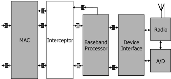
Baseband Processor Interceptor Device Interface A/D Radio MAC
Figure 13: An interceptor module in the MAC to enable easy modifications to the standard CSMA MAC.
put and output buffers, and assumes that adjacent modules sample those registers at the appropriate clock cycles. We picked this block for evaluation because its ratio of computation elements to storage elements is representative of other blocks in our design. Figure 12 shows that the LI design requires 5.9% more logic elements for the control logic of the FIFOs and 3.1% more storage elements to keep track of the occupancy of the FIFOs than the LS design. We consider this overhead to be quite acceptable for the ease of adding new functionality.
6.
EXPERIMENTS WITH AIRBLUE
In this section, we show how one can modify the MAC and PHY in Airblue to implement mechanisms that are useful for cross-layer protocols. The experiments below will demonstrate that Airblue provides both flexibility (comparable to a full software radio) and high performance (comparable to a hardware implementation). We target two relatively new, promising protocols proposed in the wire-less community: CMAP [3] and SoftRate [6]. We chose these pro-tocols because they have not been demonstrated in a high perfor-mance implementation, and because they cover a broad range of modifications required by cross-layer protocols. The main results in this section are summarized in Figure 14.
6.1
Sending Per-packet Feedback
We modify Airblue to send per-packet feedback from the re-ceiver PHY to the rere-ceiver MAC, and subsequently to the MAC layer at another node via the link-layer ACK frame. This mech-anism is useful for a variety of cross-layer MAC protocols, e.g., to send SNR or BER estimates for bit rate adaptation [24, 6]. We consider the specific example of sending the sum of SoftPHY hints (described in §6.2) as channel quality feedback, but the results de-scribed here broadly apply to sending other types of feedback as well.
The streaming interface between the PHY and the MAC deliv-ers SoftPHY hints and data bits to the MAC as they are decoded at the PHY. We add a new module to the MAC, called the intercep-tor, which sits between the baseband PHY and the CSMA MAC, as
Section Experiment Results
§6.1 Sending per-packet
feed-back.
Modified to generate link-layer ACK with channel quality feedback in 22.12 µs, meeting 802.11a timing requirement, in 20 lines of code.
§6.2 Computing and exporting
SoftPHY hints.
Replaced the Viterbi decoder with the soft output BCJR decoder that computes SoftPHY hints. This modification increases the receiver pipeline processing latency from 8.28 µs to 16.36 µs, but does not affect throughput. The latency-insensitive nature of the design ensures that the modifications are limited to the modules that compute and export SoftPHY hints.
§6.3 Decoding MAC header
during reception.
MAC-layer information starts streaming up to the MAC in 16.36 µs after transmission. Implemented in 43 lines of code.
§6.4 Runtime reconfigurations
through interrupts.
The MAC can interrupt and reconfigure the receiver pipeline in 11.12 µs. Implemented in 115 lines of code.
Figure 14: Experiments to implement cross-layer mechanisms with Airblue in §6. Most timing results presented are within the typical ranges expected in wireless standards like 802.11, making Airblue suitable for running realistic experiments. Moreover, all modifications except the implementation of SoftPHY hints are less than 1% of the project’s code base, signifying the flexibility of the platform.
Scrble FECEnc Intr Map InsPlt
FFT IFFT CP Ins Hdr Dec FEC Dec De-Intr De-Map Ch Est Sync TX Ctrl De-Scrble RX Ctrl Device Ifc MAC Baseband Processor A/D Radio Header
Decoder DecoderFEC
De-Scrambler
BCJR instead of Viterbi
SoftPHY hints passing
Figure 15: Modifications to the baseband PHY pipeline to com-pute and export SoftPHY hints.
shown in Figure 13. The interceptor provides a composable func-tionality to the MAC, by augmenting its function without requir-ing modification to the MAC itself. In this case, the interceptor snoops the data exchanged between the PHY and the MAC, com-puting the running sum of the per-bit SoftPHY hints exposed by the PHY in the same clock cycle that they arrive at the MAC. The final feedback is ready 16.32 µs after the packet transmission completes, the receiver pipeline processing latency when computing SoftPHY hints (see §6.2).
After the feedback is ready, it takes the MAC a further 3 µs to check the CRC on the packet and decide whether to send the link-layer ACK or not. If the MAC decides to send an ACK frame, the interceptor modifies the initial ACK frame, embedding feedback in the payload of the ACK as the ACK streams through the interceptor. This operation has no impact on the ACK latency. Finally, it takes the PHY transmitter another 2.8 µs to transmit the first OFDM sym-bol over the air after it receives the transmit request, for a total of 22.12 µs (16.32 + 3 + 2.8) to send a link-layer ACK embedding feedback. To put this delay in perspective, 802.11a stipulates that the link-layer ACK must be transmitted within a slot time (9 µs) af-ter the SIFS duration (16 µs), and our implementation comfortably meets this requirement.
All of the changes described above to the interceptor were per-formed in under 20 lines of code. The latency-insensitive nature of
Figure 16: SoftPHY hints of a 64-byte packet, and the positions of bit errors.
Airblue allows protocol designers to easily implement extensions to the 802.11 link layer using the interceptor module without delv-ing into the details of the original MAC implementation. Note that sending variable per-packet feedback in the link-layer ACK while meeting microsecond timing constraints is practically impossible to do in software-only network stacks such as SORA [15], which require at least many tens of microseconds to pass information be-tween the software MAC and the hardware radio front-end.
6.2
Computing SoftPHY Hints
We now describe how we modify the PHY in Airblue to compute SoftPHY hints, a mechanism used by some cross-layer protocols discussed in §3. This experiment illustrates the ease with which one can modify the processing pipeline of a layer in Airblue to add new functionality. We use a recently proposed technique [6] to compute SoftPHY hints: the log likelihood ratio (LLR) of a decoded bit being 1 or 0. This ratio increases with the probability that the bit has been decoded correctly.
The implementation of Airblue described in §5 uses a hard out-put Viterbi algorithm that only comout-putes the outout-put bits in a packet and not the LLRs. We replaced this decoder with a modified imple-mentation of the BCJR algorithm [32], capable of computing LLRs for each output bit, as shown in Figure 15. Figure 16 shows the SoftPHY hints computed from our decoder for a 64-byte packet at
the 6 Mbps rate, along with the positions of bit errors. One can see from the figure that low SoftPHY hints are strongly correlated with bit errors, demonstrating the correctness of our implementation.
We implemented the new decoder in 815 lines of new code, reusing several components from our Viterbi implementation. Because BCJR examines multiple backwards paths through the packet, the BCJR decoder has a longer pipeline latency than the Viterbi decoder, increasing our receiver pipeline processing latency from 8.28 µs to 16.36 µs, equivalent to an addition of 202 cycles at the 25 MHz baseband clock. However, this large change in la-tency of decoder did not affect the correctness of any other module in the pipeline, due to the latency-insensitive nature of our design. Although the processing latency increases due to SoftPHY compu-tation, the throughput of the PHY pipeline is unaffected because both decoders are capable of decoding 1 bit per cycle.
To export SoftPHY hints from the PHY to the MAC, we pass the hints along with the data by simply extending the data types of the interfaces between the modules downstream to the decoder to hold a 9-bit SoftPHY hint in addition to the data bit. This implementa-tion required changing 132 lines of code in the Header Decoder and Descrambler, as shown in Figure 15. Note that our implementation requires the communication bandwidth between the PHY and the MAC to be widened from 8 bits to 80 bits per cycle at 25 MHz. This is both reasonable and easy to implement because both the PHY and the MAC are implemented in hardware, which gives us flex-ibility to adjust the communication width to meet the bandwidth requirement. Had the MAC been implemented in software, this modification may have been been impossible if there were insuffi-cient communication bandwidth between the MAC and the PHY.
6.3
Decoding MAC Header During Packet
Reception
We saw in §3 that some cross-layer protocols like ZigZag and CMAP depend on knowing the MAC-layer source and destination addresses before the packet reception completes. We now illustrate the usefulness of our streaming MAC-PHY interface in exchanging such information quickly between the two layers.
802.11 packets typically consist of two headers, one for the MAC and one for the PHY. While receiving samples, the PHY must first decode its header to know which modulation and coding to use to decode the MAC header, then reconfigure the pipeline accordingly before the MAC header can be decoded. To avoid this additional delay of reconfiguring the pipeline before MAC-layer information can be passed up, we modify the packet format in our implemen-tation to send the time-critical portions of the MAC header at the
lowest bit rate just after the PHY header,3and the rest of the MAC
header at the higher payload rate. Note that sending the MAC-layer information at the lowest rate has the beneficial effect of increasing its reliability, thereby improving protocol performance. We imple-mented this mechanism by modifying just 43 lines of code in the
TX Controllerand Header Decoder modules in Figure 7 and the
Interceptormodule in Figure 13. In the new implementation, the
streaming interface at the PHY now passes up this portion of the MAC header in the same clock cycle that it is decoded. Therefore, the MAC can have the information it needs in 16.36 µs after packet reception starts — the receiver pipeline processing latency.
If one were to transmit the entire MAC header at the payload rate, then the MAC header would incur an additional latency of 11.8 µs, due to the additive latency of the PHY header decoder. Even this larger delay is small compared to the typical packet duration and
3
We transmit the 8 LSBs of the source and destination MAC ad-dresses and some parity bits in 2 OFDM symbols at the 6 Mbps base rate.
dwarfs the latency of passing information from hardware PHY to a software MAC.
6.4
Runtime Reconfiguration through
Inter-rupts
In this experiment, we measure the latency of reconfiguring the PHY to abort ongoing reception and switch to transmit mode. This mechanism is useful in CMAP, where the MAC must first receive the headers of the ongoing transmission, and then switch to transmit mode if its pending transmission does not conflict with the ongoing transmission. This experiment shows that Airblue allows higher layers to interrupt and reconfigure lower layers at runtime with very small delays.
We implemented the reconfiguration in this experiment using the request-response mechanism for performing coordinated reconfig-urations (§4.2). The Interceptor in the MAC first sends an abort request to the head of the receiver pipeline (RX Controller in Fig-ure 7). The controller then injects a special “abort token” into the pipeline and discards the remaining received data. Every module that receives the token flushes the state of the packet it was receiv-ing before. When the abort token reaches the end of the pipeline, the RX Controller sends a response to the Interceptor to indicate the completion of the abort. By resetting the state of the receiver pipeline, the correctness of future receptions is guaranteed. It is then safe for the MAC to initiate a new transmission.
Implementing the abort mechanism described above required changing 115 lines of code in the controller at the head of the pipeline, and did not require modifications to any other modules in the baseband PHY. The simplicity of this modification was the re-sult of our stream control mechanism in the pipeline — the pipeline modules expect a control token which demarcates the tail of the packet. We inject an abort token by sending a tail of packet control token.
The measured delay between the abort request and response at the MAC is equal to the time it takes for the abort token to travel along the pipeline from the RX Controller to the end, which is equal to 3.04 µs when using the Viterbi decoder and 11.12 µs when using the BCJR decoder. These latencies could be improved by reimple-menting the decoder modules to support a faster flush. Once again, we note that such quick reconfigurations of the PHY by the MAC cannot be performed if either the MAC or the PHY is implemented in software.
7.
DISCUSSION
In the previous section, we showed that novel wireless protocols can be implemented within the Airblue framework. However, Air-blue is not amenable to implementing all wireless protocols. By nature, FPGA implementations trade some performance for recon-figurability. As a result, an FPGA implementation will not perform as well as an ASIC implementation. Although we are confident that Airblue can run recently deployed wireless protocols like 802.11n with some augmentation, proposed protocols operating at above 10 Gbps will probably be out of reach of the FPGAs for the foresee-able future.
Airblue is a predominately hardware system. Designing high-performance hardware for a complicated function requires devel-opers to manually extract the parallelism existing in the underlying algorithm and then express it in a parallel hardware language. Air-blue does not free developers from this effort. Therefore, designing high-performance blocks in the PHY, like the BCJR decoder, is still a challenge in Airblue. However, we believe that our architecture is considerably easier to modify than other experimental wireless systems. For less parallel blocks, like the MAC, modifications are
more straightforward because they approach sequential program-ming.
8.
CONCLUSION
Cross-layer protocols require new features and functions in var-ious layers of the networking stack, a systematic way of passing additional information from lower layers to higher layers, and a fast way of controlling lower layers from higher layers. A develop-ment platform is not suitable for cross-layer protocol experidevelop-menta- experimenta-tion unless changes to the base protocols to implement such mech-anisms can be made easily. In this paper, we have discussed why the base protocols must be implemented in a latency-insensitive manner and must pass control in a data-driven manner to be modi-fiable by others. We have built a wireless experimentation platform called Airblue, which adheres to these design principles. In con-trast, current platforms like SORA and WARP do not follow these design principles, and hence, are difficult to use for cross-layer ex-periments.
Through the implementation of a variety of relatively complex protocol changes, we have demonstrated that Airblue is easy to modify and that, when modified, it meets the performance require-ments of current wireless protocols. In particular, we can easily modify the platform to send per-packet feedback, implement new decoding algorithms, and perform runtime reconfigurations of the pipeline, all while meeting 802.11 timing requirements. We be-lieve that such changes cannot be done as concisely on any existing platform. We are currently developing the next generation Airblue platform featuring a larger FPGA with MIMO support.
Acknowledgments
We thank John Ankcorn, Jamey Hicks, and Gopal Raghavan at the Nokia Research Center for their guidance, Quentin Smith and Ra-makrishna Gummadi at MIT for assistance in implementation, and Nabeel Ahmed at MIT and Kirtika Ruchandani of IIT Madras for their helpful comments. This project is funded by NSF under grants CNS-0721702, CCF-0541164, and CCF-0811696, and was previ-ously supported in part by Nokia.
9.
REFERENCES
[1] D. Halperin, T. Anderson, and D. Wetherall, “Taking the Sting out of Carrier Sense: Interference Cancellation for Wireless LANs,” in MobiCom’08, (San Francisco, CA), 2008.
[2] S. Gollakota and D. Katabi, “ZigZag decoding: Combating hidden terminals in wireless networks,” in SIGCOMM’08, (Seattle, WA), 2008.
[3] M. Vutukuru, K. Jamieson, and H. Balakrishnan, “Harnessing Exposed Terminals in Wireless Networks,” in NSDI’08.
[4] K. Jamieson and H. Balakrishnan, “PPR: Partial Packet Recovery for Wireless Networks,” in SIGCOMM’07.
[5] K. Jamieson, The SoftPHY Abstraction: from Packets to Symbols in Wireless Network Design. PhD thesis, MIT, Cambridge, MA, 2008. [6] M. Vutukuru, H. Balakrishnan, and K. Jamieson, “Cross-Layer
Wireless Bit Rate Adaptation,” in SIGCOMM’09.
[7] T. Moscibroda, R. Chandra, Y. Wu, S. Sengupta, and P. Bahl, “Load-aware spectrum distribution in wireless LANs,” in IEEE ICNP, 2008.
[8] S. Katti, S. Gollakota, and D. Katabi, “Embracing wireless interference: analog network coding,” in SIGCOMM’07, (Kyoto, Japan), 2007.
[9] S. Katti, D. Katabi, H. Balakrishnan, and M. Medard, “Symbol-Level Network Coding for Wireless Mesh Networks,” in SIGCOMM’08, (Seattle, WA), 2008.
[10] R. Gummadi, R. Patra, H. Balakrishnan, and E. Brewer, “Interference avoidance and control,” in Hotnets-VII, (Calgary, Canada), 2008.
[11] R. Gummadi and H. Balakrishnan, “Wireless Networks Should Spread Spectrum Based On Demands,” in Hotnets-VII, (Calgary, Canada), 2008.
[12] H. Rahul, N. Kushman, D. Katabi, C. Sodini, and F. Edalat, “Learning to share: narrowband-friendly wideband networks,” in SIGCOMM’08, (Seattle, WA, USA), 2008.
[13] “The GNURadio Software Radio.” http://gnuradio.org/trac.
[14] “Rice university wireless open-access research platform (WARP).” http://warp.rice.edu.
[15] K. Tan, J. Zhang, J. Fang, H. Liu, Y. Ye, S. Wang, Y. Zhang, H. Wu, W. Wang, and G. M. Voelker, “Sora: High Performance Software Radio Using General Purpose Multi-core Processors,” in NSDI’09, (Boston, MA), 2009.
[16] “Vanu software radio.” http://www.vanu.com.
[17] K. Tan, H. Liu, J. Fang, W. Wang, J. Zhang, M. Chen, and G. M. Voelker, “SAM: Enabling Practical Spatial Multiple Access in Wireless LAN,” in MOBICOM’09.
[18] G. Nychis, T. Hottelier, Z. Yang, S. Seshan, and P. Steenkiste, “Enabling MAC Protocol Implementations on Software-defined Radios,” in NSDI’09, (Boston, MA), 2009.
[19] Xilinx System Generator. http://www.xilinx.com/ise/ optionalprod/systemgenerator.htm.
[20] Altera DSP Builder.
http://www.altera.com/products/prd-index.html. [21] Synplicity Synplify DSP. http:
//www.synplicity.com/products/synplifydsp/. [22] E. Kohler, R. Morris, B. Chen, J. Jannotti, and M. F. Kaashoek, “The
Click Modular Router,” ACM TCS, vol. 18, no. 3, 2000. [23] W. Ji, Y. Chen, M. Chen, and Y. Kang, “Unequal error protection
based on objective video evaluation model,” in MobiMedia’07, (Nafpaktos, Greece), 2007.
[24] G. Holland, N. Vaidya, and P. Bahl, “A Rate-Adaptive MAC Protocol for Multihop Wireless Networks,” in MOBICOM’01, (Rome, Italy), 2001.
[25] S. Sen, N. Santhapuri, R. R. Choudhury, and S. Nelakuditi, “CBAR: Constellation Based Rate Adaptation in Wireless Networks,” in NSDI’10, (San Jose, CA), 2010.
[26] H. Rahul, F. Edalat, D. Katabi, and C. Sodini, “Frequency-Aware Rate Adaptation and MAC Protocols,” in MobiCom’09, (Beijing, China), 2009.
[27] R. Chandra, R. Mahajan, T. Moscibroda, R. Raghavendra, and P. Bahl, “A case for adapting channel width in wireless networks,” in SIGCOMM’08, (Seattle, WA), 2008.
[28] M. C. Ng, M. Vijayaraghavan, G. Raghavan, N. Dave, J. Hicks, and Arvind, “From WiFI to WiMAX: Techniques for IP Reuse Across Different OFDM Protocols,” in MEMOCODE’07.
[29] Bluespec Inc. http://www.bluespec.com.
[30] “Architect’s Workbench.” http://asim.csail.mit.edu/ redmine/projects/show/awb.
[31] N. Dave, M. C. Ng, M. Pellauer, and Arvind, “Modular Refinement and Unit Testing,” in MEMOCODE’10.
[32] L. Bahl, J. Cocke, F. Jelinek, and J. Raviv, “Optimal decoding of linear codes for minimizing symbol error rate,” IEEE TIT, vol. 20, no. 2, 1974.