Analysis and Restoration of a 1960s era Vacuum Tube AM-FM Reflex Receiver By
Adam J. Golden
Submitted to the Department of Electrical Engineering and Computer Science in Partial Fulfillment of the Requirements for the Degree of
Master of Engineering in Electrical Engineering and Computer Science at the Massachusetts Institute of Technology
August 6, 2004
F
4Copyright 2004 Adam J. Golden. All rights reserved. The author hereby grants to M.I.T. permission to reproduce and
distribute publicly paper and electronic copies of this thesis and to grant others the right to do so.
MASSACHUSETTS INSTITUTE OF TECHNOLOGY
JUL
1 8
2005
LIBRARIES
Author Certifiec D)yiuIxuscoe
'ECS y4sor Accepted by_ ATnlur %-. SmithAnalysis and Restoration of a 1960s era Vacuum Tube AM-FM Reflex Receiver By
Adam J. Golden Submitted to the
Department of Electrical Engineering and Computer Science August 6, 2004
In Partial Fulfillment of the Requirements for the Degree of Master of Engineering in Electrical Engineering and Computer Science
ABSTRACT
This thesis details the analysis, restoration, and evaluation of a 1960s era vacuum tube AM-FM reflex receiver. External influences such as tax laws necessitated clever designs to minimize the use of expensive vacuum tubes in radios. The thesis work yielded a thorough description of the circuits, the successful restoration of the radio to nominal operation, and concluded with a brief evaluation of the radio's operating characteristics.
Thesis Supervisor: Byron Roscoe
ACKNOWLEDGEMENTS
I want to thank everyone that I have worked with and learned from over the past 5 years here at MIT. Special thanks are due to Ron Roscoe, who has provided me with many opportunities and guidance. Whether it was some part time money grading papers, advising a thesis, or helping me with my 6.101 project he has always been there. The countless political debates and exchanges over the state of the world and American politics were also particularly rewarding, entertaining, and a welcome change from the daily grind of the uber-technical education and environment at MIT. Thanks also go out to Joe Sousa, who graciously offered time and effort on several days to help tackle this project. I also want to thank my parents and family a great deal for financing and encouraging me to take on MIT these past 5 years. Without this support network,
everything would have been unfathomably more difficult, and for all of their support I am eternally grateful.
TABLE OF CONTENTS
1. Introduction ... 9
1.1 Summary of Thesis Work 10
2. Analysis of Design...12
2.1 Review of Tube Operation 15
2.2 FM Operation 22
2.2.1 FM Front end 23
2.2.2 First IF Amplifier 25
2.2.3 Second IF Amplifier and Detector 27
2.3 AM Operation 29
2.3.1 AM Front end 30
2.3.2 IF Amplifier and Detector 31
2.4 Audio Output 32 2.5 Circuit Summary 33 3. R estoration ... 37 3.1 Restoration Plan 37 3.1.1 Mechanical Tests 37 3.1.2 Voltmeter Measurements 39
3.1.3 Vacuum Tube Tests 41
3.1.4 Replacing of Old Components 43
3.1.5 Signal Tracing 45 3.2 Restoration Summary 47 4. E valuation ... 49 4.1 Distortion 49 4.2 Bandwidth 51 4.3 Evaluation Summary 52 5. C onclusion... 54
6. Appendix A: Circuit Schematic...57 7. R eferences... 59
1. Introduction
Not even the Radio Engineer can escape the burdens of the Taxman. Any practicing engineer could easily describe hundreds of various factors that influence his designs. Obvious factors immediately come to mind: process technologies, materials,
environment, reliability, and costs, however, one not so obvious factor, taxation,
influenced 1950s and 1960s West German radio designs. Designers used many different strategies to maximize the usefulness of each tube in a design. One popular design was to use what is known as a "reflex" circuit. A reflex amplifier is a design that uses a vacuum tube or other linear amplifier with a large enough bandwidth to amplify multiple signals simultaneously at different frequencies without interference. Often this meant that radio designers could use one tube to amplify incoming RF signals and lower frequency IF or even audio signals at the same time [2]. This thesis project will explore in detail a receiver design from 1960s West Germany that incorporated reflex design.
1.1 Summary of Thesis Work
This thesis documents the analysis, restoration, and evaluation of a vacuum tube AM-FM reflex receiver. The first phase of this thesis was to compose a thorough analysis of the
radio's design. Analysis of the design began with a brief review of vacuum tube
technologies and design followed by an overall block diagram description and discussion of various signal paths in the radio. Next the analysis continued inside each of these functional blocks and examined the form and function of each passive component and active device. Finally, the analysis phase concluded with a unified explanation of the circuit design and operation incorporating the detailed functional blocks and simplified signal paths.
The second phase involved restoring the inoperable radio to working order. Leveraging the knowledge and insights gained in the analysis phase, the inoperable radio
was properly diagnosed and repaired. The restoration of any old electronic device requires careful inspection of the device coupled with a tedious attention to clues about the malfunction. One of the first tests performed was to remove and confirm that all the
vacuum tubes were still operating with sufficient gain and were not the fault source. After that, measuring voltage, current, and examining signals on an oscilloscope enabled a
quick determination of any continuity defects and helped determine if any of the old components simply outlived their operational lives. After restoring the radio it was then time to evaluate the radio.
The thesis work ended with a brief characterization of the restored radio. This phase began with some basic tests of radio receiver distortion and bandwidth. More
comprehensive testing and comparison with other radios of the era was not possible due to time constraints.
Completing this thesis yielded several rewards. First, it is important to revisit historical designs for knowledge, inspiration, and fun. Decoding the problems and solutions of past designs bolster one's ability to design new circuits. Second, the restoration phase provided valuable experience in practical diagnosis and repair of a malfunctioning circuit. This is a great educational complement to my highly structured coursework in that the problem and the solution are incompletely defined, more closely resembling real life engineering work. Finally, it is always a lot of fun to get out lab equipment and "play" with real hardware.
2. Analysis of Design
Analysis of any complicated system can often be as difficult as the original system design. This results for a number of reasons: different design techniques, strange
notation, or ingenious designs. Therefore, it is very important for anyone about to attempt an in depth analysis of a complex system to try to familiarize themselves with the tools and practices of the original design environment. The case is no different with this old German vacuum tube radio design. At first glance, this circuit appears intimidating, as much for the convoluted schematic (Full page schematic included in Appendix A) as for all the functionality contained in this 3 vacuum tube design. However, after making some translations of the terminology and identifying key components of the circuit, the schematic begins to feel less foreign and the circuit's functions slowly begin to emerge.
After resolving the initial confusion of a dual-language schematic that uses slightly different device symbols, the basic functions and signal path of the circuit were determined and located. The signal basically flows from left to right starting with the AM and FM antennas and ending with the speaker output, as seen in the schematic depicted below. There are three vacuum tubes representing the 5 active, or gain producing, devices in the signal path of the circuit. Two of the tubes have two separate amplifiers within the same glass envelope while the third tube is a standalone device. Examining the schematic in greater detail in the vicinity of the first two amplifiers, several tuned circuits can be identified by their characteristic combinations of capacitors and inductors. This portion of the circuit appears to be a couple of tuned gain stages and possibly a mixer, common elements in radio receiver circuits [4]. The middle tube is the standalone device and is
near several diodes and a couple more tuned circuits. This tube likely is involved in the detection or demodulation of the incoming amplified signals from the first stage. The last two amplifiers are easily recognized as an audio voltage amplifier and power amplifier output stage for driving the speaker.
EOX IS Ec 5
6 .oi M LEM 1 wil R~f Anllner toehlt ] P OT5GA
tt2 220 416FU 20741 9,S -ON, ON ERIL WN -R W
1
EKEG B
UH
{ A . 117F ECpe A0 r-1U W,2 U I . W-;F 277 W IIt F77r82Grndg chmaiThsognzttno h ici yWd 5C baiZlcsLhi untoswl emr
113
ill-i I . j - I2 kit7 2
7232 711.1
727 M'7.
2722727.71 S227277 77 72s724r~27727 till,2 7777
OIL2.2777 IT277S 7727777777 161.27772,777202222 IT*
777777 272 767727 ON,2. 77.72 777.77777777722771 in7.. ' 777772. , 7 2,.7 .77 . 77-7, 7777
97 1.- U"
UUJ~l~j 72.7677 777 ~ 7 .~Ilk2
GAME -046 -. 7777P- 2~J7277o
&10- 27 . M 77 27W 7 277 tor ."a 2.i 7kH 77~v = " * .7 7 7 . 77 5 77 7
C~IK ISISI WITH G(SAY.)71
AM/FM Supe IOOUIO1U12
SINA
CON AERIAL-72
,8Lit NO6 3
defined and examined in the more thorough analysis in the ensuing sections. For now we can label the rudimentary blocks based on their assumed functionality. Starting with the first device on the left and moving right: RF amplifier, Mixer/oscillator, ]IF
filter/amplifier, Audio voltage amplifier, and Power amplifier [1]. The significance, usage, and determination of these blocks will be described in greater detail in the analysis of the AM and FM operation respectively. Examination of the blocks of this circuit separately for each mode of operation, both AM and FM, will further clarify the analysis. Finally, it will be insightful to integrate all of the analysis from the two separate modes together to appreciate the resourcefulness of each component in the design.
Before delving deeper into the analysis of each of the blocks, it is necessary to provide a review of the operation of vacuum tubes that are used in this design. Most modem electrical engineering curricula focus on the ubiquitous transistor. The mere mention of vacuum tubes to any modem circuit designer is enough to draw confused looks and verbal barrages of how the older technology is inferior and archaic. However, the reality is that tubes continue to be used in niche modem designs, and their operating characteristics actually closely mimic those of the junction field-effect transistor (JFET).
A quick refresher on tubes will describe their basic operation, device types, and
illuminate several similarities that will enable the use of the transistor designs and intuitions, that are taught in modem classrooms, to facilitate the circuit analysis.
2.1 Review of Tube Operation
Once as ubiquitous as the transistor in electronic designs, vacuum tubes are now only found in a few highly specialized circuit applications [9]. Both devices allow the designer to use a small voltage to control a much larger current. The design and materials used to make transistors have enabled their rapid shrinking in both cost and size. The modern
BJT and then the MOSFET thus ended the reign of the vacuum tube as the amplifier of
choice for circuit designs.
Vacuum tubes, or thermionic valves, are arrangements of electrodes in a vacuum within an insulating, temperature-resistant envelope. Although the envelope is classically glass, power tubes often use ceramics, and military tubes often use glass-lined metal. Vacuum tubes resemble incandescent light bulbs, in that they have a filament sealed in a glass envelope, which has been evacuated of all air. When hot, the filament heats a piece of metal called a cathode, which releases electrons into the vacuum, a process known as thermionic emission. The resulting negatively charged cloud of electrons is called a space charge. These electrons are drawn to a positively charged metal plate, called simply the plate or the anode. This results in a current of electrons flowing from cathode to anode. Obviously this does not work in the opposite direction, because the anode is not heated. Therefore this device, a diode, conducts current in only one direction [5,9].
However, the addition of another electrode between the cathode and anode, or plate, yields a way to control the flow of current. Varying the voltage on this new electrode, or grid, controls the current flow from cathode to plate. The resulting current drawn by the grid is very small, the result of electrons intercepted by the tiny electrode in
the middle of the current flowing from cathode to plate. This three-element device is known as a triode, and is the simplest of vacuum tube amplifiers. It is roughly, functionally equivalent to a JFET, because only a tiny voltage is required to control a large current. Just as in transistor amplifier designs, these triodes have a linear operating range and must be biased properly, via a grid leak biasing resistor or other means, to ensure the greatest linear amplification range [5,9].
P'LA7E PLATE
CATHODE
FILAMENT C1#
Figure 3 Vacuum Tube Diode and Triode
When triodes were first used in radio transmitters and receivers, it was found that
they were often unstable and had a tendency to oscillate due to parasitic plate to grid capacitance. Many complex circuits were developed to reduce this problem, such as the Neutrodyne amplifier, but proved unsatisfactory over wide ranges of frequencies [2]. It was discovered that the addition of a second grid, located between the control grid and the plate, called a screen grid, could solve these problems. A positive voltage slightly lower than the plate voltage was applied to the screen grid, and it was bypassed for AC signals to ground with a capacitor. This arrangement acted as a shield decoupling the plate and the first grid, completely eliminating the oscillation problem and greatly reducing the parasitic capacitance [9]. The input capacitance to an amplifier sets the
dominant time constant that controls how much bandwidth the amplifier is useful over. As in transistor design, the input capacitance is effectively much higher in high gain
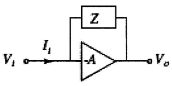
amplifiers due to what is known as the Miller effect. The parasitic capacitance at the input node is dominated by the grid-to-plate capacitance that is being Miller amplified. The Miller effect occurs whenever there is a device that connects the input and output of
a high voltage gain device. The effective capacitance seen is amplified because the voltage at both ends of the device move synchronously [6,10]. The miller effect, for a large inverting amplifier, therefore would reduce an inductive or resistive load by this
1+A factor or increase the capacitance by this factor, as described below in figure 4 and
5.
z0
Figure 4 Diagram for describing the Miller Effect
i
-
V1
1+A
Zl -Z
Zin ==1
,I1
1±+A
+
A
Figure 5 Equations for calculating the Miller effect on input impedance
Luckily, minimizing or eliminating the capacitance linking the input and output can neutralize this nasty effect. Often this is done in transistor design by utilizing what is known as a cascode design. The cascode uses a second transistor, in common-base/gate configuration, to buffer the output of the high voltage gain first transistor, usually a common-emitter/source stage, thus eliminating any possibly Miller multiplied capacitance [6]. The addition of the second grid here acts in much the same way, by providing an AC ground in between the input and output capacitances. This two-grid tube with the miller compensation is called a tetrode, meaning four active electrode device.
P'LA~PLAIT
HEAER HEATER
Figure 6 The tetrode and pentode
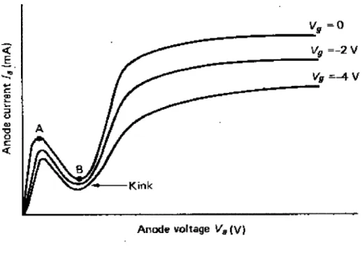
However the tetrode too had a problem, especially in higher-current applications. At high instantaneous plate currents, the plate became negative with respect to the screen
grid. The positive voltage on the screen grid accelerated the electrons, causing them to strike the anode hard enough to knock out secondary electrons that tended to be captured
by the screen grid, reducing the plate current and therefore the amplification of the circuit [9]. This effect, shown in figure 7, was sometimes called "tetrode kink".
Vg =0
Anode voltage V=(V)
Figure 7 I-V curve for tetrode demonstrating "tetrode kink"
Again the solution was to add another grid, called a suppressor grid. This third grid was biased at either ground or the cathode voltage. Its negative voltage, relative to the plate, electrostatically suppressed the secondary electrons by repelling them back toward the anode. This three-grid tube was called a pentode, meaning five electrodes. Tubes with 4, 5, 6, or 7 grids, called hexodes, heptodes, octodes, and nonodes, were
generally used for frequency conversion in superheterodyne receivers [5]. The additional grids sometimes acted as plates but often they were used as control grids with different
signals applied to each one. In combination with each other, they created a single, combined effect on the plate current and thus the signal output of the tube circuit.
E E C0 4 ~560 IbU 4 32LI
Plate volts
4OUFigure 8 I-V curve demonstrating the correction of the "tetrode kink" in the pentode
Of these, one of the most commonly used was the heptode, or pentagrid converter.
This tube was especially common in superheterodyne radio receivers. The popularity of this tube was that it could perform the role of local oscillator and mixer in one device. This tube was able to self oscillate at the local oscillator frequency and at the same time accept the incoming signal. The difference frequency was available at its plate. Although the pentagrid worked well in the presence of a strong or isolated signal, it did not work so well when it was desired to receive a weak signal that was close in frequency to a
stronger signal. The stronger signal tended to 'pull' the local oscillation such that the stronger signal was the only one that could be received. On the other hand, this 'pulling' of the oscillation provided a degree of automatic tuning. Although this tube contains 7
12 ~
I
___ __ep
MWPP
Ec,= 0
4 0
-~ ~ ~ ~~1 - tim"f.im -W- - - 1
electrodes and is thus technically a heptode, this device is usually referred to in technical literature as a pentagrid, to distinguish it from a true heptode [9]. The grid in the
oscillator circuit has to have a screen grid on either side to isolate it from the grid that carries the incoming signal. The remaining grid is the suppressor grid to combat secondary emission.
One final type of tube to discuss, the beam power tube, is usually a tetrode with the addition of beam forming electrodes, which take the place of the suppressor grid. These angled plates focus the electron stream onto certain spots on the plate that can withstand the heat generated by the impact of massive numbers of electrons, while also providing pentode behavior by suppressing secondary emissions. The positioning of the elements in a beam power tube use a design called critical-distance geometry, which minimizes the "tetrode kink", plate-grid capacitance, screen-grid current, and secondary emission effects from the plate, thus increasing power-conversion efficiency. The control grid and screen grid are also wound with the same pitch, or number of wires per inch. Aligning the grid wires also helps to reduce screen current, which represents wasted energy [9].
Now that we have reviewed the history and types of vacuum tubes, it will be useful to identify the usage and types of tubes in the radio design we are analyzing. There are three different vacuum tubes used in this design, two of which have two separate devices. These are identified in the circuit diagram by the names ECC85, EAF801, and
ECL86. The ECC85 is a dual triode tube, having two isolated, independent triodes. The EAF801 is a bit more complicated. It contains a regular pentode circuit and also a diode.
contains a normal triode device and a power beam pentode, each being independent devices. Having reviewed vacuum tube operation and identified the types of devices used in this design, its time to begin the in depth analysis of the circuit.
2.2 FM Operation
The FM operation of the radio utilizes a reflex superheterodyne design. Superheterodyne receivers "beat" or heterodyne a frequency from a local oscillator within the receiver with the incoming signal. The user tunes the radio by adjusting the set's oscillator frequency. This heterodyning (multiplying) produces a signal at the sum and difference of the two signal frequencies. The lower frequency typically is chosen as the IF, which is amplified and then demodulated or reduced to audio frequencies and output through a speaker.
Almost all receivers in use today utilize this method. The superheterodyne design is so universal in receivers because it reduces the performance required of the amplifier and filter components. By mixing the incoming radio signals and filtering out the resulting lower frequency IF, or intermediate frequency, the designer is able to save money and effort by building amplifiers and filters at this lower frequency rather than the higher frequency RF. Furthermore, by tuning the local oscillator, the IF is kept constant across the full spectrum of the AM or FM band. This allows for IF filters and amplifiers to be optimized for a single frequency.
aerial
fm loudspeaker
rf amplifier mixer If amplifier demodulator at voltage af power
amplifier amplifier
afC oscillator
Figure 9 Block diagram for FM receiver operation
The diagram above shows the basic elements of a single conversion
superheterodyne receiver. In practice not every design will have all these elements, nor does this convey the complexity of other designs, but the essential elements of a local oscillator and a mixer followed by a IF filter/amplifier are common to all
superheterodyne circuits. The analysis of the FM receiver circuitry for this radio has been divided into three sections encompassing all the functionality shown in the above
diagram from antenna to demodulation.
2.2.1 FM Front end
The FM front end consists of the antenna, a reflex amplifier used on both RF and IF signals, an oscillator, and a mixer. The signal comes in via the antenna into a tuned transformer, in parallel with the antenna and C301. The secondary of this transformer couples the RF into the cathode of the first triode. This triode is the reflex amplifier. This
amplifier, for the RF, is a common base/gate configuration from transistor design and in fact, this common grid amplifier works the same way. This arrangement is used for high frequency applications because the grid separates the input and output providing an intermediate ground for parasitic capacitances from input to output. This minimizes oscillations and parasitic capacitances and also presents low input impedance to the antenna. The combined result of these characteristics is a fair amount of gain for a large bandwidth. The amplified RF signal is then capacitively coupled from the first triode's plate to the second triode's grid through a tuned transformer, near the capacitors labeled C314, C315, and C316.
a
.1 'I st?3S4 454i rasi I 0~3 L ~b C 31 1 C3 Mof VF E Ilpf.. t 3 Is~~~~~~ rt SW 2JJ-1 A ! -#239________________________0 ______ I$P 5P 130 C 2 I A~ I I --JFigure 10 Circuit schematic of radio front-end with FM signal path highlighted
F1 7207-416 r - - - - j # SIM - 034 L 16 Nil a -P Ala I I VWMT Ivor
The second triode in the FM front end is a little bit more complicated to decipher its function. This is due to the large number of peripheral components and the presence of 2 tuned circuits, one each on the grid and plate. The two tuned circuits are identified for FM operation due to their relatively low valued capacitors in parallel with a pair of
center-tapped inductors, indicating that they are for use at higher frequencies, not AM frequencies. The tuned circuit attached to the second triode's grid, in parallel with C325 and C328, is the local oscillator feeding the grid simultaneously with the output from the RF amplifier, also coupled to the grid. The triode is being operated as a grounded cathode converter. The amplified RF from the FM antenna is applied on the grid with the tuning
signal from the local oscillator and these two signals combine on the triode's grid to modulate the output plate current of the converter at the expected sum and difference frequencies. The lower of these frequencies is 10.7 MHz and is the frequency used for the
IF in FM designs. A portion of this output signal is fed back to the local oscillator via a
capacitor, C 322, to the center tap of the oscillator's transformer to maintain stability. Finally, the output is traced through another tuned transformer, directly above C 308,
supplying the grid of the first triode.
2.2.2 First IF Amplifier
The first IF amplifier is a bit tricky to locate in this circuit and is responsible for the radio being dubbed a reflex receiver. In order to get the needed gain for proper FM reception, without having to pay for an additional tube, the designers utilized a reflex design. The first triode is being used as a common grid amplifier for the incoming RF, in the 88-108
MHz range. The FM IF frequency is 10.7 MHz and the designer realized that this was an order of magnitude lower in frequency and therefore could safely put the triode to use amplifying both signals simultaneously. Ideally, by superposition, the two separate signals should not interfere or modulate each other, and the amplifier will amplify both signals independently at the same time. However, this creates other possible problems because you now have to worry about arranging proper biasing levels for both
amplifications, setting the proper gains independently, and inevitably some parasitics such as crosstalk and cross-modulation.
Nevertheless, this triode amplifier doubles its usefulness in the FM design. The output of the triode converter is coupled onto its grid via a transformer tuned to the IF frequency, 10.7 MHz, and thus filtering out higher frequency and RF components. The grid input has a small inductor in parallel with the input resistor, R302, to help limit overloading of this stage. The inductor has a neutralizing effect in helping to ensure stability of the amplifier at this frequency, as the Miller capacitance on this stage should be quite significant.
This common-cathode amplifier characteristically provides significant voltage gain with the resulting output signal appearing on the same plate current as the amplified RF from the antenna. This problem is remedied in by having tuned transformers, near the sets of capacitors labeled C314, C315 and the other above C2 inside the F box on the schematic, directing each signal to its appropriate output source. In this case, the
amplified IF is then coupled to a final double-tuned transformer, of which the top tuned circuit is set to 10.7 MHz and feeds the second IF amplifier stage prior to reaching the FM detector.
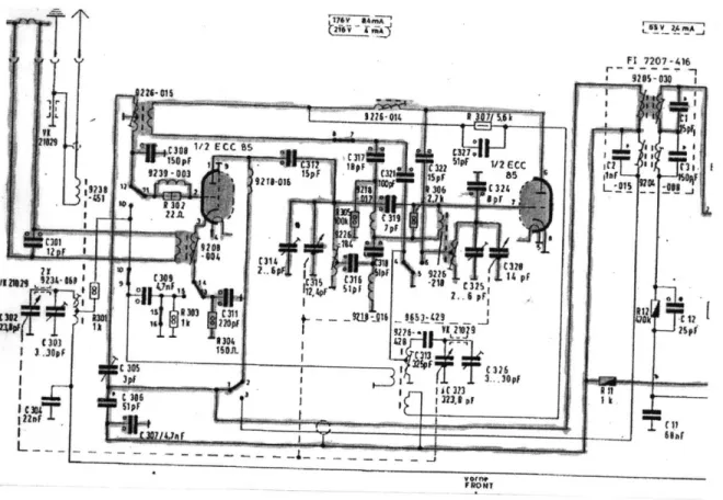
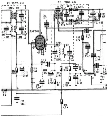
2.2.3 Second IF Amplifier and Detector
The output of the common cathode triode in the front end is coupled through a double-tuned transformer and passed on into the control grid of the pentode IF amplifier. The pentode, as mentioned in the tube review, maintains a high gain with relatively little miller capacitance due to the addition of two helper grids. The pentode is biased as a common cathode stage and it's amplified IF output appears at the plate. Here again, the circuit gets a bit tricky with the 10.7 IF signal being coupled through two tuned circuits to the FM detector circuitry.
FT 7207-416 9205 -030 t ts 3 laf 0S -015 08 r- 7207-417 EA ~1 1 n 7s~~
Figure 11 2nd IF amplifier and FM detector
The FM detector circuitry has a very characteristic appearance, featuring two oppositely wired diodes and a large capacitor bridging them. This is symbolic of what is known as a ratio detector. Ratio detectors are common in compact FM radio designs because they do not need a limiting stage, thus saving power and unneeded gain. Other FM detectors, such as phase detectors, require a high gain to "rail out" or limit the incoming FM signal in order to eliminate any residual amplitude modulation that could degrade the output audio. However the unique operation of the ratio detector eliminates most any effect of residual amplitude modulation that can corrupt the audio output.
R12 VOk F801, 5 '61 1. AA1 RMj/ 820L --I 39P
9
06 A1 R2/401 4( ?1829 lit n I i tp 2,*F C?3 7* t 11 0 E21nT
/k 7T2M
The ratio detector begins by coupling the IF signal in via the complicated
transformer located inside the dotted box labeled FIl. A transformer tuned to the center IF frequency, 10.7 MHz, is at the heart of the ratio detector. The ratio detector reproduces the modulation audio by generating a voltage in proportion to how far above or below resonance the tuned transformer of the ratio detector is. Following this final step the
output audio is low-pass filtered by a few capacitors and resistors, R19 and C18 and C19, on its way to the input of the audio portion of the circuit.
2.3 AM Operation
The AM operation of this radio receiver also utilizes a superheterodyne design as mentioned above. The characteristic elements of a superheterodyne design are all
apparent in the block diagram below. In fact, almost all the circuitry and functionality of an FM and AM receiver are identical before detection. The only real difference in
operation is that the IF frequency used for the AM receiver is lower and the bandwidth of the channels and the overall signal band are significantly smaller. One more difference is that the AM operation of the receiver does not utilize a reflex amplifier. The AM portion of this analysis has been similarly divided up into two sections representing the
aerial
am loudspeaker
rf filter mixer f amplfier j demodulator a! voltage at power
amplifier amplifier
oscillator agc
Figure 12 Block diagram for AM operation
2.3.1 AM Front end
AM signal path begins with the antenna feeding a tuned filtering transformer stage, to select the raw AM RF signal of interest. The selected station or channel is then fed into the grid of the first triode. The signal path for AM operation in the front end section has many differences compared with the FM operation, as shown in the graphic below. In AM operation, this amplifier is no longer required to perform double-duty reflex
amplification. Instead, this triode now operates as a triode mixer. The second triode used as a mixer in the FM design, is now operated as a tuned-grid oscillator, with the tuning provided from the tuned-circuit around capacitors C328 and C313. The local AM oscillator frequency is coupled in via the cathode of this triode and thus provides full modulation of the plate current at this frequency. The mixed, or beat, signal is then available as before at the plate of the first triode. This IF output is coupled to the pentode
IF amplifier via the same route as the FM IF, through the double tuned transformers
W 1 1 3 I'Ti -1 VA 003 ilpf i-004 r ~ 5 m~ p Z34 F1 7207-416 16k
Figure 13 Circuit schematic of radio front-end with AM signal path highlighted
2.3.2 IEF Amplifier and Detector
After passing through the double-tuned transformer housed in FI, the IF signal is then applied to the input control grid of the common-cathode pentode IF amplifier. This amplifier, as mentioned before in the FM discussion, provides a large amount of voltage gain with minimal input parasitic capacitances. The output amplified IF signal then passes through the first tuned transformer attached to the input of the ratio detector.
U e C 17 S:P F 1/ 2EM r93- i I* C32 I C--PF. * P 922 14 pF Sipi r 3 . 2 73 32 3 26of
F1 7707 -416 C c I ail R 12 C 1z -2 Spf Ft 7207-417
:0
+
t14 39I C, AA1 I 78k $ t1 1. -~I
A I6 4. kFigure 14 IF Amplifier and detector with AM signal path highlighted
couple of tuned transformers into the Pentode IF Amplifier. Pentode is common cathode for high gain and then this signal is coupled to the local diode for detection and low-pass filtered on way to audio stage input. R15 provides AGC control feeding back a dc voltage to the input grid of the IF amplifier stage and the 1st triode mixer.
2.4 Audio Output
All of the circuitry after the demodulation stage for AM and FM is used identically
during both modes of operation. This is because this section of the circuit deals
... ... AFS01 1S6k I C )b C
exclusively with audio signals. The audio output section of the circuit contains three main functional blocks, two of which, AF voltage amplifier and AF power amplifier, are shown individually in the overall AM and FM system block diagrams above. The three parts of this section that are described in further detail below are the tone and volume controls, the audio voltage amplifier, and the power amplifier driving the speaker.
112 ECL WL C31 ..... .. ... .... ... TioT 1/2l WEd L P 86l ECU ft4RO02 ~ t '05 -001 We W* 0 *.I U 105OZ bi 101V I *-- ' 4 -t3 T 1Z4j
Figure 15 Circuit schematic of the Audio Output section of radio
2.5 Summary of Circuit
In summary, we have analyzed this circuit under both AM and FM operations
independently, realizing that much of the circuitry required for these two different modes is identical. In particular, given that both the AM and FM front ends utilize a
superheterodyne design, the operation of the circuit in both modes from antenna through the pentode IF amplifier is functionally identical, aside from the difference in frequency
and bandwidth of the two IF frequencies used. The incorporation of the common circuitry for both designs was achieved via a combination of a clever switching network as well as using tuned transformers to ensure that the proper signal frequency is directed to the appropriate inputs and outputs.
The FM circuit had particularly interesting properties of being reflex and having 2
IF gain stages and a broadband RF amplifier. The FM section consisted of bringing in raw RF to a common grid amplifier. The amplified RF is then combined with the local oscillator signal on the grid of the second triode, being operated as a grounded cathode triode converter. This signal supplies the circuit with the reflex tag, by being coupled back through the grid of the first triode, this time as a common cathode amplifier at IF frequency, with the output being selected out by a double tuned transformer to the
pentode IF amplifier and the ratio detector. The ratio detector, common in FM designs, is unique for providing inherent limiting, negating the need for a separate pre-limiter stage to eliminate unwanted amplitude modulation on the FM signal.
The AM circuit was interesting because it began with a tuned transformer directly fed from the antenna tuned to the desired AM channel. This is in contrast to the
broadband RF amplifier used in the front of the FM circuit. This AM signal from the tuned antenna was then fed into the grid of the triode mixer, with the local oscillator signal, from the second triode, being coupled in via the cathode from a tickler coil. One other slight difference in the AM circuitry was the use of automatic gain control via R15 and R16. These two resistors provided a small voltage feedback to the IF amplifier stage to Used a simple diode am detection circuit tapping off the output signal again from a double-tuned transformer.
The audio section was nicely analyzed separately since it is utilized by both AM and FM modes identically. It only dealt with audio, and of all the circuitry on the schematic was the most straightforward to follow. It began by coupling in the audio signal from the pentode IF amplifier/detector stage into a set of potentiometers and
capacitors. These devices were acting as the tone and volume controls prior to feeding the audio voltage amplifier. This amplifier was simple, just a common cathode for high voltage gain, with output coupled directly into the beam power tube driving the speaker. This section of the circuit was somewhat interesting for feedback/filtering utilized to eliminate the 60 Hz hum that would have coupled through the beam power stage to the
speaker.
Overall, this was a challenging but interesting circuit to analyze. The design demonstrated a great deal of clarity and ingenuity in the realization and usage of many circuits and functions that are common to both AM and FM operation.
3. Restoration
After a thorough analysis of the radio, it was time to try to leverage the knowledge and intuition gained about the circuit to try to return it to operational status. The radio was described by the seller as being "broken", and upon getting the radio in the lab and
turning it on, there was no sound coming out of its speaker. However, on the brighter side of matters, a pilot light inside the chassis did light up when the radio was plugged into
AC and turned on. Also noted when powered were the heating elements in all three tubes
glowing red. This was a good sign because it meant that the power supply for the set was likely working properly and would be one less circuit to debug and repair. So with a powered but inoperable radio the following restoration plan was begun.
3.1 Restoration Plan
The restoration to working order of this complicated circuit is a daunting task. The easiest way to isolate the fault is to determine which parts of the circuit definitely do not contain it. Using simple tests to confirm one component or operating characteristic at a time
allows for a tedious yet thorough method of hunting down the problem. The restoration plan was started with tests looking for obvious errors such as short circuits, broken traces, or loose components and later moving on to more complicated possibilities.
This first barrage of testing used was not the most technically complicated, but was very effective at revealing the first clues and insights to the ailment of this receiver. Some of the testing employed was derived from a couple of simple observations upon first playing with the radio. Picking up and moving the radio around the lab for the first time, it noticed what sounded to be a rattling sound coming from inside the receiver. Next the radio was opened up and the circuit and chassis removed from the wood housing. After a few light shakes of the circuit and chassis it was fairly easy to hear that the source of the rattling was coming from one of the components on the circuit board. Removing each vacuum tube and shaking them, the tubes were eliminated as the source and left 3 aluminum shielding cans as being the possible culprits containing the rattle. 1 of these cans, housing the FMIAM front end electronics and some tuning reels, had several small holes on the bottom of the housing and it was reasoned that had the source of the rattling been in this can, it would have fallen out. The other two cans both housed several
inductors and tuned circuits used for the pre-IF filtering and detection functions in the circuit. They were physically too close together to isolate by hearing alone which of them had the object rolling around in it.
Interestingly, after shaking the circuit and trying to get the piece to fall out, the rattling suddenly subsided, and it was thought that the object must have fallen out unseen. This would later prove faulty logic, but after the rattling stopped, the receiver was
Figure 16 Using a pencil to flex portions of PC board to detect faults
Having thought the radio to be wholly fixed, the circuit board was cleaned with compressed air and switches and gears were greased. However, moving the radio slightly while cleaning it with it still powered on, the audio began to turn on and off
intermittently. With no rattling sound present, and given the radios age, it was thought that perhaps the intermittency was being caused by a crack or incidental fault in the old
PC board of the circuit. While continuing to be powered, the PC board was flexed and
torqued in the hopes of controlling the intermittency and determining the fault. After twisting the board several times, another method of flexing the PC board was used as depicted in figure 18. A pencil with a non-conductive rubber eraser was used to push down on the circuit at various points and near sensitive components during operation to try to manually control the state of the intermittent audio.
Following the mixed success of the mechanical tests, it was thought that this behavior may have been due to a lose connection or faulty component that was causing
intermittent power loss to one of the vacuum tubes. Therefore, voltages at various nodes, tracks, and devices were checked using a standard digital voltmeter against expected voltage values determined or read from the schematic. Some examples of values to check were: The B+ voltage supplying the plates of all the tubes, filament voltages for all the heating elements in tubes, DC operating point voltages, and around any coils or
capacitors in the power supply path.
Figure 17 Using a voltmeter to check voltages at various points of radio circuit
Starting out from the left hand side of the schematic and working my way across the design, I mapped out the various component locations on the circuit board and associated voltages. It was important to try checking each point under both operating modes, AM and FM, due to the large number of switches used to implement the double functionality into the design that may have been the source of the troubles. However, no
unusual or unexpected DC voltages were found at any of the tested nodes in the circuit. This round of testing led me no closer to the cause of the malfunction, but does allow me to eliminate a few more possibilities.
Figure 18 Making sure tracks, wiring, and components are conducting properly
After testing to ensure that proper DC voltages were present, the next set of measurements used the digital voltmeter again to ensure that key components in the signal path had not failed. Continuity checks were performed using the voltmeter to inject a small current into a component or PC board trace. The voltmeter would then emit a sound if it detected the injected current at the second lead, thus signifying a completed circuit. No tone signifies that the circuit was open between the leads. This proved a quick an useful check in confirming that small wire wound inductors were still conducting and that old capacitors have not suffered any oxide or insulator breakdown short circuits.
Testing of the vacuum tubes was next performed using an old vacuum tube tester, pictured in figure 19 along with the 3 tubes. This old tube tester consisted of a series of knobs and switches that were used to apply appropriate voltages and currents at each pin of a tube. The tester had a set of about 10 different tube sockets so that tubes of all sizes and types could be tested. An analog meter in the top right hand corner of the device displayed the conductance of each tube device as measured after applying the test
voltages and gauging the resulting plate current. Several different parameters of the tubes could be tested, but for this project I focused on the mutual conductance of the tubes to confirm that they were providing ample amplification.
Figure 19 Antique Tube tester and the 3 vacuum tubes from the radio
Insufficient or decreased conductance in the tubes could lead to many operational malfunctions in the radio. Deficient conductance or amplification could cause an
oscillator to become unstable, lower the overall sensitivity of the set, or limit the power available to drive the speaker. The manufacturer quoted minimum conductance and the
--conductance measured from the tube tester are tabulated below for each device. All of the tubes in this set tested well above the minimum expected conductance. Therefore, the tubes were not likely the source of the problems and were not necessary to replace.
Table 1 Gain values measured in tube tester for the 3 tubes
Device Type Min. Mutual Mutual Filament
Conductance Conductance Voltage
ECC85 #1 Triode 2500 3250 6.3
#2 Triode 2500 3000
ECL86 Pentode 5500 7010 6.3
Triode 550 675
EAF801 Pentode 750 N/A 6.3
Diode N/A N/A
3.1.4 Replacing of Old Components
In the restoration of any old radio, circuit, or anything else for that matter, components will often times have simply outlived their operational life. This radio is no different. With each wave of new materials and methods for production, component stability, accuracies, and longevities are increased. Components originally chosen and incorporated into this design represent a pretty broad spectrum of the quality representative of the 1960s era. Simple carbon or wire-wound resistors for example have been used for years
and decay very little if at all over long periods of time. Paper or electrolytic capacitors on the other hand are not nearly so durable. Of all the components used in the radio, there is a short list of which should always be changed to increase the likelihood of a successful and stable receiver restoration.
Figure 20 Old capacitors removed and replacements, and also the rattling object removed from one of the cans
In the figure above, several of the paper and electrolytic capacitors removed from the radio are shown beside their new replacements. The replacement capacitors are
significantly larger than the originals because they were rated for 500V, while many of the original capacitors were only rated for a fraction of that. This occurred because these were the only capacitors available in lab safely rated for at least the 200V DC plate
supply voltage on the PC board.
At some point in the replacement of these capacitors, the radio had stopped working altogether and the rattling sound had returned. This time the audio was
coming from one of the aluminum cans. After performing a quick check with the voltmeter, the plate voltage being supplied through an inductor inside this can to the pentode IF amplifier was found to be open circuited. Somehow, the rattling object was linked with this newly created open circuit and the earlier intermittent operation. Soldering iron handy from replacing dead capacitors, it was decided to open the can up and to try to remove the rattling object and locate the open circuit. The rattling object found, shown on the right in the above figure, was an iron slug used in one of the tuned transformers inside the can. After checking the components inside the can against the schematic, what appeared to be an open circuit was seen and measured on the primary side of the tuned transformer front end of the FM ratio detector. The figure below depicts the detection and repair of the open circuit. As for the iron slug, it was concluded that it was non-essential and maybe helped increase the coupling of the transformer. Soldering the can back in without the loose iron slug, the radio began to blast seamless audio.
Figure 21 The short circuit in one of the transformers detected earlier by a faulty plate voltage
When all else has failed it is time to consider more complicated scenarios for the radios ailment. Signal tracing was not necessary to determine the fault in this radio but was later done to confirm that all the stages were producing credible outputs for simple 1 kHz modulated inputs. Signal tracing is performed using a standard oscilloscope and probe to follow the input signal from the antenna through each stage to the output speaker.
Figure 22 Tracing the signal path through the radio PC board
From our early analysis there was an educated estimate as to what each functional stage of the receiver should do to the signal along the way. This method of debugging might be useful if there was some sort non-linearity that had developed in the tubes, an amplifier was misbiased, or if a component's value had degraded sufficiently enough to change the frequency of oscillation for a tuned circuit. This can also be a useful tool in the re-tuning of the IF filter and gain stages, as might be performed in a more
3.2 Restoration Summary
Figure 23 Radio before and after restoration
Overall, the initial restoration plan proved very effective at isolating non-faulty components of the circuit and the eventual tracking down of the problems. Starting with a "shake-down" of the radio, a strange rattling noise was heard and the radio began to function intermittently. After opening up the radio housing and not finding any loose components, checking the circuit traces for cracks in the PC board, and searching for loose connections, no further clues to the cause of the intermittency were found. Then, a quick check of the 3 vacuum tubes found them all to be above factory minimums for conductance and every device in each tube operational. This led to the replacing of some capacitors that had outlived their usefulness, namely the electrolytic and the paper types. During the replacement of these components, the rattling sound returned and the radio became silent again. Finally, the rattling, a loose iron slug, was located and removed from the aluminum can housing the ratio detector. After repairing an open circuit that was
discovered on one of the tuned transformers in this can, the component was resoldered back into the circuit, sans the slug. The radio was finally, fully restored to working order with no intermittency and great audio output.
4. Evaluation
This portion of the thesis project was the most undefined at the undertaking of the work. It was unclear whether or not the radio would be restored to working order and if so, to what degree. In anticipation of this, another working radio of identical design was acquired and could have been used in place of the damaged one to obtain some measure of the performance of this receiver. However, due to time and other constraints the evaluation work was less extensive than desired at the onset. It was hoped in the
beginning that several other AM or FM radios of different designs from the era could be characterized alongside this design. This would have provided a comparative
determination of the performance tradeoffs made by the designers of this Grundig radio in order to minimize the number of tubes used. In the end, the evaluation consisted of only two brief tests, detailed below, and only on the original, restored Grundig radio.
4.1 Distortion
The first test administered on the radio for the brief evaluation phase was a using a distortion analyzer. Using a function generator as a modulation input or using an all in one RF source, an AM or FM signal was generated. The speaker was disabled for this portion of the test to ensure that it was not possibly damaged by accidentally over driving the output and also so that the constant buzz of the 1 kHz sine wave does not bother anyone in the lab. The output voltage normally applied to the speaker terminals was then measured and compared to the original modulation input by the distortion analyzer. The
analyzer then displays a percentage measure of the total distortion energy relative to the fundamental input frequency energy.
Figure 24 Testing setup used for measuring AM and FM distortion
Starting with AM, an HP 15 MHz Function Generator was used to produce a 1 kHz sine wave modulation source. This signal was first applied to the distortion analyzer to establish an amount of base distortion in the original input sine wave. After zeroing the distortion level of the HP 334A Distortion Analyzer, the receiver's output was wired to the analyzer inputs and the function generator was attached to a series resonant AM loop antenna. The function generator then drove the antenna with 100% 1 kHz AM
modulation of a 1000 kHz carrier and the distortion recorded.
The testing of the FM distortion level was performed in a similar manner. Using the same test setup for the receiver, as depicted in figure 24, an FM modulation source with a 1 kHz sine wave modulation was used. The FM source, an HP 8657A Signal
Generator, was turned on with 100% deviation at 100 MHz and a distortion value was recorded for the FM operation.
4.2 Bandwidth
The bandwidth tests that were to be conducted at the onset were going to only measure the strictly AM or FM portions of the circuit. For the AM bandwidth, this would have meant injecting an RF AM modulated source directly at the antenna leads, to eliminate any unknown effect of antenna gain, and then finally measuring the gain after the detection before the input of the audio stage. This would have eliminated any effects or dynamics of the mutually shared output audio section of the circuit.
On the FM side of things, the measuring of bandwidth would be a bit trickier. The bandwidth in an FM receiver is not determinable from the amplitude gain of various modulation input frequencies. Instead, it is more related to the time constant or speed of the used detection circuitry. This is because in FM modulation, the modulation signals' frequency translates into the speed with which the FM source moves in frequency while the amplitude is contained in the total frequency deviation from the pilot signal. A measure of the FM bandwidth was to have been measured but was not achievable due to time and equipment constraints.
Therefore, the graph below represents the AM bandwidth that was performed. The output of the audio stage was measured on an oscilloscope for about 20 different frequencies across the audible spectrum as AM modulation inputs into the antenna leads directly. This provided an accurate measure of the radio's AM circuitry bandwidth,
because the modulation frequency in an AM signal is proportional to the demodulated output magnitude. However, because these measures were taken from the output speaker leads, the bandwidth measure also indicative of the audio output stage dynamics
combined with the AM dynamics. A log-log plot of the output magnitude versus frequency is provided below.
AM Bandwidth 30 25 20T.I 1 10 100 1000 10000 100000 Frequency (Hz)
Figure 25 Log-log graph of AM bandwidth
4.3 Evaluation Summary
As mentioned in the introduction to the evaluation section, several planned tests to be performed were ultimately scrapped due to time constraints. These tests were also to include a comprehensive comparison of several radio and radio designs of the era to evaluate what if any performance was sacrificed in developing this compact, complicated AM-FM reflex design. However, the two tests that were carried out delivered reasonable results that are in line with expected AM and FM radio performance. The results recorded are summarized below.
AM Distortion
4.20% @ 1000kHz and 100% 1 kHz Modulation FM Distortion
1.48% @ 100MHz and 100% 1 kHz Modulation AM Bandwidth
(estimated -3dB points from above graph)
5. Conclusions
In this thesis, an antique West German radio was analyzed and restored to normal operation. The analysis of the design proved to be difficult but interesting given the reflex design that was implemented to minimize the use of tubes. The restoration of the physical radio provided a great arena for practically applying many of the skills and insights gained from undergraduate EE labs. Putting these skills to work in the successful restoration of a complicated antique radio design was a very rewarding experience. However, it would have been nice to have more time and effort to perform a full retuning of the radio and a more thorough subsequent evaluation.
In the analysis section, all of the proposed goals were achieved. A thorough review and history of vacuum tube development and design was completed. Following this initial research, an in depth description of the circuit was provided. This included tracing out the separate signal paths for AM and FM operation as well as trying to establish the purpose and use of every component in the schematic. In conclusion, however, it might have been interesting to try to complement this analysis with something more computational. It would have been intriguing to try to develop full frequency transfer functions for each block and then to try to simulate and confirm this computational model with the previous analysis and with the real life operation. This level of detail would most likely be a grand undertaking and could possibly be a seed for further study in this area.
The restoration part of the thesis went much quicker and easier than was initially feared. After powering up the radio for the first time and only being confident that the
power supply seemed to be operational, this section of the work appeared daunting. However with a little luck and some tedious testing, the radio was working again and the sources of the fault quickly determined. The prescribed regiment of simple tests allowed for elimination of pieces as possible fault sources. This work included: continuity testing, checking bias voltages, testing tubes for sufficient gain, and replacing several old failed and/or failing capacitors. Eventually, the root of all the problems proved to be a loose iron slug inside one of the aluminum tuning cans that had shorted out one of the tuned transformers. After repairing this, the main goal of the restoration was accomplished. However further restoration, time permitting, could have included a full retuning of the circuit. This would have involved using an external RF and IF source to inject a clean signal and to tune each stage individually with the aid of an oscilloscope. This could have been performed on this radio as well as many others prior to a comprehensive and
comparative evaluation to ensure maximum performance.
The most undefined work before the thesis ended up with results at the lower end of expectations. In the proposal for this thesis, it was hoped that both the analysis and restoration would move along briskly and allow for a large chunk of time to be spent conceiving and carrying out a comprehensive evaluation. It was initially hoped that several other AM and FM radios could be gathered for a side-by-side comparison. This would have provided an interesting way of trying to evaluate the performance trade-offs, if any, made by the designers. The evaluation tests for these radios were to include testing: sensitivity, distortion, bandwidth, some measure of AGC or AFC, and finally power and quality of the audio output stages. However, due to time constraints, only the distortion and bandwidth tests were performed, and only on the original Grundig radio
analyzed in this thesis. These two tests on this one radio do not really provide enough data or context to make an argument about how the design influenced and affected radio performance. Another direction for future work might involve a combination of analysis and a set of rigorous tests applied to a selection of several different radio receiver circuitry schemes from either the same era or from different times.
In conclusion, this thesis work proved largely successful given the constraints. While the final evaluation work left much to be desired, the analysis and restoration were rewarding, successful undertakings. Through the work and writing of this thesis, much respect was gained for the designers of these old radios and for their circuit acumen that enabled them to deliver more performance from less.
ECC 85 4,3 182T-868 8 Ml611111110 18 , 23M-I ,1 r 6..1 II888 2929 11 E1116 I181 qm 1 1, , Isi 18/82 L----ft8onroiche 18666168CY RANGES: ISAMMES C8ONDES~ .6/888 . . . 88i8o1 mW 1R80 'j AIIIIM Spialerio AMIFM COIL 161 7422-088 ZF /IF .460 AkHti0.17M18 Vo~or 0188rr 180 FRONTM". F M0 lUxl c :]
C KIM, 30. 8803, ^ 8.81 Jos 888 88. 8. 806II M.S18l ,O I I8 8 .8 1 8 .415368 . 41s.318.
R8 M3, 8. 88% lot88 'M 8 .5896 Ect afi 6,&V ANA 221Y 24S.. AM 23"s I IN A 61 "M %TV . A " 1, 247. A r I J"IpA V 4LS,.h EAF 80t q) A 2~0 F1 7207-416 lII 7207-417 81 - r -1 ! i r8 -I --
j-Hii It~ 11 A mos
11 1 IM IS.m? i EPSO 1 If 2 _A 1 17 86 C 1 c T1182 SMMJ5 - -t J ki I II F & 82 I'm1 13 li2 i Clir E.8~! ~ li 1118 8 .4 -i j INO. ", ? I ~ 11 113 "8 8 .1 SIMI lii 2 5 161, L28 V,8 1 I8
lii 1- E.24 1- .7 801.888881LAST Ci I8 1l 818li6.6= Ikl opt 1%888 tls8 FINK S880011881 188 "..88 488cr1
MeoOMi b."i Rdhi888 p .201 T1-ol
8 I81 TA 08818 Ao08o,16nis INV
VOLIAGES MEASURED TO AGAINST F S AIN
i~J
MW MEASURING VALUES VALID FOR 81 3 A2 ~~8n888u 21 8 88 ON AERIAL
IiL1 17, 1, IA...! i t, il I
8
a .8 8, 80. "18, 168 Is 8 1! 88 88.886It 8in
at at Is. Wk..1 8 8 80..111a.0. x OO ma 8Ms . to. "t8 888 W. MS
MWERKE GMBH FURTH (SAY.) AMlFM Super IOOUjIIOI1I02U
I 11-86,1165018. Ci2 0 0 0 0 U ~f8~