Publisher’s version / Version de l'éditeur:
Vous avez des questions? Nous pouvons vous aider. Pour communiquer directement avec un auteur, consultez la
première page de la revue dans laquelle son article a été publié afin de trouver ses coordonnées. Si vous n’arrivez pas à les repérer, communiquez avec nous à [email protected].
Questions? Contact the NRC Publications Archive team at
[email protected]. If you wish to email the authors directly, please see the first page of the publication for their contact information.
https://publications-cnrc.canada.ca/fra/droits
L’accès à ce site Web et l’utilisation de son contenu sont assujettis aux conditions présentées dans le site LISEZ CES CONDITIONS ATTENTIVEMENT AVANT D’UTILISER CE SITE WEB.
The 1st International Symposium on Nanotechnology in Construction [Proceedings], pp. 331-341, 2003-06-01
READ THESE TERMS AND CONDITIONS CAREFULLY BEFORE USING THIS WEBSITE. https://nrc-publications.canada.ca/eng/copyright
NRC Publications Archive Record / Notice des Archives des publications du CNRC :
https://nrc-publications.canada.ca/eng/view/object/?id=7b41d22e-bc84-4113-b834-b4922ad8f490 https://publications-cnrc.canada.ca/fra/voir/objet/?id=7b41d22e-bc84-4113-b834-b4922ad8f490 This publication could be one of several versions: author’s original, accepted manuscript or the publisher’s version. / La version de cette publication peut être l’une des suivantes : la version prépublication de l’auteur, la version acceptée du manuscrit ou la version de l’éditeur.
Access and use of this website and the material on it are subject to the Terms and Conditions set forth at Carbon nanotubes and their application in the construction industry
Carbon nanotubes and their application in the construction industry
Makar, J.M.; Beaudoin, J.J.
NRCC-46618
A version of this document is published in / Une version de ce document se trouve dans : 1st International Symposium on Nanotechnology in Construction,
Paisley, Scotland, June 22-25, 2003, pp. 331-341
CARBON NANOTUBES AND THEIR APPLICATION IN THE CONSTRUCTION INDUSTRY
J.M. Makar and J.J. Beaudoin
Institute for Research in Construction, National Research Council Canada 1200 Montreal Road, Ottawa, Ontario K1A 0R6 Canada
1 INTRODUCTION
Carbon nanotubes (CNT) are the subject of one of the most important areas of research in nanotechnology. Their unique properties and potential for valuable commercial applications ranging from electronics to chemical process control have meant that an enormous amount of effort has been undertaken on the investigation of nanotubes in the last five years. Despite this high level of research activity, very little attention has been paid to potential applications in the construction industry. This paper seeks to bridge the gap between CNT and construction materials research. It describes carbon nanotubes, including their structure, how they are produced and their properties. Potential applications, both in general and specifically for the construction industry, are presented. The paper concludes by giving the results of initial research at the National Research Council's Institute for Research in Construction on carbon nanotube/cement composites.
2 TUBE STRUCTURE
Carbon nanotubes can be visualized as a modified form of graphite. Graphite is formed from many layers of carbon atoms that are bonded in a hexagonal pattern in flat sheets, with weak bonds between the sheets and strong bonds within them. A CNT can be thought of as a sheet or sheets of graphite that have been rolled up into a tube structure. CNT can be single walled nanotubes (SWNT), as if a single sheet had been rolled up, or multiwalled (MWNT), similar in appearance to a number of sheets rolled together. Figure 1 shows a schematic of a single walled nanotube.
CNT can be produced with different types of chirality (the orientation of the hexagons formed by the carbon atoms with respect to the tube axis). Two tubes with the same diameter may therefore have different structures despite being formed solely of carbon atoms. CNT are described by their chiral vector as (m,n) tubes, where m and n are integer numbers (Figure 2). A (m,0) tube {e.g. (10,0)} is described as an armchair tube since the hexagons in the tube run straight along its length in a manner similar to the arms of an armchair, while a tube with m=n {e.g. (5,5)} is called a zig-zag tube, since the hexagons zig-zag down the length of the tube. The nanotube shown in Figure 1 is also a zig-zag tube. Tubes may also have chirality between these two extremes, such as the (5,4)
tube that would be formed by rolling up a tube with the vector shown at the bottom of Figure 2.
Figure 1 Schematic of a Single Walled Nanotube
Figure 2 Nanotube Chiral Vectors and Top Views of Schematic Tubes (The black dots are carbon atoms)
3 SYNTHESIS
Three different approaches have been taken to produce CNT.1 The first method to be discovered uses an electric arc-discharge, where a high voltage electrical current is passed through the air (or an inert or reactive gas) into a carbon electrode. The other methods are
laser ablation, using a high intensity laser beam directed at a carbon target, and chemical vapour deposition, which uses a carbon based gas such as methane at high temperatures and sometimes pressures. In all three cases free carbon atoms are obtained and given the energy necessary to form carbon nanotubes rather than graphite or amorphous carbon. Although MWNT can be produced without the presence of a catalyst, SWNT generally require the presence of a transition metal catalyst to form. The catalyst is typically present in the form of nanoparticles. Individual carbon atoms are believed to enter the particle and diffuse through it to its surface, where they join to the growing tube or tubes.2 Depending on the shape and size of the particle and the surrounding environmental conditions, SWNT or MWNT will form. The final length of CNT also depends on growth conditions. Further details on the synthesis of CNT can be found in Dai.1
4 PROPERTIES
CNT have a number of unique properties. Their electronic behaviour varies depending on their chirality.5 Armchair tubes are metallic, while other tubes are semiconductors. In addition, the degree of conductivity or semiconductivity can be controlled by doping. As an example, recent research6 has shown that the presence of oxygen can dramatically affect the conductivity of CNT. Changes in size7 or mechanical deformation8 have also been shown to affect their electronic properties. CNT are also high quality field emitters. Placing a carbon nanotube in a strong electric field will cause electrons to be emitted at high efficiency without damaging the tubes.9 A summary of the electronic behaviour of carbon nanotubes can be found in Louie.5
Mechanically, CNT appear to be the strongest material yet to be discovered. Experimental results have shown that they have moduli of elasticity that exceed 1 TPa in value.10 Measurements of ultimate strength and strain have been more difficult to make, but measurements of the yield strength of SWNT of 63 GPa have been reported11 as well as yield strains are on the order of 6%.12 CNT are also highly flexible, being capable of bending in circles or forming knots. Like macroscopic tubes, they can buckle or flatten under appropriate loadings.13 Yakobson and Avouris14 summarize CNT mechanical behaviour.
Less work has been done on the thermal behaviour of CNT, but theoretical work15 as well as experimental measurements performed on CNT suspended in liquids16 suggest that their thermal conductivity may also be remarkably high, approaching the theoretical limit for carbon materials. If these estimates are accurate, CNT are the most thermally conductive material at room temperatures yet discovered. An additional feature is that the thermal conductivity of CNT is believed to be much higher along the tubes than across them, creating the potential for materials that have anisotropic heat conduction properties. However, direct measurements on CNT have yet to confirm these predictions.17
5 APPLICATIONS
Key areas of existing and potential CNT applications include electronics, sensors, structural materials, fillers and storage materials. The most highly developed commercial application for this material is the use of MWNT as a filler material in plastic composites and paints18, sometimes as an improved substitute for carbon black. This market has been identified as having a multibillion dollar value.
The ability of CNT to be both metallic and semi-conductor with a change in structure, rather than a change in composition, creates significant possibilities for nanoscale electronics. Different types of CNT transistors and logic gates have already been demonstrated19 and integrated circuits are under development. Ajayan and Zhou9 describe the potential for electronic applications in more detail. A related application, and likely one of the first to go to market, is as emitters in field effect displays. The high efficiency and reliability of CNT field emitters is expected to lead to much cheaper displays with superior performance.18
The mechanical behaviour of CNT has created great interest in their use as structural materials. Potential uses of CNT ropes are still speculative and are discussed in more detail below as possible construction industry applications. Carbon nanotube composites appear to be more practical in their potential for shorter term development as the length of tube that is required is much closer to that which can currently be synthesized. CNTs are also close to ideal reinforcing fibers due to their strength and ultra high aspect ratios. As a result, considerable attention has been paid to research in this application, with a particular emphasis on polymer composites. Unfortunately, composite behaviour to date has not met performance expectations. There are two problems, which are common to all CNT composite applications. First, there is the question of dispersing the CNT into the matrix material. Dispersion is much more complex than simply mixing a powder of nanotubes into the liquid matrix material. Carbon nanotubes tend to adhere together after purification due to Van der Waal's forces, making an even distribution of individual tubes particularly difficult to achieve. This challenge has been met by a variety of methods. While initial work20 required functionalizing the tubes, later research has only required the use of surfactants in combination with sonication (i.e. using a pzeio-electric system to deliver acoustic energy to nanotubes through the liquid medium).21 The sonic energy breaks up the nanotube bundles and disperses the tubes, while the surfactant helps to ensure they remain dispersed. The dispersed tubes are generally mixed into the matrix under continued sonication. The second problem is achieving suitable CNT-matrix bonding. Typical CNT polymer composites experience fibre pullout under low loads and do not, as a result, achieve high strengths. Research in overcoming this problem continues. Attempts have also been made to develop CNT/metal22 and CNT/ceramic composites.23 Similar problems with performance as those in polymer composites have been encountered, along with additional complications due to the higher temperatures needed to sinter the matrix materials. However, CNT/aluminum composites do not seem to experience the carbide formation seen in carbon fibre composites.22 A very recent paper has described a successful technique for producing a strengthened alumina ceramic.24 In this work, an alumina/ethanol slurry is added to CNT dispersed in ethanol. The resulting powder was then sieved and ball milled before spark sintering. The initial stages produce evenly distributed CNT, while the sintering method ensured a fully dense material while maintaining nanometric grain sizes in the alumina and avoiding damaging the CNT. This approach appears very promising for the development of future ceramic composites.
There are a number of other significant areas of application, including as sensors, for the storage and control of catalysts and as atomic force microscope tips. A less successful development has been in the area of hydrogen storage. While initial work was promising with very high storage by weight, more recent research has suggests that CNT are unlikely to be effective storage devices.
The extent of applications for CNT will depend on improvements in synthesis methods. Reducing costs is the most crucial factor, but the ability to regularly produce tubes with high lengths, tubes with specific chirality, individual tubes or ropes that are highly commensurate, and tubes with specific electronic properties will all be necessary for
different commercial applications. Currently it appears that field emission displays are likely to be the first wide spread use of CNT beyond the current application of MWNT as a filler material. Other applications will depend both on further research on the applications itself and substantial improvements in CNT synthesis methods.
6 APPLICATIONS OF CARBON NANOTUBES IN THE CONSTRUCTION
INDUSTRY
While many of the CNT applications developed for other industries will also find uses in construction, there are at least three broad areas of research that will lead to products intended specifically for the construction industry. These areas include CNT composites made with existing construction materials, CNT ropes for use as structural components and CNT heat transfer systems. The first applications are likely to be in CNT composite materials. As noted earlier, CNT are excellent reinforcing materials because of their extremely high strength, toughness and aspect ratios. Polymer, cement and glass are all potential candidates for CNT matrix materials. Current work on polymer/CNT composites has been discussed above, while cement/CNT composites will be covered in more detail in the following sections. Glass reinforced with CNT or other nanofibres are of interest due to the possibility that nanofibres or tubes may be able to provide reinforcement without interfering with light transmittance. However, little work has been done on this aspect of the optical behaviour of nanofibres and the success of this approach remains to be seen.
The production of longer CNTs that can be formed into ropes would create obvious possibilities for applications such as suspension bridges, where CNT strengths and moduli of elasticity would allow for the design of significantly longer spans than existing technology makes possible. Similarly, the use of CNT ropes can be envisioned in improved pre- or post- tensioned concrete structures. Carbon nanotubes have also been discussed as materials for the construction of very large, space based structures, including space elevators.25 These cable systems have the theoretical capability of reaching from the earth's surface to far beyond geosynchronous orbit. Elevator cars running simultaneously up and down the cable would allow cargo and goods to be transferred from space to the earth and vice-versa with minimal energy requirements. While it remains to be seen whether such structures can be engineered and constructed, CNT appear to be the only material capable of bearing the immense structural loads that would be required.
The thermal conductivity of carbon nanotubes presents other applications. Improved thermally resistant composite materials may be possible, since a sufficient density of carbon nanotubes could allow heat to be conducted rapidly away from the contact surface to heat sinks. In the longer term, it may also be possible to develop insulating materials and heat pipes, taking advantage of the differences in thermal conductivity across the tubes and along their lengths. One application would be in the heating of buildings through the replacement of existing liquid based systems for heating floors.
7 CEMENT SYSTEMS
Concrete is the single most important construction material. Composed of fine and coarse aggregates held together by a hydrated cement binder, it forms a part of most construction projects, ranging from house foundations through high-rise tower components to dams and highway bridges. Ordinary portland cement (OPC) is the most common form of cement
binder used in concrete, although there are a large number of specialty forms of cement26. OPC is typically formed by grinding amorphous masses of cement clinker and gypsum into powder. The primary constituents of the clinker are a series of oxides, including tricalcium silicate (C3S in cement chemistry notation), dicalcium silicate (C2S), tricalcium aluminate (C3A) and tetracalcium aluminoferrite (C4AF). C3S and C2S are the most important constituents in OPC. These oxides, when mixed with water, undergo hydration reactions to form the solid cement binder. Direct observations of cement grains show that many of them have dimensions on the order of 5 to 30 µm. However, smaller particles are also present in OPC (Figure 3). The impact of these finer particles, if any, on the cement hydration process is not yet understood.
Figure 3 Small and intermediate size cement grains
Hydrated cement is a brittle material that is much stronger in compression than in tension. Indirect measurements of tensile strength give values below 4 MPa, while the compressive strengths of the same concretes are more than order of magnitude higher in value27. Various forms of reinforcement, typically in the form of rods or fibers, are added to concrete to compensate for its weakness in tension28. Pre- or post- tensioning of concrete beams and other structures is also used to provide improved mechanical performance of structures such as tanks, beams, nuclear reactor containment facilities, and water pipes. Other methods for improving the mechanical performance of concrete are needed to improve structure performance and develop new concrete applications.
The strength of concrete is dependent on a number of factors, which include, amongst others, the ratio of water to cement in the original mix of materials, degree and size of porosities present in the cement, the presence of micro-cracking in the binder and
the quality of binding of the aggregate to the cement29. Cement itself has a complex, nanoscale structure30. Some of the properties that affect the strength of cement are expected to act at the nanoscale. However, this same nanostructure and the chemical processes that produce it open possibilities for using nanotechnology to modify cement and concrete behaviour.
Improved mechanical performance is one of the benefits expected to be obtained through the application of nanotechnology to cement systems. One approach to developing better performance is the addition of the nanoscale reinforcing materials, which might range from small spheres that would only act to interrupt cracking to nano-fibres or rods, which would act in a manner more similar to larger scale reinforcing systems. The work presented in the remaining part of the paper follows this route. Other approaches are also possible.
8 CEMENT AND CARBON NANOTUBES
CNT are expected to have several distinct advantages as a reinforcing material for cements as compared to more traditional fibers. First, they have significantly greater strengths than other fibres, which should improve overall mechanical behaviour. Second, CNT have much higher aspect ratios, requiring significantly higher energies for crack propagation around a tube as compared to across it than would be the case for a lower aspect ratio fibre. Thirdly, the smaller diameters of CNT means both that they can be more widely distributed in the cement matrix with reduced fibre spacing and that their interaction with the matrix may be different from that of the larger fibres. CNT, with their diameters being close in size to the thickness of the calcium silicate hydrate (C-S-H) layers hydrated cement, could show very different behaviour, including different bonding mechanisms. Finally, carbon nanotubes can be functionalized to chemically react with cement components, providing routes for other forms of interaction and cement system property control.
As with other CNT composites, the major issues to overcome in preparing high quality CNT/cement composites including distributing the CNT within the cement and obtaining suitable bonding between the two materials. One route is to disperse the CNT in a surfactant mixed with water or another solvent, as has commonly been used for polymer composites. There is an obvious correspondence with the use of superplasticizers to improve the workability of concrete. Initial research at the National Research Council Canada has shown that small amounts of CNT can be dispersed by sonication in water containing 5% superplasticizer (Eucon 37, Euclid Admixtures Canada, Inc.). However, it is not clear whether sufficient CNT can be dispersed in this medium to produce the 2-10% mass concentration of CNT that appears necessary for good mechanical performance in other ceramic composites. Further work is necessary to resolve this question.
A second route is to follow the approach taken in developing alumina/CNT composites. In this case the CNT are dispersed in ethanol under sonication. Initial results from this method are presented in this paper. An amount equal to 0.007 g. of commercially supplied CNT (1.4 nm single walled carbon nanotubes produced by Carbon Nanotechnologies Inc. and supplied in the purified form described as "Buckypearls") was sonicated at low power for 2 hours in ethanol. Ordinary portland cement powder (0.43 g) was then added to the liquid to form cement/CNT/ethanol slurry. The slurry was further sonicated for an additional 5 hours. The ethanol was then allowed to evaporate, leaving a fragile cement/CNT “paper”, composed of carbon nanotubes bonded to cement grains and
each other in a porous structure. It is worth noting that the sonication and evaporation process appears to affect the surface morphology of some cement particles, making them rougher in appearance. An additional effect of the sonication appears to be segregation of the particles, with finer cement particles being trapped in the CNT paper near its surface, while the larger particles settled to the bottom of the paper. Part of the cement/CNT paper was then ground using a mortar and pestle in order to break up the material and allow examination of individual grains of cement.
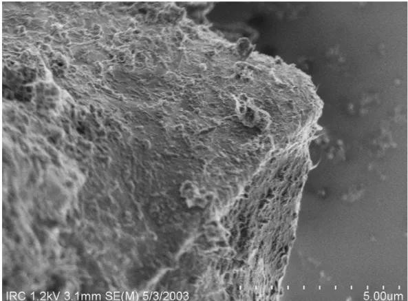
Both the paper and the ground powder were examined using a Hitachi S4800I cold field emission gun scanning electron electron microscope (SEM) at medium to high magnifications (25,000x to 200,000x). Figure 4 shows two images from the cement/CNT paper from near its outer surface. The scale bar in the images divides the scale into tenths of the indicated value, while the thickness of the lines that form the scale bar is a hundredth of the indicated value. In this region there is a porous structure and it is apparent that the sonication process has either not fully dispersed the carbon nanotubes, or that they have clustered together again during the evaporation process. The cement particles are attached both to each other and to multiple CNT. The central particle is coated with tube bundles of different diameters. It should be noted that individual CNT will be difficult or impossible to see in these images. While this microscope has the capability of resolving structures as small as 1.0 nm in size, it is more likely that the very fine structure, such as indicated by the arrow, are bundles of small numbers of CNT.
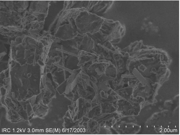
Figures 5 and 6 show grains of cement powder that have been well coated with CNT bundles after the paper has been broken apart by hand grinding. Figure 5 shows an image of a larger cement grain, while Figure 5 shows an image from agglomerations of smaller grains. In both cases large numbers of CNT can be seen on the grain surfaces. In figure 6 nanotubes can also be seen splitting off from larger bundles, along with loops and other structures. More nanotubes appear to be lying on the surface of the grain in Figure 5, while those on the smaller grains are more likely to be only anchored at one end.
Figures 3, 4 and 6 show different grain shapes, although all the cement grains in all three figures have a layered structure. Both the presence of layers in the unprocessed grains of Figure 3 and additional tests have shown that this layered structure is not due to the use of ethanol as a solvent. Instead, the sonication process used to distribute the carbon nanotubes appears to be breaking up some of the agglomerated cement grains. Shards from these grains are then caught at the top of the carbon nanotube paper as shown in Figure 4, while the coarser grains sink to the bottom of the paper. Additional experiments have shown that quality of the nanotube dispersion controls the size of the particles trapped at the top of the paper with smaller tube bundles trapping smaller cement particles. Grinding the nanotube paper frees up the larger particles but also allows clumps of smaller particles held together in part by nanotubes as shown in Figure 6 to form.
Figure 5 Carbon nanotubes distributed on a large cement grain
9 CONCLUSION
Carbon nanotubes are one of the most important materials under investigation for nanotechnology applications. Their unique properties, ranging from ultra high strength through unusual electronic behaviour and high thermal conductivity to an ability to store nanoparticles inside the tubes themselves has suggested potential applications in many different fields of scientific and engineering endeavour. As was the case with silicon transistor technology, these applications will grow in time as the capacity for industrial production and manipulation of CNT is created and as understanding of the physics of CNT continues to improve.
Construction industry applications of CNT range from composite materials through high strength structural components to heat transfer technology. Cement and concrete CNT composites have particularly strong potential, since CNT both act as a near ideal reinforcing material and have diameters similar in scale to the layers in calcium-silicate-hydrate. Current research has shown that it is possible to distribute CNT bundles across cement grains using an ethanol/sonication technique. Work is in progress to investigate the interaction between CNT and hydrated cement, including the mechanical performance of cement/CNT composites.
References
1. H. Dai, Topics in Applied Physics, 2001, 80, 29.
2. J.-C. Charlier and S. Iijima, Topics in Applied Physics, 2001, 80, 55. 3. J. S. Suh and J. S. Lee, Applied Physics Letters, 1999, 75, 2047.
4. R. R. Schlittler, J. W. Seo, J. K. Gimzewski, C. Durkan, M. S. M. Saifullah, M. E. Welland, Science, 2001 292, 1136.
5. S. G. Louie, Topics in Applied Physics, 2001, 80, 113.
6. P. G. Collins, K. Bradley, M. Ishigami, A. Zettl, Science, 2000, 287, 1801. 7. M. Ouyang, Science, 2001, 292, 702
8. P. J. de Pablo, C. Goméz-Navarro, M. T. Martinez, A. M. Benito, W. K. Maser, J. Colchero, J. Goméz-Herrero, and A. M. Basó, Applied Physics Letters, 2002 80, . 9. P. M. Ajayan and O. Z. Zhou, Topics in Applied Physics, 2001, 80, 391.
10. J.-P. Salvetat, J.-M. Bonard, N. H. Thomson, A. J. Kulik, L. Forró, W. Benoit, and L. Zuppiroli, Applied. Physics A, 1999, 69, 255.
11. M.-F. Yu, O. Lourie, M. J. Dyer, K. Moloni, T. F. Kelly, and R. S. Ruoff, Science, 2000, 287, 637.
12. D. A. Walters, L. M. Ericson, M. J. Casavant, J. Liu, D. T. Colbert, K. A. Smith, R. E. Smalley, Applied Physics Letters, 1999, 74, 3803.
13. O. Lourie, O., D. M. Cox and H.D. Wagner, Physical Review Letters, 1998, 81, 1638. 14. B. I. Yakobson and Ph. Avouris, Topics in Applied Physics, 2001, 80, 287.
15. S. Berber, Y.-K. Kwon, and D. Tomanek, Physical Review Letters, 2000, 84, 4613. 16. S.U.S. Choi, Z. G. Chang, W. Yu, F. E. Lockwood, and E. A. Grulke, Applied Physics
Letters, 2001, 79, 2252.
17. J. Hone, Topics in Applied Physics, 2001, 80, 273.
18. R. H. Baughman, A. A. Zakhidov and W. A. de Heer, Science, 2002, 297, 787. 19. A. Javey, Q. Wang, A. Ural, Y. Li, H. Dai, Nano Letters, 2002, 2, 929.
20. T. Tiamo, M. Roylance and J. Gassner, Proceedings of the 32nd International SAMPE Technical Conference, 2000, Boston, pp. 192.
22. T. Kuzumaki, O. Ujiie, H. Ichinose, K. Ito, Journal of Materials Research, 2002, 13, 2445.
23. R. Z. Ma J. Wu, B. Q. Wei, J. Liang, and D. H. Wu, Journal of Materials Science, 1998, 33, 5243.
24. G.-D. Zhan, J. D. Kuntz, J. Wan and A. K. Mukherjee, Nature Materials, 2003, 2, 38. 25. D. V. Smitherman, Space Elevators: An Advanced Earth-Space Infrastructure for the
New Millenium, NASA, 2000.
26. A. M. Neville, Properties of Concrete (4th Edition), 1995, 2.
27. C. Perry and J.E. Gillott, Cement and Concrete Research, 1977, 7, 553. 28. C. D. Johnston, Advances in Concrete Technology (2nd Edition), 1994, 603. 29. A. M. Neville, Properties of Concrete (4th Edition), 1995, 269.