HAL Id: hal-01894100
https://hal.archives-ouvertes.fr/hal-01894100
Submitted on 12 Oct 2018
HAL is a multi-disciplinary open access
archive for the deposit and dissemination of
sci-entific research documents, whether they are
pub-lished or not. The documents may come from
teaching and research institutions in France or
abroad, or from public or private research centers.
L’archive ouverte pluridisciplinaire HAL, est
destinée au dépôt et à la diffusion de documents
scientifiques de niveau recherche, publiés ou non,
émanant des établissements d’enseignement et de
recherche français ou étrangers, des laboratoires
publics ou privés.
Electrochemical and fractographic analysis of
Microbiologically Assisted Stress Corrosion Cracking of
carbon steel
Marko Stipaničev, Omar Rosas, Régine Basséguy, Florin Turcu
To cite this version:
Marko Stipaničev, Omar Rosas, Régine Basséguy, Florin Turcu. Electrochemical and fractographic
analysis of Microbiologically Assisted Stress Corrosion Cracking of carbon steel. Corrosion Science,
Elsevier, 2014, 80, pp.60-70. �10.1016/j.corsci.2013.11.009�. �hal-01894100�
OATAO is an open access repository that collects the work of Toulouse
researchers and makes it freely available over the web where possible
Any correspondence concerning this service should be sent
to the repository administrator:
tech-oatao@listes-diff.inp-toulouse.fr
This is an author’s version published in:
http://oatao.univ-toulouse.fr/20267
To cite this version:
Stipaničev, Marko
and Rosas, Omar
and Basséguy, Régine
and Turcu, Florin Electrochemical and fractographic analysis of
Microbiologically Assisted Stress Corrosion Cracking of carbon
steel. (2014) Corrosion Science, 80. 60-70. ISSN 0010-938X
Electrochemical and fractographie analysis of Microbiologically Assisted
Stress Corrosion Cracking of carbon steel
Marko Stipanicev
a,
c, Omar Rosas
b
,
c,
*
, Regine Basseguy
c, Florin Turcu
a •vet Norske Veritas,Johan Berentsens vei 109-111, 5163 Laksevcig, Bergen, Norwayb National Center for Education and Research in Corrosion and Materials Perfonnance, The University of Akron, 264 Wolfledges, Akron, OH 44325, USA c Laboratoire de Génie Chimique CNRS - Université de Toulouse (INP, UPS), 4 Allée Emile Manso, BP 84234, 31234 Toulouse Cedex 4, France
ARTICLE INFO ABSTRACT
This study was carried out ta evaluate the effect of microorganisms on the corrosion behavior of carbon steel when exposed ta mechanical axial stress. Open Circuit Potential (OCP) and Electrochemical Frequency Modulation (EFM) response were measured on the tensile specimens while applying a constant load in various environments inoculated with different sulfidogenic or iron reducing microorganisms. The fractographie analysis revealed a noticeable impact of the enriched environments on the topography of tensile specimens; however, after the tests were carried out, it was not possible ta detect any indications of a Stress Corrosion Cracking (SCC) failure mechanism for the tensile specimens. Keywords: Carbon steel Microbiological corrosion Pitting corrosion Stress corrosion 1. Introduction
The damage caused by corrosion to marine steel infrastructure, such as offshore oil production installations, is indisputable. Approximately 20% of the total corrosion cost in this industry is due to Microbially Influenced Corrosion (MIC) [1,2]. MIC is gener ally found and identified as the localized attack that is associated with the presence of surface-associated biofilms, e.g. microbial communities embedded in a bioinorganic matrix [3].
During oil production, besides the presence of bacteria, mechanical stresses are often seen as an additional component affecting the integrity of the material that leads to failures due to Stress Corrosion Cracking (SCC). SCC is a type of corrosion failure mechanism caused by a complex combination of factors including metallurgical, mechanical and environmental factors. The com plexity of
sec
has led over the years to numerous hypotheses, models, theories, and controversy on the mechanisms by whichsec
occurs. Among them, the dissolution of anodic sites on the metallic surface was sometimes claimed to be the origin for SCC[4]. When carbon steel is exposed to stresses and simultaneously to aggressive environment, the localized electrochemical dissolu tion of iron can result in mechanically initiated oxide film break down that leads to exposure of fresh anodic material to the
*
Corresponding author at: National Center for Education and Research in Corrosion and Materials Performance, The University of Akron, 264 Wolfledges, Akron, OH 44325, USA. Tel.: +1 3308613175.E-mail addresses: uberpomar@hotmail.com, orosascamacho@uakron.edu, omar. rosas@uakron.edu ( O. Rosas).
https: / /doi.org/10.1016/j.corsci.2013.11.009
corrosive medium [5]; in biotic conditions the localized electro chemical dissolution of metals (pitting) may be caused by the tubercle conditions that often lead to pitting corrosion; pitting is the predominant morphology of MIC [6]. The colonization of the metallic surfaces by bacteria and thus development of a biofilm may change the chemical conditions at the interface metal/envi ronment. Biofilm can create gradients of concentration of species across its thickness (100-400 µm) and the pH under the biofilm can decrease inducing severe corrosion conditions underneath the localized biomass.
A few more merging aspects regarding SCC and MIC acting on metal surfaces exist. Besides of their importance for
sec
mecha nism, microstructure irregularities, such as MnS inclusions, serve as initiation points for pitting in abiotic corrosion [7,8] and during MIC [9]. Avci et al. [9] suggested that, in presence of sulfidogenic bacteria, the initiation of an anodic reaction ( dissolution of the metallic iron (Fe) matrix) and the subsequent pitting of steel in the surrounding areas of MnS inclusions is due to the disorder and strain exerted on the Fe matrix by MnS regarded as a contam ination of the interface from metallurgical processes. Therefore, it is possible to assume that mechanical stress and bacterial activity may target the same locations on the material surface and syner gistically accelerate the deterioration process. Moreover, hydrogen is playing a different but important role in MIC and SCC deteriora tion processes jeopardizing bath, the material integrity and the mechanical properties [10]. This is often associated with absorp tion of hydrogen in metal structures, which is known as hydrogen embrittlement [ 11 ]. Thesec
and MIC environments support corrosion reactions due to capability to produce hydrogen invarious circumstances [10], for example, ferrous material being subject to tensile stress in an environment supporting the prolifer ation of hydrogen consuming Sulfate-Reducing Bacteria (SRB). Ten sile stresses cou pied with biological activity are an example of the synergie effect between
sec
and MIC that may be responsible for producing a local distribution of hydrogen [10].Despite the wide variety of bacteria found in aqueous environ ments, Sulfate-Reducing Bacteria (SRB) seem to have received extensive attention from the corrosion community due to their abundance in industrial facilities and in the oil and gas industry; however, the efforts for studying this type of environments have focus on either, the microbiological side or the electrochemical side; a combined study of electrochemical, topographical and mechanical characteristics of materials has not being carried out, especially considering recently developed electrochemical meth ods. Javaherdashti et al. [4,12] used pure and mixed cultures of SRB in Slow Strain Rate Testing (SSRT) on carbon steel, stainless steel and duplex steel finding that such materials are likely to fail in a shorter time compared to abiotic systems. However, these studies could be improved by estimating corrosion rates through electrochemical characterizations of systems under stress. On the microbiology side, focusing on one type of bacteria seems to limit the effect of bacteria other than SRB, such as iron reducing bacteria (!RB).
IRBs, such as Geobacter sulfurreducens ATCC 51573, have been widely studied for their use in microbial fuel-cells due to its electron exchange capabilities with solid substrates [13]. On the other hand, their role in corrosion process is still uncertain. Elec trochemical tests have shown that these bacteria can exert two dif ferent effects: (i) accelerating the cathodic reaction on the material hence, increasing the corrosion risk; and (ii) shifting the pitting po tential towards positive values, which may be interpreted as a reduction of localized corrosion risk. In the absence of an electron donor these bacteria promote the propagation of pitting whereas in the absence of electron acceptor is able to delay pit occurrence
[14]. Since bacteria can assist pitting and therefore lead to
sec
it is imperative to understand the role of bacterial activity on the Microbiologically Assisted Stress Corrosion Cracking (MASCC). For these reasons, studying the effect of different microorganisms on the corrosion of materials exposed to mechanical stress is impera tive and the tool to complement this study is the use of electro chemical techniques.Open Circuit Potential (OCP) has been used in corrosion studies for long time, especially for detecting potential ennoblement [15]
which, is the tendency of the electrode potential to become more positive. Ennoblement of ferrous metals in presence of biofilms most often leads to reaching the breakdown potential leading to crevice or pitting corrosion initiation. On the other hand, Electro chemical Frequency Modulation (EFM) [16,17] is a rather new technique used for corrosion monitoring in various environments and conditions [18,19]; however, there are just few references for EFM used for monitoring MIC [20] and none for carbon steel spec imens exposed to biotic environments while being under tensile stress. An advantage of using EFM resides in the small polarizing signais and its ability to provide promptly corrosion currents and causality factors ( considered to be a factor determining measure ment reliability), ail in a single experiment. In addition, prelimin ary knowledge of kinetic parameters, e.g. Tafel slopes, are not required. Since EFM possess a non-aggressive nature (minor system perturbation), it could be a promising method to monitor corrosion rates in environments supporting biological activity and therefore development of MIC. The current study comprises a combination of mechanical, topographical and electrochemical descriptions for S235JR carbon steel, when subjected to a constant Joad, in presence and absence of bacteria. Pure cultures of SRB, Des ulfovibrio alaskensis ALl and Desulfovibrio desulfuricans ATCC
27774, as well as IRB pure culture of G. sulfurreducens and con sortiums selected from water injection systems of the North Sea Oil and Gas (O&G) industry were used. A constant-Joad ring was used to apply a uniaxial stress on a tensile specimen while mea surements of OCP and EFM were simultaneously carried out. 2. Materials and methods
2.1. Test material
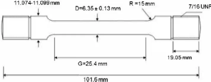
Carbon steel S235JR rod ( original diameter 2 cm) (Descoure and Cabaud, France) was used to fabricate rounded tensile specimens with the dimensions shown in Fig. 1. The composition and reported mechanical strength of the material are shown in Table 1. Speci mens were ground manually using SiC paper of increasingly fine grain, ending with 600-grit and then rinsed with sterile deionized water to eliminate remaining de bris from the grinding process. The specimens were exposed for 24 h to UV light (wave length 256 nm: XX-15, sterilization UV lamp, UVP, USA) at 25 °C before being introduced in the test vessels for sterilization.
2.2. Microbial cultures and growth media
Desufovibrio desulfuricans ATCC 27774 and D. alaskensis ALl
were provided by Bioin Departamento de Quimica Faculdade de Ciências e Tecnologia Universidade Nova de Lisboa. G. sulfurredu cens ATCC 51573 was purchased from DSMZ (Deutsche Sammlung
von Mikroorganismen und Zellkulturen). Consortiums used in experiments originated from pigging debris collected in water injection pipeline.
Saline modified-VMNI medium (2% or 3.5% NaCI) [21] served as a growth media for the pure cultures of SRB. The 2% and 3.5% NaCI modified VMNI media contained 0.37 mol 1.-1 and 0.62 mol 1.-1 of chloride ions. VMNI was composed of (g L -1 distilled water): NaCI,
20.0; NH4Cl, 1.0; CaClz x 2H2O, 0.04; Na2SO4, 4.5; MgSO4 x 7H2O, 0.06; FeSO4 x 7H2O, 0.004; sodium lactate, 6.0; KH2PO4, 0.5; so dium citrate, 0.3; casamino acids, 2.0; tryptone, 2.0; modified Wolfe's minerai elixir (0.1% v/v) and vitamin solution (0.2% v/v). The vitamin solution was composed of (g L -1 distilled water): ribo
flavin, 0.1; nicotinic acid, 0.25; thiamine, 0.3; pentatonic acid, 0.3; pyridoxine, 0.3; cyanocobalamin, 0.025; ascorbic acid, 1; biotin, 0.005. The composition of the modified Wolfe's elixir was (g 1.-1
distilled water): Nitrilotriacetic acid, 1,5; MgSO4 x 7H2O, 0.06; MnSO4 x H2O, 0.5; NaCI, 1; FeSO4 x 7H2O, 0.1; CoSO4 x 7H2O, 0.1; NiClz x 6H2O, 0.1; CuCl2 x 2H2O, 0.1; ZnSO4 x 7H2O, 0.1; CuSO4 x 5H2O, 0.01; AIK(SO4)2 x 12H2O, 0.01; H3BO3, 0.01; Na2_ MoO4 x 2H2O, 0.01; Na2SeO3 x 5H2O, 0.001.
G.sulfurreducens ATCC 51573 growth media was prepared fol lowing the DSMZ protocol for preparation of DSMZ 826 GEOBACT ER [22], and containing 0.05 mol 1.-1 of chloride ions. The DSMZ
826 GEOBACTER media was composed of (in 980 ml of distilled water): NH4Cl, 1.5 g; Na2HPO4, 0.6 g; KCI, 0.1 g; sodium acetate
11.074-11.099mm R=15mm
D=6.35�0.13mm 7116UNF
I.
j
19.05mmG=25.4mm
101.6mm
Fig. 1. Characteristics of the tensile specimen fabricated form S235JR carbon steel rod (with a 2 cm diameter).
Table 1
Chemical composition (wt%) and mechanical characteristic of S235JR carbon steel.
Alloy C Mn Cu s p
S235JR 0.17 1.40 0.55 0.03 0.03
0.82 g; trace element solution (medium 141 ), 10.0 mL; vitamin solution (medium 141 ), 10.0 mL; selenite-tungsten solution (medium 385), 1.0 ml; Resazurin, 0.5 mg; Narfumarate, 8.0 g; NaHCO3, 2.5 g. Pigging debris were cultivated in North Sea seawa
ter supplemented with 10 mM sodium acetate (Merck, Germany). The assessment of viable bacterial cells in enrichments was car ried out with a counting chamber (Helber Bacteria Cell Thoma from Hawksley, UK).
2.3. Test environments
The initial chemical composition of each test environment was identical to the growth media described in Section 2.2.
Inoculum-free filter-sterilized North Sea water or autoclaved modified-VMNI and DSMZ media were used for control tests. The pH of test environments was measured every 72 h (HI-9125N, por table pH meter, HannaNorden AB, Sweden). Each test vesse! con taining 333 mL of test media was inoculated with 37 mL of a particular culture. The control vessels were only filled with 370 mL of test media. Oxygen exclusion was achieved by bubbling argon gas (Vara Praxair, Norway) at high rate for 72 h before tests start. Moreover, low flow rate of argon was maintained during the tests.
For the sake of clarity, each test system (test vesse!+ bacteria) was assigned an identification code as indicated below:
CTRL1 system - specimen immersed in 2.0% NaCI modified
VMNI (autoclaved - no bacteria);
CTRL2 system - specimen immersed in DSMZ 826 GEOBACTER
media (autoclaved - no bacteria);
SW system - specimen immersed in North Sea water (filter ster
ilized - no bacteria);
DAL system - specimen immersed in 2.0% NaCI modified-VMNI
inoculated with D. alaskensis AL1 culture;
DDS system - specimen immersed in 3.5% NaCI modified-VMNI
inoculated with D. desul.furicans ATCC 27774 culture;
GBS system - specimen immersed in DSMZ 826 GEOBACTER
media inoculated with G. sul.furreducens ATCC 51573 culture;
PG system - specimen immersed in North Sea seawater inocu
lated with pigging debris isolate and being under tensile stress.
2.4. Constant load technique
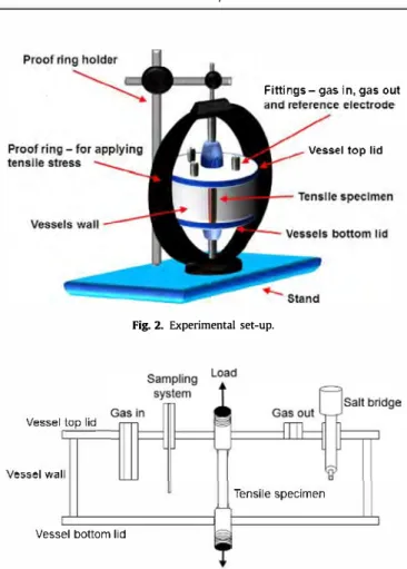
A tensile test-ring ( Cortest Proof Rings, Corrtest, USA) was used to apply the constant load to the steel specimen as shown in Fig. 2. Modified Cortest High Temperature Vessels (Cortest Proof Rings, Corrtest, USA) were used as test vessels. The wall and/or lids of these vessels were either made of Hastelloy C-276© or of Pyrex©. Transparent Pyrex© construction elements allowed for easier observation of the vessel's interior which permitted visual moni toring of the blackening resulting from the metabolic activity of sulfidogenic species (Fig. 3 ).
The design of the original test vessels was altered in way to per mit the installation of sait-bridges for accommodation of reference electrodes, and deaeration system.
Ali test elements (i.e. tensile specimens, vessels) were exposed for 24 h to UV light to eliminate any microorganism since they could have a collateral effect on the results.
N Certified yield (MPa) Tensile (MPa) Real yield (MPa)
0.01 235 360/510 406
Fittings- gas in, gas out
Vessel top lid
Fig. 2. Experimental set-up.
Vesse! top lid
Vessel wall
Tensile specimen
Vessel bottom lid
Fig. 3. Cross-section of test vesse!.
The applied constant load was the same for ail the experimental conditions; this load was chosen to not be greater than the yield strength to avoid any permanent deformation of the specimen. Ini tial applied Joad was 90% of material real material yield strength (Table 1 ). The Cortest Elapsed Time Monitors and Control Panels (Mode! 52000, Corrtest, USA) permit us independent regulation of each Cortest Proof Ring and provide possibility to perform multi ple tests.
2.5. Tensile tests
The yield strength or a yield point of a material is the parameter defined as the critical stress at which a material begins to deform plastically. Prior to the yield point the material will deform elasti cally and will return to its original shape when the applied stress is removed. Once the yield point is exceeded, the deformation will be permanent. Typically, steel will preserve its integrity during the expected lifetime given that load is below the yield point and steel is not exposed to an aggressive environment. One aim of the cur rent work was to assess the combined effect of biotic environment and mechanical load on the operational lifetime of the steel.
The assessment relied on a post-test analysis of tensile steel test specimens. Tensile tests were applied with aim to detect altera tions in specimens yield strength after exposure. Tensile testing was conducted with Zwick 2250 materials testing machine with central ball-lead screw and MIS 810 (MIS, USA) according to ISO
6892-1 :2009(E) entitled: Metallic materials-Tensile testing at ambient temperature.
2.6. Electrochemical techniques
A three electrode arrangement was used for performing the Electrochemical Frequency Modulation (EFM) and Open Circuit Po tential (OCP) measurement on carbon steel tensile specimens in the different test media. The tensile specimen was used as working electrode, while either the Hastelloy C-276© bottom !id or a vesse! wall was used as counter electrode. Electrochemical potentials were measured versus a commercial Saturated Calomel Electrode (SCE) (Gamry, USA) (Fig. 2) that was interconnected with test sys tems via sait bridges. Electrochemical tests were carried out using a multichannel potentiostat MultEchem™ (Gamry, USA) consisting of two Reference 600TM Potentiostat/Galvanostat/ZRA indepen dent units connected to PC interface and monitored by EFM140® software (Gamry, USA). Logging system comprised of SCXI (Na tional Instruments, USA) modules and LabVIEW software (National Instruments, USA) was used for the continuous recording of OCPs. Data were not recorded for the SW system.
OCP measurements were performed during the entire duration of the experiments. OCP of tensile specimens were sampled every 5 min. EFM measurements were performed every 72 h. A complex excitation signal consisting of two overlapping sine waves with frequencies of 0.02 Hz and 0.05 Hz and 10 mV amplitude vs. OCP was imposed to carbon steel specimen.
While using EFM, a potential perturbation signal composed of sum of two sine waves is a pp lied to the corroding specimen to ob tain the current response corresponding to different harmonie and intermodulation frequencies [22-25]. The fundamental principle of EFM is schematically presented in Fig. 4.
The stepwise analysis of the EFM output signal was performed by means of the Echem Analyst software (Gamry, USA). Firstly, activation controlled was assumed to be the dominating corrosion process and this assumption was taken in further calculations
[16,17]. Secondly, Altemating Current (AC) signais were trans ferred via a Fast Fourier Transformations (FFT) in the frequency do main. The resulting AC versus frequency curve is known as the "intermodulation spectrum". Thirdly, the intermodulation spec trum typically displays two distinguished peaks at 0.02 Hz and 0.05 Hz. Peaks observed in the region between 1 µA and 20 µA stands for the harmonies of the two excitation frequencies and they are used to calculate the corrosion current and the Tafel
lirsl inc wa-e
0 0 V V
Timedomain
second sine wave
=
Corroding surface Current = f (polential 1
Frequency domain
E
_____ ____,.,I Corroding surface
. i=f(E)
resul1am sine wave
currenl
Fig. 4. Principle of Electrochemical Frequency Modulation (EFM).
..
constants. Finally, the obtained corrosion current and Tafel con stants are used for calculation of corrosion rate.
Further, Echem Analyst ( Gamry, USA) software was used for cal culating values of causality factor 2 and causality factor 3.
2. 7. Gravimetric measurements
Weight Joss measurements were conducted on tensile speci mens. The tensile specimens were weighted prior and post to immersion (immersion period was 620 h). Tensile specimens were cleaned from corrosion products before post immersion weighting. For this tensile specimens were introduced in a 5% (v/w) hexamine (Merck, Germany) in concentrated HCI (VWR, USA) during 30 s, rinsed with deionized water and dried in the excess in a paper to wel. Furthermore, tensile specimens were rinsed in acetone (Sigma-Aldrich, Norway) and left to dry in desiccators for 24 h. The perfectly dried tensile specimens were weight in an analytical balance. Corrosion rate (CR) is given in mm y-1, and calculated according to Eq. (1):
CR(mm y-1) = (11.16 x X)/(t x A) (1)
where 11.16 is the factor accounting for the dimensional analysis and the density of the steel (7.85 g cm-3), X is the difference be tween "initial weight" and "weight after cleaning" in milligrams, t is the exposure time in hours, Ais the total area of the tensile spec imen in cm2•
2.8. Surface analysis of samples
Ali test specimens that were exposed to the test environments were analyzed with different surface analysis tools and methods. Photographs of ail exposed specimens were taken immediately after removal of specimens from test environments. Moreover, the presence of sulfide in formed black corrosion products was tested by initiating reaction between concentrated HCI (VWR, USA) and collected corrosion products [15].
Texture and morphology of each steel specimen after corrosion products removal were studied and documented with an upright DMR microscope (Leica, Germany) interfaced with ProgRes® CS camera OENOPTIK Optical Systems GmbH, Germany). Ali micro graphs were recorded at 1 x, 4x and 10x magnifications. Surface analysis was supported by micrographs obtained by means of table Scanning Electron Microscope (SEM) TM3000 (Hitachi, Japan) interfaced with Energy Dispersive X-ray (EDX) spectroscopy system Quantax 70 (Bruker, USA).
Oye penetrant testing was applied for detection of possible cracks. The acceptance criterion was in accordance with ISO 4987:2010, entitled: Steel castings - Liquid penetrant inspection. Oye penetrant test kit produced by Bycotest (Sweden) was used. 3. Results and discussion
In order to evaluate the bacterial activity in the biotic test ves sels, the number of bacteria at the end of the test period (620 h) was compared to the initial number of bacterial cells present in test vessels 1 h after the inoculation. According to Table 2, the cell density in each test vesse! was on average an order of magnitude higher at the end of the test. Considering that the contrai systems were sterile during 620 h of test, cell counts were not performed on CTRL1 system, CTRL2 system and SW system respectively.
Table 3 presents the pH evolution in ail test systems for the en tire duration of the test. It can be noticed three trends of pH, each one characteristic for a subgroup of test systems. The first sub group, consisting of bacteria containing DAL system and sterile CTRL1 systems, is featured with pH oscillating around 7.5. This
Table 2
Cell density (cell mL-1) monitoring for DAL, DDS, GBS and PG test systems.
Desulfovibrio alaskensis
AL1 {Code: DAL) Desulfovibrio desulfuricans ATTC 27774 {Code: DDS) ATCC 51573 {Code: GBS) Geobacter sulfu1Teducens Pigging isolate {Code: PG) te= 1 h cell mL-1 te= 620 h cell mL-1 Table 3 1.2 X 10⁷ 9.0 X 10⁷ 1.2 X 10⁷ 8.0 X 10⁷
pH values for CTRLl, CTRL2, SW, DAL, DDS, GBS and PG systems during 620 h of tests.
t (h) CTRLl DAL DDS SW CTRL2 GBS PG
Subgroup 1. Subgroup Il. Subgroup Ill.
0 7.5 7.5 7.5 7.8 7.5 7.5 7.5 50 7.3 7.4 6.8 7.6 7.8 7.9 7.9 200 7.5 7.9 7.0 7.9 8.5 8.2 8.3 350 7.4 7.4 7.0 7.2 8.4 8.4 8.3 500 7.5 7.5 6.6 7.3 8.5 8.4 8.1 620 7.5 7.7 6.7 7.3 8.5 8.3 I
stability observed in a case of CTRL1 system is attributed to the absence of bacterial communities which otherwise could alter the environmental conditions. The second subgroup, comprising bacteria containing DDS system and sterile SW system, shows a decreasing pH trend, from 7.5 to 6.7 and from 7.9 to 7.3, respec tively. The third group: encompassing CTRL2 system and GBS sys tem, demonstrates increase of pH toward alkaline values, for the GBS system this is caused by the presence of bicarbonate ions in the medium; in the case of PG system, a similar behavior was ob served for most of the test period.
Values of corrosion rates obtained by weight Joss for test sys tems are shown in Table 4 and photographs of ail exposed speci mens, taken immediately after removal of specimens from test environments are shown in Fig. 5.
Fig. 6A presents OCP of ail systems that used VMNI as a test media, e.g. CTRL1, DAL and DDS systems.
In the case of systems CTRL1 the OCP remained stable (-710 ± 15 mV /SCE) during the whole duration of the tests which is not surprising for a contrai system, e.g. anoxie saline media. Sim ilar OCP values for carbon steel in seawater were previously ob tained by other researches [26]. The stability of the recorded electrochemical signais ( system CTRL1) noticeable within the first 50 h of the test could be attributed to a steady protective layer formed at the metal- electrolyte interface. The steady layer might be explained by the low corrosion rate and consequently low iron concentration in bulk medium. In a neutral or slightly alkaline environment as in the case of CTRL1, the cathodic reduction of hydrogen ions would lead to hydrated hydroxide ions. Once the solubility product of iron hydroxide is reached in the vicinity of the metal surface it is imminent that a layer of ferrous hydroxide would loosely attach to the carbon steel thus conferring on it cer tain level of protection. Values of instantaneous corrosion rate ob tained by EFM were ranging between 0.003 and 0.044 mm y-1 (Fig. 6B) in the contrai systems. Furthermore, the figures obtained by weight loss measurements preformed on tensile specimens indicated 50% lower corrosion rates, of 0.02 mm y-1 (Table 4). This is not unexpected, knowing different natures of instantaneous cor rosion rate measurements (EFM) and absolute corrosion rate mea surements (weight loss). Corrosion tests, mostly weight loss
Table 4
3.0 X 10⁶
2.2 X 10⁷ 2.0 X 10
6
2.0 X 10⁷
Fig. 5. Photographs of tensile specimens (before cleaning) after 620 h of immersion in CTRL1, CTRL2, DAL, DDS, GBS and PG systems.
measurements, performed in similar environments with identical S235JR steel material ( coupons, 2 cm2) exhibited one order of mag nitude lower corrosion rates than the ones presented here; how ever, specimens ( coupons, 2 cm2) were not subjected to any mechanical stresses [27,28]. In addition, different dimensions of specimens used in two investigations could affect the result. There is a possibility that mechanical stress contributed additionally to the level of the metal loss by increasing the total corrosion of the specimen.
On the other hand, the OCP of DAL system largely varied on the first 48 h subsequent to test start. Moreover, OCP values of DAL system revealed a slow decline from -670 mV/SCE to -750 mV/ SCE). The large transients affecting the electrochemical potential trend of the DAL system tensile specimen at the beginning of the tests could be associated with the attack of the chloride ions on the metallic surface; the dynamic formation and dissolution of oxi des could have produced the rapid changes in the electrochemical potential. As soon as the charge transfer between the metal and the electrolyte stabilizes the transient phenomena are Jess prominent. In the case of the DAL system, the low sulfide concentration
Corrosion rates (CR) given in mm y-1 and obtained by weight Joss (mg) measurements of 5235JR carbon steel tensile specimens after 620 h exposures in CTRLl, CTRL2, DAL, DDS, GBS and PG systems. System Weight Joss (mg) CR(mm y-1 ) CTRLl 23.7 0.02 DAL 217.4 0.16 DDS 2472.2 1.85 CTRL2 154.3 0.12 GBS 11.5 0.01 sw 72.1 0.05 PG 264.8 0.20
(A)-o.58 -0.63
w
(.) -0.68 -0.73 --CTRL1 - - -DAL •••••• DOS.f.····
:'
· ...
. . ...,. ....
DDS:. . .
-0.78 ... ...,..., ... �.,... ... ..., ... .,...,...,..., (B) 0.25 0.2 >, 0.15 E .§. a:: 0.1 (.) 0.05 0 80 160 240 320 400 480 560 640 t (h) -.-CTRL1•
- ♦ -DAL DAL•
,, f
···•··· DOS'
\'
li
I \ I � I \ I I \ Is
'
"'
f
�
•
,
DDSË,
,'
0 80 160 240 320 400 480 560 640 t(h)Fig. 6. (A) Open Circuit Potential (Eocp(V/SCE)) for CTRLl, DAL and DDS systems during 620 h of tests; (B) Average corrosion rates (mm y-1) obtained with Electrochemical Frequency Modulation (EFM) for CTRLl, DAL and DDS systems during the 620 h of tests.
emerging form SRB's metabolic processes, could have promoted the formation of a stable and protective layer of pyrite or a differ ent stoichiometry of iron sulfide. A presence of iron sulfides was confirmed by quick test with concentrated HCI and visually was observed black layer, Fig. 5D. This is reflected in the steady OCP of DAL system. From a corrosion point of view, DAL system showed a higher instantaneous corrosion rate compared to CTRL1 system during the whole test. This rate increased the first 360 h, and re mained constant at 0.18 ± 0.05 mm y-1. On the other hand, corro sion rates estimated from weight Joss measurements were 0.16 mm y-1 (Table 4), a value similar to the ones obtained by
EFM technique.
For DDS system, OCP increased from approximately -710 mV/ SCE to -680 ± 15 mV/SCE (Fig. 6A). Unlike the other test systems, the DDS exhibited a porous and loosely bound black deposit ob served immediately after the tensile specimen extraction from the test environment (Fig. SE). The difference between this deposit and the one formed on the DAL system, originates in the particular chemical reaction pathway determined by the actual ratio between iron and sulfide ions [29]. Accidentai detachment of this layer might produce sudden large changes in the OCP. Corrosion rates reported by the EFM for DDS system were mostly Iow with the exception of very Iast measurement which indicated a higher cor rosion rate (0.23 mm y-1) (Fig. 6B). Nevertheless, the absolute
corrosion rate obtained by the weight Joss was significantly higher (1.85 mm y-1) (Table 4).
Although differences in biomineralization processes occurred on surfaces of the tensile specimens in DAL and DOS systems, the amount of aggressive chloride ions present in each system is pos sibly playing the major raie in degradation process. Pineau et al.
[30]observed a corrosion rate of 1.93 mm y-1 for carbon steel ex posed to seawater conditions while in an estuarine site, which im plies that the salinity is often much lower than the average salinity of seawater, observed corrosion rates were around 0.35 mm y-1. There is an obvious analogy between differences observed between DAL (CR= 0.16 mm y-1, 2% NaCI) and DOS (CR= 1.85 mm y-1, 3.5% NaCI) systems and differences between estuarine and seawater conditions.
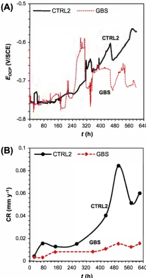
A comparison of OCP values measured in the system GBS and the corresponding contrai system CTRL2 (Fig. 7 A) shows that the OCP of CTRL2 drifts towards more positive values while in the case of GBS the drift is Jess pronounced. It is known that G. sulfurredu
cens promotes the formation of layer of iron phosphate in this
medium that is able to reduce corrosion on the steel surface (Fig. 5F) [4,19]; such layer is probably stabilizing the OCP of the tensile specimen in period between te = 0 h and te = 240 h. Fluctu ations observed after te = 240 h may be attributed to the close rela tionship established between the bacterial life cycles and general chemistry of test environment; hence, the global redox potential
(A) -o.5
w
-0.6 (.) LIJO -0.7 (B) 0.1 0.08-
>, 0.06 .§. a:: 0.04 (.) 0.02 --CTRL2 ---GBS...
...Ji
1:
i
ll .
1 ' 1: ' , 1 -...-- 1 1' '-., \, .. GBS� 0 80 160 240 320 400 480 560 640 t (h) � CTRL2 --♦--GBS GBS ,,♦ ....... ,• ♦---+-,k-•'
'"""
0 ._.,...,... ... ,..., ... .,...,...,...,..., ... -i 0 80 160 240 320 400 480 560 640 t (h)Fig. 7. (A) Open Circuit Potential (Eoep(V/SCE)) for CTRL2 and GBS systems during 620 h of tests; (B) Average corrosion rates (mm y-1) obtained with Electrochemical Frequency Modulation (EFM) for CTRL2 and GBS systems during the 620 h of tests.
of the electrolyte changing upon the variations in the bacterial growth and/or activity could be reflected in the OCP vs. time. How ever, it is important to notice that the OCP alone cannot completely describe the electrochemical behavior of an interface especially when bacteria are in close proximity. The absolute and instanta neous corrosion rates obtained at the end of test period are rela tively low (Table 4 and Fig. 7B), but are lower in presence of G. sulfurreducens: for GBS system, 0.015 mm y-1 obtained by EFM and 0.01 mm y-1 obtained by weight loss and for CTRL2 system,
0.06 mm y-1 obtained by EFM and 0.12 mm y-1 obtained by weight loss. It seems that the corrosion rates found here agreed with what is mentioned about a protection mechanism in presence of this bacteria as well as good corrleation between the very last instantaneous corrosion rates and the absolute corrosion rate. The observed protective effect was found previously [14,27] and it was attributed to the reduction of ferric ions by the iron reducing bacteria to ferrous ions, promoting the thermodynamic stability of iron phosphate compound, such as vivianite.
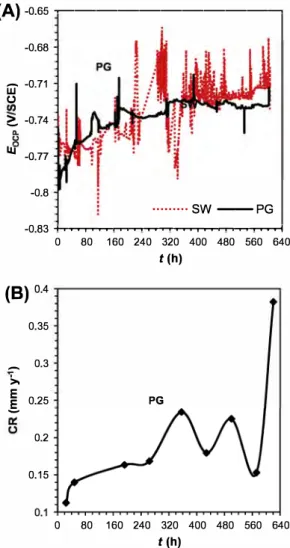
Fig. 8A compares the OCP values for PG system and its contrai (SW system). The OCP values remained stable for bath systems during the whole duration of the test. Unlike the SW system on which no deposits were found (Fig. SC), the tensile specimen of the PG system was covered by black precipitates of iron sulfide nature (Fig. SG). For the PG system, EFM corrosion rate (very last value of 0.38 mm y-1, Fig. 8B) and weight Joss corrosion rate
(A)
-o.65 �---� -0.68w
-0.71 (.) � -0.74 Ill -0.77 -0.8 ···SW--PG -0.83 +,-.,....,.. ... ,...,...,,..,...,...,..,....,.. ... ,...,,...,,..,...,. ... 0 80 160 240 320 400 480 560 640 t (h)(B)
o.4 0.35-
0.3 >, E 0.25 PG.s
0.2 0.15 0 80 160 240 320 400 480 560 640 t (h)Fig. 8. (A) Open Circuit Potential (Eocp(V/SCE)) for SW and PG systems during 620 h of tests; (B) Average corrosion rates (mm y-1) obtained with Electrochemical Frequency Modulation (EFM) for the PG system during the 620 h of tests.
(0.20 mm y-1, Table 4) were considerably higher than for the con trai system (weight loss corrosion rate 0.05 mm y-1
). This higher
corrosion rate is attributed to the effect of the SRBs found in the "pigging" debris used to cultivate this inoculum [27]. In this case, black deposits were observed (that released the smell characteris tic for H2S in reaction with diluted hydrochloric acid) indicating
the presence of iron sulfides. Even though they are different micro bial population, it is possible to observe similar behavior and cor rosion rates between the two sulfidogenic systems, PG and DAL.
According to the available literature, EFM may show contradic tory results when applied to corrosion rate determination as it was shown in particular examples presented above. Obviously, there is an apparent discrepancy between the corrosion rates obtained by weight Joss and EFM technique, however, deviations varies from system to system. Sorne discrepancies are enormous, for example in the case of the DDS system, while in other cases most of the deviations are acceptable. The reasoning why these differences are considered as acceptable is the very nature of the corrosion techniques that were used; EFM provides instantaneous corrosion rate white weight loss provide absolute corrosion rate. From other point of view, reliability ofEFM corrosion rates can be questionable depending on the situation and may be the cause of the observed discrepancies. When EFM is applied for measurement of high cor rosion rates, the technique provides valid and reasonable values, for example for mild steel in a 0.05 M H2SO4 solution where it can reach value of 2.1 mm y-1 [19]; on the other hand, when ap plied for measuring low corrosion rates, it provides non-reliable values [19]. In order to validate EFM measurements, causality fac tors were used. Causality Factor 2 (CF2) and Causality Factor 3 (CF3) are in general used to validate the data obtained by EFM in case of uniform corrosion. Usually, if the CF2 values are close to 2 and the CF3 values are close to 3, it is considered that measure ments are conducted correctly and obtained corrosion rates are va lid [24]. These assumptions are valid only when uniform corrosion mechanism is present and care must be taken when localized at tack is dominant; in this latter case, a deeper analysis regarding corrosion rate and the values for CF must be carried out. For exam ple, CF2 and CF3 can be applied as a valuable tool for detection of localized corrosion as it is shown by Rauf and Bogaerts [24] who proposed a causality factor evaluation mode! for localized corro sion. The values for CF2 and CF3 were analyzed following the main observations and conclusions extracted from the literature but having on mind the possible impact of tensile stress on the ac quired data.
In Fig. 9A, it is possible to observe that most of the CF2 values are in range between 0.5 and 2; there are few exceptions above the upper limit of this range and they are deviating for the general corrosion expected value of 2. Fig. 9B reveals that most of the CF3 values are in the range between 0.5 and 2; although only some exceptions fall outside the mentioned upper and lower limits, most of the values are still deviating from the expected value of 3.
The PG system showed EFM corrosion rate values (with excep tion of very last one) not too far from the ones obtained by weight loss, which is in agreement with CF2 values; however, CF3 deviates from the expected value of 3. Similar good correlation between corrosion rates obtained by EFM in seawater environment as in a case of PG system was presented by Han and Song [18], however, causality factors values were not reported in that particular case. The values for CF2 and CF3 for the DDS system on the time interval te= 140 h to te= 180 h, were above 2 and below 3 respectively. These CF values were previously used as an indication of localized and crevice corrosion [24], and it the case of DDS system an ele vated localized surface attack by sulfidogenic bacteria was ob served; it is believe that this amount of localized attack influences the calculation of corrosion rate and it is the cause for the discrepancies found between the EFM method and weight loss
(A)
4.o 3.5 3.0(B)
4.o 3.5 3.0 2.5 u.. 2.0 (.)<>
6
0
0 80 160 240 320 400 480 560 640 0 CTRL1 X PG<>
)K t {h) ♦ CTRL2 6 DAL ♦ DOS X GBS 0 80 160 240 320 400 480 560 640 o CTRL1 X PG t (h) ♦ CTRL2 6 DAL X GBS 0 DOSFig. 9. Causality factors values obtained by Electrochemical Frequency Modulation (EFM) for CTRLl, CTRL2, DAL, DDS, GBS and PG systems during the 620 h of tests; {A) Causality factor 2 (CF2); (B) Causality factor 3 (CF3).
method for corrosion rate. The DAL system, that had sulfidogenic nature, was showing high CF3 but low CF2 values which possibly could be regarded as an indication of localized pitting events occurring on the specimen surface [24]; however this is not always applicable as it was shown for this particular case.
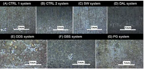
To validate the electrochemical findings and to provide an in sight into the surface degradation mechanism, visual and micro scopical examinations of the exposed specimens were conducted. Black corrosion products were observed along the body of the ten sile specimens immersed in the DAL, DDS and PG media as it was expected due the sulfidogenic nature of the systems (Fig. 5).
The morphology of the black deposits built on these specimens varied significantly among the three test systems. Tensile speci mens from DAL system were covered by a thin, homogenous and strongly adhering black layer, which is consistent with the low cor rosion rates and stable OCP. On the other hand, the specimens im mersed in PG and DDS environments showed a high volume and loosely bond black products. As previously mentioned, the DDS system experienced a massive deterioration noticed as high EFM and weight loss corrosion rates (Fig. 10).
The chemically cleaned tensile specimens previously exposed in DDS system were characterized by severe localized corrosion as it
(A)
CTRL
1 system, 620 h exposure
(B) DOS system, 620 h exposure
--�
...
Fig. 10. Macrographs (1 x) of tensile specimens after 620 h of immersion in DDS and CTRLl (belonging contrai system) systems.
is shown in Fig. 11E, where large pits are observed (diameter of a 1-2 mm and depth between 10 and 30 µm). The severity of the localized corrosion damage in terms of affected area was much lower for the PG system compared to the DDS specimens (Fig. 11G, respectively). The observed pit morphology on speci mens immersed in DDS, BS and PG systems is not the typical fea tured in standard SSC tests.
The tensile specimens from DAL system (Fig. 11D) are charac terized, after a chemical cleaning, by a smooth surface and the ab sence of localized damage which could be attributed to a stable and thin black protective surface layer of iron sulfides. A similar condition was previously observed by other workers in low sulfide environments [28,31 ].
Evidence of pitting was found in tensile specimen in GBS test; however, these pits were smaller in size compared to DDS system and homogeneously distributed ail along the surface of the metal lic specimen (Fig. 11F). Observations are in correlation with previ ously observed Geobacter nature. Geobacter was earlier tested due
to the ability of this microorganism to exchange electrons with so lid substrates, it is believed that during the constant mechanical load, cathodic and anodic micro-zones are created on the surface of the specimen which attracts the bacteria and facilitates their settlement.
In order to achieve a definitive result on the extent of the pit ting, ail specimens, regardless the presence of visible pits, were subjected to a dye-penetrant test and to careful microscopie
Fig. 11. Macrographs (4x) of cleaned tensile specimens after 620 h of immersion in CTRLl, CTRL2, DAL, DDS, GBS and PG systems.
Fig. 12. Macrographs (1 x) of tensile specimens that was submitted to tensile test after 620 h of immersion in the AL test system under Joad of 90% of its actual yield strength; (A) Elongated sample (necking) and (B) ductile brake.
Table 5
Results of post-exposure tensile tests performed on steel specimens immersed in CTRLl, CTRL2, SW, DAL, DDS, GBS and PG systems during 620 h of tests. Presented parameters: A= fracture percentage elongation, Rpo.2 and Rp1 = proof strength (plastic extension), R.L = lower yield strength, ReH = upper yield strength, Rm = tensile strength, Z = percentage
reduction of area, E = modulus of elasticity.
System A(%) Rpo.2 (MPa) Rp1 (MPa) ReL (MPa) ReH (MPa) Rm (MPa) ReH/Rm (%) Z(%) E (GPa)
Dummy0• 1 35.7 338 333 327 391 455 89.40 69 224.0 CTRLl 32.3 322 335 322 373 461 80.91 68 198.3 SW 38.5 330 320 320 382 462 82.68 63 196.2 DDS 47.4 321 319 309 352 447 78.75 70 204.0 PG 37.2 332 332 324 416 460 90.44 70 230.0 CTRL2 29.4 406 405 I I 515 I 65 211.8 DAL 20.2 515 528 I I 588 I 62 209.1 GBS 34.2 324 342 I I 468 I 68 225.5
A= fracture percentage elongation, Rpo.2 and Rp1 = proof strength (plastic extension), ReL = lower yield strength, ReH = upper yield strength, Rm = tensile strength, Z = per
centage reduction of area, E = modulus of elasticity, • average of three, 1 Dummy - is the specimen not exposed in any media and machined according to standard requirement for tensile testing.
examination. Nevertheless, none of the tensile specimens pro duced any evidence of crack initiation.
Common post-exposure mechanical tests, such as hardness and tensile, performed on ail tensile specimens exhibited a pronounced plastic deformation (necking) before suffering ductile fractures. An as example, the tensile specimen exposed to DAL system is shown in Fig. 12.
Tensile tests revealed differences and similarities in properties of the exposed specimens (Table 5). A dummy specimen (not ex posed in any media and machined according to standard require ment for tensile testing) was subject to tensile test in order to provide reference values. This sample exhibited a yield curve char acterized with upper and lower yield point, and displayed tensile
strength (Rm) of capped carbon steel [32]. Tensile specimens form CTRLl, SW, DOS and PG systems exhibit identical shape of yield curve as the dummy specimen, and they demonstrated tensile strength similar to dummy specimen.
A contrasting behavior is discovered in the case of the tensile specimens who were immersed in CTRL2, DAL, and GBS systems. Those systems have shown a yield curve with offset yield point and a slightly higher tensile strength (from 468 MPa to 588 MPa) compared to dummy specimen. At the same time, for these tensile specimens, the percentage of elongating (A) was reduced com pared to dummy specimen. This gives an indication of an increased embrittlement of the tensile specimens, most probably due to hydrogen (present as a product of the cathodic reaction) diffusion
� MS. 1 . /n .me us1on � y -Ferrite 1 100 um
Fig. 13. SEM micrograph (1000x) of ferrite/perlite microstructure typical for ail tested S235JR carbon steel tensile specimens.
in metal structure. Embrittlement was expected in the case of hydrogen sulfide environments, like in the DAL system, hence, a lower mechanical resistance was also expected in the samples ex posed in this test system.
The irregularities in the tensile tests results could be caused by variations in post-exposure tensile specimens dimensions (hetero geneous distribution of deformations due to weight Joss). Tensile test are based on a standardized geometry and surface finish of samples which means that irregularities can lead to deviation in results.
Even though tensile test are performed on unstandardized spec imens it is possible to detect certain common patterns in their mechanical behavior. For example, percentage reduction of area (Z) of ail specimens was in range of 60-70%, as well as modulus of elasticity (E) in range of 195-230 MPa, indicating similar behav ior of ail tested specimens.
Hardness for ail tensile specimens, including dummy specimen, was in the same range, around value of 180 according to Rockwell scale (it decreases in close proximity of break point) indicating same mechanical properties of tested specimens, either they were exposed to environment inoculated with bacteria or not, or even not being exposed to any aqueous environment (dummy speci men). Further investigation revealed homogenous ferrite/perlite microstructure characterized by small grains and relatively short grain boundaries (20-40 µm). In addition, long and narrow MnS inclusions were present in carbon steel structure (Fig. 13). In this particular investigation it was not possible to detect pit initiation on week points in carbon steel microstructure (MnS inclusion)
[9]that could lead to crack initiation. This result shows that there was not change in microstructure properties of tested specimens.
4. Conclusion
The current study comprised a combination of mechanical, topographical and electrochemical descriptions for S235JR carbon steel subject to a constant axial Joad in presence and absence of different types of bacteria from the water injection systems of the North Sea Oil and Gas (O&G) industry.
The presence of microorganisms produced accelerated corro sion rates in some test systems but the pits formed as a result of this corrosion do not present a threat that would lead to initiation of cracks. There was no evidence of
sec
initiators, such as inter granular or transgranular corrosion failure mechanisms.According to results, it is clear that the presence of bacteria may change the metallic surfaces by inducing the formation of pits. In
the case of the DOS system, the pits are produced under a layer of corrosion products like iron sulfides; in the case of GBS, the pres ence of bacteria produces a non-uniform layering of iron phos phate, it is believed that the pits are produced by a non-uniform bacterial attachment when the stress produces cathodic and ano dic micro-zones. It was not possible to correlate the formation of pits with the presence of MnS inclusions or possible synergetic ef fect of mechanical stress and microbial activity on weak spots in carbon steel microstructure. To investigate this feature it is most likely required to study this phenomenon at earlier stages, when pit initiation is expected, and at higher tensile stress.
The type of surface degradation e.g. pit morphology for tensile specimens exposed in sulfidogenic systems (shallow and wide pits), such as in the case of tensile specimen retrieved from DOS system, do not correlate with pit morphology observed in standard SCC tests conducted in inorganic hydrogen sulfide environments. This is indicating that surface degradation is more likely to be the result of bacteria activity within biofilms formed on tensile specimens surfaces, than to be a product of global test environ ment. In addition, is it likely that formation of porous and unstable iron sulfide corrosion products lead to localized corrosion attacks
[29]. Iron sulfide corrosion product alone, or coupled with formed organic biofilm structures, could lead to the establishment of suit able conditions for formation of galvanic couples what could ex plain higher weight Joss for studied DOS system. In the case of DAL system, a layer of stable protective iron sulfides was formed
[29], protecting the specimen from corrosion but not from hydro gen penetration.
The environment was affected by the presence of micro-organ isms and their metabolic activity; this may lead to larger altera tions in the material corrosion resistance rather than in the mechanical behavior of the exposed tensile specimens. Signs of embrittlement were observed from the mechanical tests, but it is not possible differentiate the origin of this behavior, or to attribute it solely to microbial activity or to effect of mechanical stress or maybe to joined action of these two parameters.
The discussed observations on causality factors and obtained corrosion rates suggest that EFM measurements conducted on mechanically stressed specimens in microbial environments may give correct corrosion rates even though causality factors indicate failed measurements. Nonetheless, deeper investigating on this particular issue is required.
Acknowledgments
Funding was received from the European Community's Seventh Framework Programme (FP7 /2007-2013) under Grant Agreement Number 238579. The authors wish to express their gratitude to wards Inge Buanes Roth from Det Norske Veritas in Bergen and to Dr. Leonardo Dall'Agnol and Prof. Jose Moura from Faculdade de Ciências e Tecnologia Universidade Nova de Lisboa for their sup port in the production of the present work.
References
[1] E. Heitz, H.C. Flemming, W. Sand, in: W. Sand (Ed.), Microbially Influenced Corrosion of Materials, first ed., Springer Verlag GmbH & Co KG, Berlin, 1996. [2] LB. Beech, J. Sunner, Biocorrosion: towards understanding interactions
between biofilms and metals, Curr. Opini. Biotechnol. 15 (2004) 181-186. [3] M. Madigan, J.M. Martinko, P.V. Dunlap, D.P. Clark, in: L Berriman, G. Carlson
(Eds.), Broek Biology of Microorganisms, twelth ed., Pearson-Benjamin Cummings, San Francisco, 2012.
[ 4] R. Javaherdashti, R.K. Singh Raman, C. Pan ter, E.V. Pereloma, Microbiologically Assisted Stress Corrosion Cracking of carbon steel in mixed and pure cultures of sulfate reducing bacteria, I. Biodeteriorat. Biodegradat. 58 (2006) 27-35. [5] H.H. Uhlig, R.W. Revie, Corrosion and corrosion contrai, in: H.H. Uhlig, R.W.
Revie (Eds.), An Introduction to Corrosion Science Engineering, fourth ed., John Wiley and Sons, New York, 2008.
[6] R. Javaherdashti, Microbiologically influenced corrosion, in: R. Javaherdashti (Ed.), An Engineering Insight, first ed., Springer, London, 2008.
[7] G. Wranglen, Active sulfides and the pitting corrosion of carbon steels, International Conference on Localized Corrosion, Williamsburg, VA, USA, 1971, pp. 462-476.
[8] G. Wranglen, Pitting and sulphide inclusions in steel, Corros. Sei. 4 (1974) 331-349.
[9] R. Avei, B.H. Davis, M.L. Wolfenden, LB. Beech, K. Lucas, D. Paul, Mechanism of MnS-mediated pit initiation and propagation in carbon steel in an anaerobic sulfidogenic media, Corros. Sei. 76 (2013) 267-274.
[toi M.V. Biezma, The role of hydrogen in microbiologically influenced corrosion and Stress Corrosion Cracking, Int. j. Hydrogen Energ. 26 (2001) 515-520. [11] V. Novokshchenov, Brittle fractures of prestressed bridge steel exposed to
chloride-bearing environments caused by corrosion-generated hydrogen, Corrosion 6 {50) (1994) 477-485.
[12] R. Javaherdashti, R.K. Singh Raman, C. Panter, E.V. Pereloma, Role of microbiological environment in chloride Stress Corrosion Cracking of steels, Mater. Sei. Tech. 21 (9) (2005) 1094-1098.
[ 13] D. Bond, D.R. Lovley, Electricity production by Geobacter sulfu1Teducens attached to electrodes, Appl. Environ. Microbiol. 69 (2003) 1548-1555. [14] M. Mehanna, R. Basseguy, M.-L. Delia, A. Berge!, Geobacter sulfu1Teducens
can protect 304 L stainless steel against pitting in conditions of low electron acceptor concentrations, Electrochem. Commun. 12 (2010) 724-728.
[15] B.J. Little,J.S. Lee, Microbiologically Influenced Corrosion, first ed.,John Wiley and Sons Inc., Hoboken, New Jersey, USA, 2007.
[16] R.W. Bosch, W.F. Bogaerts, Instantaneous corrosion rate measurement with small-amplitude potential intermodulation techniques, Corrosion 52 (1996) 204-212.
[17] R.W. Bosch,J. Hubrecht, W.F. Bogaerts, B.C. Syrett, Electrochemical Frequency Modulation: a new electrochemical technique for online corrosion monitoring, Corrosion 57 (2001) 60-70.
[ 18] L. Han, S. Song, A measurement system based on Electrochemical Frequency Modulation technique for monitoring the early corrosion of mild steel in seawater, Corros. Sei. 50 {2008) 1551-1557.
[19] E. Ku�. F. Mansfeld, An evaluation of the Electrochemical Frequency Modulation (EFM) technique, Corros. Sei. 48 (2006) 965-979.
[20] P. I Beese, H. Venzlaff, J. Srinivasan, J. Garrelfs, M. Stratmann, K.J.J. Mayrhofera, Monitoring of anaerobic Microbially Influenced Corrosion via Electrochemical Frequency Modulation, Electrochim. Acta 105 (2013) 239-247.
[21] V.V. Zinkevich, LB. Beech, Screening of Sulfate-Redueing Bacteria in colonoscopy samples from healthy and colitic human gut mucosa, FEMS Microbiol. Ecology 34 (2000) 147-155.
[22] Deutsche Sammlung von Mokrooganismen und Zellkulturen DSMZ GmbH, Microorganisms, 826, Geobacter medium, 2007.
[23] G.S. Frankel, Electrochemical techniques in corrosion: status, limitations, and needs,j. ASTM In. 5 (2) (2008) 1921-1929.
[24] A. Rauf, W.F. Bogaerts, Employing Electrochemical Frequency Modulation for pitting corrosion, Corros. Sei. 52 (2010) 2773-2785.
[25] A. Rauf, E. Mahedi, Comparison between electrochemical noise and Electrochemical Frequency Modulation measurements during pitting corrosion,J. New Mater. Electrochem. Syst. 15 (2012) 107-112.
[26] F.M. AIAbbas, R. Bhola, j.R. Spear, D.L. Oison, B. Mishra, Electrochemical characterization of microbiologically influenced corrosion on Iinepipe steel exposed to facultative anaerobic Desulfovibrio sp, Int. J. Electrochem. Sei. 8 (2013) 859-871.
[27] C. Cote, PhD thesis, University of Toulouse, France, 2013.
[28] L. Dall'Angol, PhD thesis, Faculdade de Ciêneias e Tecnologia Universidade Nova de Lisboa, Lisbon, 2013.
[29] H.A. Videla, L.K. Herrera, R.G. Edyvean, An updated overview of SRB influenced corrosion and protection of carbon steel, Corrosion 2005, NACE International, Houston, TX, 2005, Paper no. 05488.
[30] S. Pineau, R. Sabot, L. Quillet, M. Jeannin, C. Caplat, I. Dupont-Morral, P. Refait, Formation of the Fe(II-III) hydroxysulphate green rust during marine corrosion of steel assoeiated to molecular detection of dissimilatory sulphite-reductase, Corros. Sei. 50 (2008) 1099-1111.
[31] M. Stipanicev, PhD thesis, University of Toulouse, France, 2013.
[32] By the ASM committee on Carbon and Alloy Steels, Properties and Selection: Irons and Steels, in: B.P. Bardes (Ed.), Metals Handbook Ninth Edition, vol. 1, ASM, Ohio, 1978, pp. 253-259.