HAL Id: hal-02777391
https://hal.archives-ouvertes.fr/hal-02777391
Submitted on 4 Jun 2020
HAL is a multi-disciplinary open access
archive for the deposit and dissemination of
sci-entific research documents, whether they are
pub-lished or not. The documents may come from
teaching and research institutions in France or
abroad, or from public or private research centers.
L’archive ouverte pluridisciplinaire HAL, est
destinée au dépôt et à la diffusion de documents
scientifiques de niveau recherche, publiés ou non,
émanant des établissements d’enseignement et de
recherche français ou étrangers, des laboratoires
publics ou privés.
Validation of image restoration methods on 3D-printed
ultrasound phantoms
Krisztián Füzesi, Adrian Basarab, György Cserey, Denis Kouamé, Miklós
Gyöngy
To cite this version:
Krisztián Füzesi, Adrian Basarab, György Cserey, Denis Kouamé, Miklós Gyöngy. Validation of
image restoration methods on 3D-printed ultrasound phantoms. 2017 IEEE International Ultrasonics
Symposium, Sep 2017, Washington, United States. pp.1-4, �10.1109/ULTSYM.2017.8092120�.
�hal-02777391�
OATAO is an open access repository that collects the work of Toulouse
researchers and makes it freely available over the web where possible
Any correspondence concerning this service should be sent
to the repository administrator:
tech-oatao@listes-diff.inp-toulouse.fr
This is an author’s version published in:
https://oatao.univ-toulouse.fr/22080
To cite this version:
Füzesi, Krisztián and Basarab, Adrian and Cserey, György and
Kouamé, Denis and Gyöngy, Miklós Validation of image
restoration methods on 3D-printed ultrasound phantoms. (2017) In:
2017 IEEE International Ultrasonics Symposium, 6 September 2017
- 9 September 2017 (Washington, United States).
Open Archive Toulouse Archive Ouverte
Official URL :
Validation of Image Restoration Methods
on 3D-Printed Ultrasound Phantoms
Kriszián Füzesi
1, Adrian Basarab
2, György Cserey
1, Denis Kouamé
2, Miklós Gyöngy
11Faculty of Information Tecnology and Bionics, Pázmány Péter Catholic University, Budapest, Hungary 2IRIT, CNRS, University of Toulouse, Université Paul Sabatier, Toulouse, France
Abstract—The resolution of ultrasound images is limited by the bandwidth of the imaging system and the features of the propagating medium. Using certain assumptions, image restoration can recover out-of-bandwidth data and improve resolution. Several resolution improvement methods have been reported in the literature. However, due to the lack of ground truth, their evaluation on experimental data remains an open issue. Indeed, to evaluate the performance of such methods, knowledge of the scattering function is necessary. Usually this is achieved with numerical simulations, since in traditional phantoms the exact distribution of scatterers is unknown. In the current work, based on a 3D-printed phantom, the feasibility of the evaluation of deconvolution is investigated. The deconvolution method used lp-norm-regularization terms with p=0.5 and p=2.
Knowledge of the scattering function allows comparison of the deconvolved images with the ground truth. Thus, using the scattering function and the originally acquired B-mode image, performance of image restoration methods could be evaluated quantitatively through comparison of root mean square error and full width half maximum values. Preliminary results demonstrate the benefits of knowing the scattering function during experimental testing of image restoration methods. In summary, the current work shows the potential of an experimental method for evaluating the extent to which an image restoration method provides a faithful rendering of the underlying scattering structure.
Keywords-image restoration, deconvolution, phantom manufacture, 3D printing
I. INTRODUCTION
A. Image restoration problem
The resolution of ultrasound images depends on the central frequency and bandwidth of the imaging system, as well as the physical properties of the propagating medium. Using a convolutional model of image formation, the radiofrequency (RF) ultrasound image can be approximated by the shift-invariant convolution of the original scattering function (also known as the tissue reflectivity function [1]) with the imaging system response or point spread function ℎ [2]:
= ℎ ∗ + , (1)
where ∗ is the 2D convolution operator and is additive noise, often assumed to be zero mean Gaussian white noise. Thus, the resolution of the image is limited by the bandwidth of the point spread function ℎ, and image restoration or resolution enhancement consists of restoring out of bandwidth data. This is
a well-known ill-posed problem. To solve this problem, additional assumptions about are thus required by adding a regularization term into the cost function to be minimized and to find x. Assuming x is distributed as generalized Gaussian (random) variable with parameter p, the minimization problem becomes:
arg min ‖ − ℎ ∗ ‖ + λ‖ ‖ , (2) where λ expresses the relative contribution of the prior term and determines the nature of the sparsity assumption. With = 2, the problem becomes the classical least-squares Tikhonov regularization, while values closer to 0 impose a stronger sparsity assumption.
Many approaches exist for solving (2); for more information, the reader is directed to [3, 4]. One of the most used methods is the alternating direction method of multipliers (ADMM) [5].
B. Validation of image restoration
Given the plethora of image restoration algorithms available, the question arises as to their applicability for real ultrasound images. Assuming the shift-invariant convolution model is accurate, simulations provide a method of checking solutions against a ground truth. However, any limitations of the model may degrade real-life results. For instance, shift-variance of ℎ [6] may need to be accounted for by splitting the image into blocks, and even without shift-invariance, errors in estimating ℎ may lead to restoration errors. In addition, non-linear propagation and/or scattering will also invalidate the model, the latter often causing image degradation that is partially responsible for image clutter [7].
Previous work has shown that a collection of polystyrene microspheres aligned on a planar surface may be used to investigate the validity of the shift-invariant convolution model [8]. This in turn may be used to assess the performance of image restoration methods. However, the method in [8] is limited as it does not allow precise positioning of the microspheres. Alternate possibilities are laser printing and transfer of patterns onto a phantom surface [9] or printing of filaments using low-cost 3D-printing technology [10]. However, neither methods allow the positioning of spherical scatterers in a 3D volume.
Recent work by Jacquet and colleagues [11] has shown that using photopolymer jetting (PPJ) technology, phantoms containing high precision scatterer maps can be manufactured. The printer settings need to be modified to limit the polymerization of the support material, thus making it a suitable
propagation medium. The Objet series of Stratasys (Eden Prairie, MN, USA) printers are able to create objects within a planar resolution limit of 42 μm and a layer thickness of 16-28 μm, depending on the type of the printer. The technology therefore offers a high degree of flexibility when creating customized 3D structures. In the current work, this capability is explored for creating a desired scattering function and assessing the accuracy of a recently published fast image restoration algorithm based on ADMM numerical optimization scheme [12, 13].
II. METHODS
A. Phantom design and manufacture
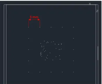
The phantom was designed to contain: an outer frame of scatterers to check for the consistency of the printed scatterers and the point spread function ℎ (the latter only expected to change in the axial direction); and an inner frame with a high concentration of scatterers so as to generate speckle (Fig. 1). The diameter of the spheres was set to 100 μm, which was found to be the smallest size that could be printed with reliable size.
Figure 1. Phantom design. In the outer frame, spheres were placed at 5 mm distances to each other and at least 10 mm from the walls. In the
middle 10×10 mm region, 40 spheres were placed at random X-Z positions.
To generate the file used to print the phantom, the scatterer locations were first defined in MATLAB (The MathWorks, Natick, MA, USA). A MATLAB script was then used to generate an AutoCAD script file (‘.src’), which was imported in AutoCAD 2017 (Autodesk, San Rafael, CA, USA). The AutoCAD design was then exported as an ‘.stl’ file recognized by the printer software (Objet Studio, Stratasys, Eden Prairie, MN, USA).
To print phantoms, an Objet24 printer (Stratasys, Eden Prairie, MN, USA) from Stratasys was used. Similarly to Jacquet et al. [7], the minimally polymerized support material (FC 705) acted as propagation medium, while the scatterers and the walls were made of VeroWhitePlus (VWP). The VWP wall was placed on 5 sides around the support material to minimize creep
of the support material, thereby increasing the accuracy of scatterer placement. All scatterers were placed at least 10 mm from the walls to minimize reflections from them.
To ensure the support material did not polymerize, the printer settings needed to be modified (see Table 1). These settings are available under File/Build Properties. In the settings of “Main Grid”, the grid width should be as small as possible, while for the grid step a large value must be chosen, both for the X-Y printing direction.
Setting name Setting value
Main Grid
Grid Type Step Grid
Grid Width X 0.09 Y 0.09 Z 2 Grid Step X 50 Y 50 Z 0 Fine Grid
Outline with fine grid No
Grid Thickness X&Y Z 0.6 0 Grid X&Y sizes Width 0.09
Step 0.17
Body outline X&Y Z 0.35 0
Table 1.The parameters in the table were modified in “File/Build Properties” menu, “Lite Grid” tab.
B. Imaging
The ultrasound images were obtained using uniform delay (“plane-wave”) emission from a 47.0 mm, 3-10 MHz linear array (LA522E, Esaote, Genoa, Italy) connected to an ULA-OP Research US system (MSD Lab, University of Florence, Florence, Italy).
Previous experiments on FC 705 have shown that water absorption causes cracking and degradation of the material. Therefore, instead of a water-based gel, the unpolymerized support material was used as the coupling medium between the transducer and the phantom.
The center frequency of the array was set to 4MHz. The propagation speed was set to that of the photopolymer gel (1660 m/s). The ultrasound wavelength was therefore 415 μm, yielding
ka=0.76, that is, a fair (if imperfect) approximation to a point
scatterer.
Further signal processing was carried out in MATLAB (The MathWorks, Natick, MA, USA). Digital time gain compensation (TGC) was applied to compensate for acoustic attenuation, and hard thresholding was used to eliminate noise in regions without scatterers.
C. Assessment of image restoration accuracy
The image restoration algorithm follows a recently developed fast, iterative, ADMM-based, lp-norm-regularized
deconvolution method [12]. Although any 0 < ≤ 2 could be chosen, to make the investigation tractable, = 0.5 and 2 were compared, as they provided a good contrast between a highly sparse and a non-sparse solution. The algorithm-specific
parameters [12] were manually set by cross-validation to their best values.
To estimate the point spread function h, the response to one of the scatterers on the outer frame was recorded. A 2-D parabolic window was applied to h in order to avoid edge effects during the deconvolution procedure.
Two measures of image restoration accuracy were used. The lateral and axial full width half maxima (FWHM) of an isolated scatterer on the outer frame of the phantom was calculated. The inner frame was used to calculate the normalized root mean square error (RMSE) of the true scattering function estimates.
III. RESULTS AND DISCUSSION A. Phantom quality and reproducibility
The reproducibility of phantom printing can refer to reproducibility between or within phantoms. While accurate scatterer positioning could be achieved with a judicious choice of printing parameters, it was found that even using the same printer settings, some printed phantoms showed contamination of the propagation medium with scattering material. The reason behind this merits further investigation. Although scatterer diameters as low as 50 μm could be printed, setting it to 100 μm (the setting presented in the current work) substantially reduced variations in scatterer diameter. As regards variations of scatterer printing within phantoms, Fig. 2 shows the B-mode image of a successfully printed typical phantom. It can be observed that the lateral variation of the scatterer responses around the outer frame is relatively small compared to the axial variation. This suggests that the scatterer diameters are fairly reproducible, with the relatively high amplitude of the response at 20 mm hypothesized to be due to elevational focusing of the transducer. As judged by the location of the outer ring of scatterers, the scatterer placement is also accurate.
B. Assessment of image restoration accuracy
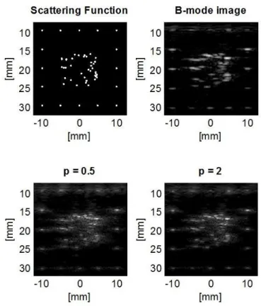
Figure 2 shows a comparison of the scattering function, the resulting B-mode image, and deconvolved images for = 0.5 and 2. It can be observed that the spatial response to the outer frame of scatterers is made more spatially compact by deconvolution. Furthermore, many scatterers in the center of the images are close enough that they cannot be distinguished on the B-mode image, while deconvolution allows the separation of many of these scatterers. However, the difference between the deconvolved images for = 0.5 and 2 is more difficult to ascertain visually and calls for the use of metrics.
Table 2 lists the resulting FWHM and RMSE values. For the settings used, = 0.5 offers a higher spatial resolution gain than = 2, and also provides a higher estimation accuracy of the scattering function in terms of RMSE. However, it can also be observed qualitatively that = 0.5 has a tendency to amplify noise. Indeed, for other settings, = 0.5 still yields better values of FWHM than = 0.5 but with similar RMSE values, arguably due to increased noise.
B-mode
image Restored image (p = 0.5) image (p = 2) Restored
FWHMx [mm] 1.42 0.78 0.98
FWHMz [mm] 0.37 0.26 0.27
RMSE 2.34 1.87 1.93
Table 2. Axial and transverse FWHM values of a single scatterer from the outer frame of the phantom shows an improvement in resolution using p = 0.5
and p = 2 norms. RMSE values obtained using the inner random scatterer pattern.
A meaningful definition of the signal to noise ratio (SNR) still needs to be established that can quantify the effect of noise amplification. In the current work, the SNR had been calculated using a region of the image containing both signal and noise and a region containing just noise (due to orthogonality, the variances of signal and noise levels can be assumed to be additive). However, the measure gave misleading results since the noise levels in the region with and without signal were not necessarily the same.
Figure 2. Scattering function of our phantom, the obtained B-mode image and two resulting images of the algorithms using p = 0.5 and 2 norm. Clusters of
IV. SUMMARY
The current work has shown how photopolymer jetting (PPJ) 3D printing technology can, with a careful choice of settings, be used to print phantoms with a known scattering function. This allows the testing and comparison of image restoration methods, using metrics such as the root mean square error (RMSE) to measure the difference of the solution from the true scattering function. Although the current method is limited to the use of a single scatterer material, some PPJ printers allows the use of several materials, allowing even greater flexibility in setting the scattering function. Moreover, modification of the support material could also lower the current speed of sound of 1660 m/s to speeds closer to tissue (generally assumed to be around 1540 m/s), and could also set attenuation to a prescribed level. In addition to modification of the scattering and propagation materials, further work needs to establish realistic scattering functions for tissue that can be used as realistic test beds for image enhancement techniques.
ACKNOWLEDGMENT
The authors would like to thank Jean-René Jacquet for his help in setting the printing parameters as well as Varinex Zrt., providing access to change the necessary printer settings.
Krisztián Füzesi, Miklós Gyöngy and György Cserey were supported by Pázmány Péter Catholic University KAP R&D and equipment grants (2014-2018). Miklós Gyöngy was supported by the János Bolyai scholarship of the Hungarian Academy of Sciences and Grant PD 121105 of the Hungarian National Research, Development and Innovation Office (NKFIH).
Adrian Basarab and Denis Kouamé were partially supported by the CIMI Labex, Toulouse, France, under grant ANR-11-LABX-0040-CIMI within the program ANR-11-IDEX-0002-02 and by ProSmart Solutions, 6-12 Rue Andras Beck 92360 Meudon, France.
REFERENCES
[1] O. V. Michailovich and A. Tannenbaum. "Despeckling of medical ultrasound images," IEEE Trans Ultrason Ferroelectr Freq Control, vol. 53, no. 1, pp. 64-78, 2006.
[2] J. C. Bamber and R. J. Dickinson, “Ultrasonic B-scanning: A computer simulation,” Phys. Med. Biol., vol. 25, no. 3, pp. 463–479, 1980. [3] M. V. Afonso, J. M. Bioucas-Dias, M. A. T. Figueiredo. "An augmented
Lagrangian approach to the constrained optimization formulation of imaging inverse problems," IEEE Transactions on Image Processing, vol. 20, no. 3, pp. 681-695, 2011.
[4] M. Elad, Sparse and Redundant Representations From Theory to
Applications in Signal and Image Processing. New York: Springer, 2010.
[5] M. Renaud, A. Basarab, and D. Kouamé. "Alternating direction method of multipliers framework for super-resolution in ultrasound imaging,"
Biomedical Imaging (ISBI), 2012 9th IEEE International Symposium on. IEEE, 2012.
[6] J. Ng, R. Prager, N. Kingsbury, G. Treece, A. Gee. “Modeling ultrasound imaging as a linear, shift-variant system,” IEEE Trans Ultrason
Ferroelectr Freq Control, vol. 53, no. 3, pp. 549-563, 2006.
[7] B. Byram, K. Dei, J. Tierney, D. Dumont. “A model and regularization scheme for ultrasonic beamforming clutter reduction,” IEEE Trans
Ultrason Ferroelectr Freq Control, vol. 62, no. 11, pp. 1913-1927, 2015.
[8] M. Gyöngy and Á. Makra. "Experimental validation of a convolution-based ultrasound image formation model using a planar arrangement of micrometer-scale scatterers," IEEE Trans Ultrason Ferroelectr Freq
Control, vol. 62, no. 6, pp. 1211-1219, 2015.
[9] K. Füzesi, “Development of a PVC-based ultrasound phantom”, Technical Report, Faculty of Information Technology and Bionics, Pázmény Péter Catholic University, 2015.
[10] K. Füzesi and M. Gyöngy. "Comparison of Two Inexpensive Rapid Prototyping Methods for Manufacturing Filament Target Ultrasound Phantoms," Ult Med & Biol, vol. 43, no. 3, pp. 712-720, 2017.
[11] J. R. Jacquet, F. Levassort, F. Ossant, J. M. Grégoire. "3D printed phantom for high frequency ultrasound imaging." Ultrasonics Symposium
(IUS), 2015 IEEE International. IEEE, 2015.
[12] N. Zhao, Q. Wei, A. Basarab, N. Dobigeon, D. Kouamé, and J. Tourneret. "Fast Single Image Super-Resolution Using a New Analytical Solution for ℓ2-ℓ2 Problems." IEEE Transactions on Image Processing, vol. 25, no. 8, pp. 3683-3697, 2016.
[13] N. Zhao, Q. Wei, A. Basarab, D. Kouamé, and J. Tourneret. “Super-resolution of medical ultrasound images using a fast algorithm” IEEE
International Symposium on Biomedical Imaging From Nano to Macro, Prague, 13/04/16-16/04/16, IEEE, pp. 473-476, 2016.