Publisher’s version / Version de l'éditeur:
Translation (National Research Council of Canada), 1949-11-01
READ THESE TERMS AND CONDITIONS CAREFULLY BEFORE USING THIS WEBSITE.
https://nrc-publications.canada.ca/eng/copyright
Vous avez des questions? Nous pouvons vous aider. Pour communiquer directement avec un auteur, consultez la
première page de la revue dans laquelle son article a été publié afin de trouver ses coordonnées. Si vous n’arrivez pas à les repérer, communiquez avec nous à PublicationsArchive-ArchivesPublications@nrc-cnrc.gc.ca.
Questions? Contact the NRC Publications Archive team at
PublicationsArchive-ArchivesPublications@nrc-cnrc.gc.ca. If you wish to email the authors directly, please see the first page of the publication for their contact information.
NRC Publications Archive
Archives des publications du CNRC
For the publisher’s version, please access the DOI link below./ Pour consulter la version de l’éditeur, utilisez le lien DOI ci-dessous.
https://doi.org/10.4224/20386606
Access and use of this website and the material on it are subject to the Terms and Conditions set forth at
Embedded Pipes: Static Investigation of Embedded Conduits with Consideration Given to Their Elasticity
Voellmy, A.
https://publications-cnrc.canada.ca/fra/droits
L’accès à ce site Web et l’utilisation de son contenu sont assujettis aux conditions présentées dans le site LISEZ CES CONDITIONS ATTENTIVEMENT AVANT D’UTILISER CE SITE WEB.
NRC Publications Record / Notice d'Archives des publications de CNRC:
https://nrc-publications.canada.ca/eng/view/object/?id=80aab6e1-fb99-4b26-9192-3d4eb1ba609c https://publications-cnrc.canada.ca/fra/voir/objet/?id=80aab6e1-fb99-4b26-9192-3d4eb1ba609c
Title:
Author: Reference: Translator:
NATIONAL RESEARCH COUNCIL OF CANADA Technical Translation TT-131
Embedded pipes.
(Eingebettete Rohre). Adolf Voe1lmy.
Proc. Inst. Building Statics, Zurich, 1937. H.L. K9.sten.
FOREWORD
The tollowing pages contain a translation
ot
VoellmyVs paper on Eingebettete Rohre (Embedded Pipes).
This paper was published in 1937 by Gebso Leeman & Coo,
Zurich and Leipzig, as a proceeding of the Institute
ot
Building Statics, Federal Institute of Technology, Zurich. The paper consists of four main sections as
tollows.
(a) Earth pressures on embedded structures
with-out consideration of deformation conditions.
(b) The stressing of embedded structures dependent
on their deformations.
(c) Research. .
(d) The practical computation of embedded pipes.
The whole field of stresses due to earth pressure on buried structures is quite complicated and few engineers have the basic mathematical knowledge, or the time, to go
into detailed theoretical studies of the SUbject. However,
the practical application of Voellmy's analysis is not dif-ficult and, due to the outstanding importance of the topic, it seemed to the writer that a translation of the fourth chapter would be well worth while in order to make available to other engineers what seems to him an excellent method of design of underground conduits.
In spite of a very bUsy academic session,
Mr
o Kastenhas very kindly devoted much of his leisure time to writing
out the translationo The figures have been reproduced by
photography and the German words substituted by their English equivalent so
It is hoped that this monograph will be found to be immediately useful in the design of such structures as properly come within its scopeo
PREFACE
The National Research Council, through its
Division of Building r・ウ・セイ」ィL is pleased to have
been able to arrange for the publication of this translation of an important paper in the field of
civil engineeringo The significance of the paper
is indicated in the Foreword by Professor 10 Fo
Morrison, of the University of Alberta, who brought the translation to the attention of the
under-signed.
The publication of this translation repre-sents one way in which the Division of Building Research hopes to work with the engineering and architectural departments of Canadian universities in the co-operative development of bUilding research
in Canadao
November 8th, 1949
R0ᄋfセ Legget, Director.
VOELLMY:
comENTS OF CHAPTER IV
CHAPTER IV: THE PRACTICAL ANALYSIS OF EMBEDDED PIPES
Page No.
10 STRESSING OF PIPES WITH LINEAR REACTION • • • • • • • • • (2)
Ao Earth Pressure, Disregarding Deformation Conditions. • (2 )
(a) Pipes in Extensive Fills • • • • • • • • • • • • • (2)
(b) Pipes in Trenches 0 • • • • • • • • • • • • • • • (5)
Bo Earth Pressure on Rigid Pipes • • • • • • • • • • • • (6 )
(a) Pipes in Extensive Fills • • • • • • • • • • • • • (6 )
(b) Pipes in Trenches 0 0 0 0 • • 0 • 0 0 • • • • • • (8)
Co External and Internal Water Pressure; Dead Weight • • (9)
Do Surface Loads • • 0 • • • • • • • • • • • • • • • • • (9)
2 0 EFFECT OF REACTION CONDITIONS 0 • • • • • • • • • • • • (10)
3. EFFECT ON STRESSES OF THE CURVATURE OF THE PIPE WALL
• •
(12)4. SIMPLIFIED COMPUTATION OF RIGID PIPES • • • • • • • •
•
(14)50 STRESSING OF ELASTIC PIPES 0 • • • • • • • • • • • • •
•
(15)60 EXAMPLES OF PIPE ANALYSIS " • 0 • • 0 • • • • • • • •
•
(21)Ao Pipe in Extensive Fills 0 0 0 e • • 0 • • • • • •
•
(21)Bo Pipe in Trench 0 0 0 0 0 0 e • 0 0
•
0 • 0 • • • ••
(24)70 DESIGN SPECIFICATIONS 0
" 0
" e 0 0 0 0 0 0 0 0 • • • 0 (26)
Ao Strengths and Moduli of Elasticity of Pipe Materials (26 )
1.
CHAPTER IV
THE PRACTICAL ANALYSIS OF EMBEDDED PIPES
Summar:
The previous chapters of this work have shown the varied earth loads possible on embedded structures, depend-ing on the shape and deformation cond1 tions of the structure. Great numbers of individual investigations concerning the most important problems in soil mechanics would be necessary
to gain the complete picture
ot
the stressingot
embeddedworksD whereatter the necessarily simplified assumptions tor
their practical analysis could properly be adoptedo The
princi ples
ot
static analysis developed in the previouschapters are applicable to embedded structures of several
different formso Since in many cases a circular cross-section
allows a "closed" mathematical analysis» this investigation
has dealt mainly with pipeso Furthermore, the investigation
is narrowed down by considering only pipes embedded at a constant depth along their axeso
In this chapter the computations for the pressures on embedded pipes are brought together in simplitied form9
For sake of completenessD the computation for stresses in
pipes due to surface 10adsD dead weight, and inner and outer
water pressure have also been includedo
In conclusion a few figures on the strengths and
moduli
ot
elasticityot
various pipe materials have been10 STRESSES WITH THE PIPE ON LINEAR SUPPORT
The computation of inner stresses of the pipe which follows immediately is based on the assumption that the pipe
rests on a linear support. Later, in section 2 of this chapter,
the added effect of a distributed reaction pressure is
investi-gatedo As the usual methods of analysing stresses in pipes
unaer given external loads offers nothing fundamentally new, a repetition herein of the rather complicated developments and
formulae was avoidedD and only the internal forces at the crown,
side» and sole of the pipe are giveno Should the complete
dis-tribution of the internal stresses be desired for some special
pipe analysisp then this may be solved in a simple manner in
that a knowledge of the values of M and N at the pipe crown as
given in the previous chapter makes the ウゥ、・セィ。ャヲ of the pipe
statically determinateo The variation of internal forces from
crown to sole may be computed with no further information
necessarY9 since those values of the internal forces at the pipe side and sole as given in the next sections serve as controls
for the computationo Under all cases of symmetrical loading
the shearing force at the crown disappearsl Q
=
00 It maybe pointed out here that the moment on the pipe side is the maximum of the positive moments only in case the bedding of
the pipe is very wide «(1'0 -;;;;:; 90°), as will be shown in the
developments that follow o Normally the maximum value of the
positive moment lies below the pipe side, and is up to 10% greater than the side-moment for normal earth loadso
Ao EARTH PRESSURE WITHOUT REGARD TO DEFORMATION CONDITIONS
(a) Pipes in Extensive Fillso
The active earth pressure on a structure is but little
affected by the deformation of the samep if the earth cover is
shallow» i oe 0 9 when the depth of cover does not exceed the
breadth of the structureo In this case, the earth pressure can
be found using already well known earth pressure bheor-Les ,
Those computation methods which are based on Coulombvs theory
results in good agreement with test results o In contrast,
Rankinevs somewhat more inaccurate application of the theory of an unbounded earth body yields a clearer picture of the
pressure c ondf tionsg and was tor thi's reason applied in this
analysiso An extension of Rankinevs theory was however
neces-sarY9 in order to' take care of all possible inclindations of the walls of embedded structures sufficiently accurately
(Section I, 1 = Equation 8)0 As the side pressures on the
embedded pipes reduce the stressing of the pipe somewhat, the usual computation is based on the lower limit of the side
pressure0 The distribution of the active earth pressure ma'y
then be calculated from equations (11) and (12) of Chapter I.
p=
30
Figure 0
For the upper halt of the pipes
a:
'Y cosri) (1 + sinp. cos 2 IZ)*= 1 + sinp(to + r •
(1) 7" =
1
,.. (t + r • cos d.) (sinp. sin2tt)c:. + sinp 0
For the lower halt
ot
the pipesc
I :(fo(
1 - taneJ
u tan C(
(2)
-r:
セ 0where 'Y
=
Unit weightot
till material oAngle of internal friction of fill materialg
. approxo equal to its angle of reposeo
to I : Depth of fill over pipe centerlineo
r I : Radius of pipe (outer).
DC
=
Aqgle to locate the element of the pipeキ。ャャセ
The pressure distribution thus found serves a s a basis for the analysis with consideration given to the rigidity
of the pipe, which becomes important when depth of cover is great o
The internal stresses in the pipe due to the above given equations of pressure distribution (1 and 2) were com-puted based on the previously given method of pipe analysis
(Section II - 4 - 8 - d) and the resulting moments and normal stresses at the crown, sides, and sole of the pipe are given in Figo 1 for various values of the angle of internal
fric-tion,
p
0 The coefficients for the internal stresses {Moment,M and Normal Stressg N)g assuming a linear reaction, are plotted
positive outwards in a radial direction from the pipe
centre-line in the Figureo With these values known, the computation
of the complete variation of stress throughout the pipe wall, if desired, is a simple matter, since the system is statically determinate; in this way, it is also easy to check the
correct-ness of the given figures o
=
porosityセ]
lf
w=
specific weight of water =·1 t/m3'7
=
0; -
"Yrセ
セN
=
unit weight of fill material in dry conditionoThe angle of internal friction pmay be set equal to
the natural angle of repose with sufficient accuracyo Its
value is not affected much by a varying moisture content of
the fill material; however, the apparent cohesion (Section I - 1)
increases with decreasing motsture contento For the
compu-tation of earth pressure on a pipe under fill, the effect of
the cohesion may, as a ruleg be allowed for in approximate
fashion by increasing the'angle of frictiono Clayey materials
back-filled in the dry state become crumbly due to the apparent cohesion, and the angle of friction for gravelly material is
reached0 If clayey material is put in very wet, then following
drying-out, a very large reduction in side pressure takes ーセ。」・L
again due to apparent cohesion and shrinkageo In this case,
for the sake of safety, a value of the angle of internal
friction
p
セ 900 should be uaed ,The unit weight セ of loose fill material at first
decreases with increasing moisture content, and reaches a
minimum at a definite water content {around 3% for coarse sand)o This minimum is about 15% less than the unit weight in a dry
conditiono On further increase in moisture content, the unit
weight begins to increase and finally surpasses the weight for
the dry conditiono If all the voids are filled with waterg
then the unit weight is:
'1",,=
(1 ....'1)
セG..
'1(,
where50
If no test values セッイ angle of internal friction
and unit we ght are available, then for rough computations the following values may be usedl
For gravel and sands at natural moisture content
to wet, clayey materialsI
Angle frictionI
P
=
35° toP
=
20°Unit weight:
Y
= 107 t/m3 to Y = 201 t/m3(b) Pipes in Trenches
As shown previously (Section I - 6), for the case of pipes in trenches, most commonly-used backfill materials may be regarded as incompressible; in this event, the pressure
on the crown of a pipe embedded in a trench with vertical or slightly outward sloping sides is found as followss
q = qoo
P
where qo= Y.t = hydrostatic earth pressure
セ = 1 ... e-x x
e = 20 7 1 8 = base of natural logs
(4)
t = depth of cover over crown
_ t I 0 1 ... sin
p
=セ
y
(5)x - - 0 tan
p
1 + sin p
b
b = half-width of trench at the level of the crown of the pipe
p
= angle of internal friction of backfill セnatural angle of reposeo
I
P
= angle of friction developed at wall of trenchoNumerical values of the function
t
may be taken from F1g o 2for different values of the quantity x =
!
i
0 In this Figurealso, values
ヲッイセ
are given for variousセ。ャオ・ウ
of P , computedon the assumption that p =
P ,
which is close enough forpractical purposes o
For the computation of the inner stresses in the pipe
the side pressure may be neglected in most caseso This 1s
be-cause the backfill will likely not be properly tamped into the narrow space between pipe and trench wall; also, as shown in
Section I CD 5, the lateral pressura is greatly reduced in such
60 The theoretical investigation of the same section (I - 5) also showed that it is sufticiently accurate when considering such pipes in trenches. to take the loading as evenly distributed over the horizontal projection of the pipe o
The internal stresses may then be found using the
equations and coefficients of Figo 19 if セィ・ tollowing
sub-stitutions are made thereins
Depth of cover to
=
t 0 セ , wheret
is taken fromFlgo 2 using values
ot
P • PlOt the backfill material and .trench dimensions b and to (Reduction of vertical pressure)o
Coefficients
m, n
=
a
in the equations of Figo 1tor M and N (Vertical pressure taken as uniform over the horizontal projection)o
Find values of coefficients m and n when
P
=
90°trom the curves
ot
Figo 1 and substitute these into theequations for M and N (no lateral pressure)o
When these substitutions are made one arrives at
the practical formulae for computation as given in Figure 20
Bo EARTH PRESSURE ON RIGID PIPES
The loading of rigid pipes forms the basis for the later investigation of the stressing or elastic pipeso
Furthermore, pipes or relatively small diameter made
ot
suchmaterials as plain or reintorced concrete, stone blocks, or vitrified clay may be considered as completely r1gido
(a) Pipes in Extensive Fills o
The settlement of the fill at the sides of a'stift pipe results in a relief of pressure in the fill itselt, and
an added load on the pipe o Above the pipe there exists a
certain zone of earth which is compressed under a pressure greater than the hydrostatic earth pressure at, that deptho
The height of this "zone of disturbancen ·is given by the
fol-lowing conditions, as preViously listed in Section II セ 2 -
A,
equations
(15), (18)g
and(19)1
(6) :it. u uo= -
u' II V . u 2 2 V Rセー|u+
(v) (21" - 1) - 1 4utJ.!
+ h J! - 1 ..t.t\ U . /" 0 V; the other symbols are as given in Figo 30*
•
In this Figureot
the square,tCCj
2bo
=-;
セ。ッ This gives the lengthot
the s1deand u
=
0For any given value ot セ D there are two roots
tor
セ
trom equation (6)0 otエィ・ウ・セ
the smaller is to be used,u
as may readily be seen trom the boundary conditions!! = co 0
u
By assundng セ and
;u
one can compute thecorrespond-ing values ot セLu as has tor example been done in Fig o 24 (p07l)
tor the case セ
=
0, io eo Uo=
00Also, it tor a given value ot !! the corresponding
value ot
セ
is known, then, as shown inウ・セエゥッョ
II - 2 - A,equation Y14), the average specitic vertical loading on the rigid pipe is:
(rr -
セIM
セj
(7)This pressure is somewhat high when considered in
the light ot the discussion at the end ot Section II - 2 - Ao
It, trom equation (6), セ \セ then one must
sub-u u
stitute セ
=
!! into equation (7), since under these conditionsu u
the upper 'limiting value is reachedo
In order to tind the added pressure due to the
(8) The result iss
D q
=
Y u,"74
ャセ Hセ
-
セI
-.
セ
+セ}
In order to simplity practical computations, the values ot セ
have been computed trom equation (6) as a tunction ot the
depth=ot=cover condition セ tor various embedment depths in
u
stift soils:;U = 0, 0025 , 0059 00 75 and 10000 These have been
substituted in equation (8) with the result that the added
ーセ・ウウオイ・セョ rigid pipes in extensive fills may be taken directly·
trom Figo 30
The internal stresses in the pipe due to the added
pressure セ q are tound from the tormulae ot Figure 2, it
in-stead of the crown pressure アセ the added pressure セセア is
sub-stitutedg The added stresses thus found must then be
(12)
80
(b) Pipes in Trenches
For rigid pipes in trenches there also exists a
ウオー・イg」ッューイ・ウセ・、 earth zone. the extent of which" and the resulting added pressure" may be found from the theory of
Section II G 2 セ Bo For practical purposes. the following
closely approximate ヲッセオャ。・ suffice -- (compare Figo 25g
po7l).
The uniformly 、ゥウエイゥ「オセ・、 specift6 vertical
pressure is. .
f
b 2 ... b 2]
q
=
-y' 2 0 cot ..p.
+
セN
セ
(9)r a ra
where bo:ll セT ora (10)
and tV
=
to - bo - (b-bo) 」ッセッp (11). The numerical value· of セ may be taken from Figo 2
. . t' ...
T.
"I.T,
for values
ot
the functionx:;
b
01" •
where y is alsogiven in Flgo 2 as a function of the· angle of internal
friction
p
=
P'o
If formula
(11)
for tV becomes negativeg then thefollowing equation must be used in place of HYIセ
セ to cD .bo
r:
q
=?'
2r セ「ッ+
(to ... bo)tanP
(upper limiting value of earth pressure when depth of cover i·s small)
...
The pressure
q
of equation (9) becomes greater withincreasing width of trench until it finally reachesv at great
depths of backfill and a very wide trench width 2b*g the value
セ for extensive f lIs as given by equation (7)0 This latter
value of
q
then remains constant for all wider trenches( b > b*)0
For very rough computations of pipes in relatively narrow trenches g· the following approximate formula will serve
in place of equations (9) and (12).
:= b + r
q
=
2r 0 q , where q is from equation (3)g given90
Co EXTERNAL AND INTERNAL WATER PRESSURE; DEAD WEIGH!' (a) External Water Pressure
The stresses in this case are obtainable from the
formulae of Figo 1 if the coefficients for the internal
s-resses are taken for P
=
Ojl with to representing the heightof the water table above the pipe centerline.
For soil that is submerged in water, the value of
its density is
-r
u = (l-n) (')$ ... y w), where thesymbols are as given in Section l-A of this chapter. The pressure of the soil below the water table is
computed a s was done in Section l-Ao This
pres-ウオイ・セ and the pressure due to the waterjl act
in-dependentlyo The internal stresses due to the dry
soil lying above the groundwater table may be found using the formulae of Fig. 2 by assuming the dry soil to act as a uniformly distributed surchargeo (b) Internal Water Pressure
The solution may be taken from Fig. 1 as follows:
Choose the stress coefficients for
P
= 0 and substitute themwith reversed sign into the formulae for Mand N; the internal
radius (ri) must be used in place of the outer radius (ra). (c) Dead Weight of Pipe Itself
The internal stresses due to the dead weight G of
the pipe per unit of the length may be taken from Fig. 5.
The moments are proportional to those for internal water pres-sure while the normal stresses are noto
Do SURFACE LOADS
(14)*
(symbols on Fig o5)
cos
(3
The action of single loads (wheel loads) may be
computed using Boussinesqis methodo The specific pressure
3P
p
-- 21fR2
is taken as uniformly distributed for normal casesjl and any pressure due to impact is neglectedo
The computation of internal stresses follows the
formulae of Fig o 29 with pressure p substituted in place of "q".
For the case ofa distributed surface loadjl see
Section Ijl Sect o 39 part Bo
*
This gives the unit pressure on a plane normal to the100
20 EFFECT OF THE BEDDING CONDITIONS
In the previous section, it was assumed that the
pipe was supported on a line reactiono In order to analyse
the actual reaction conditions, an imaginary single vertical
load HセqIー equal セョ magnitude but opposite in direction to
the linear reaction of the previous section, is assumed to
act on the sole of the pipe (see Figure 4)0 The inner stresses
resulting from the reaction conditions on the pipe due to this
fictitious load are then solvedo By superimposing these
stres-ses upon the internal stresstres-ses resulting from the linear re-action of the previous section the internal stresses due to
the actual reaction conditions are arrived ato In this process
the 1inear reaction Q and the opposite fictitious load
(-Q)
cancel each othero
110
If these are present, their magnitude cannot become larger than the vertical direction of the reaction pressures allowso Since D as may be seen in Section II - 3 - BD the reaction pressures are determined to a first approximation by the radial displacements of the pipe, then the distribution of the vertical reactions will also depend chiefly on the radial
displacementso
It
g as before (Secto II - 3 -Bl,
the reactionpressures are determined from the radial displacements for materials with constant bedding coefficient (dense material)
or with lineally Increasing bedding coefficient (loose material)D but with the direction of the reactions maintained as vertical D
then the reaction pressures shown in Figure 6 resulto In order
to simplify the computation of the effect of embedment in
loose materialg the circular arc was in this case replaced
by a parabolao This simplitication causes no noteworthy
in-accuracyo The additional stresses Which result from bedding
the pipe on denseg as well as loose, material with resulting
vertical reaction pressures may be taken from Figure 60 By
combining Figures 4 and 6, the effect of several different bedding conditions may be dealt w.1tho
120
30 INFLUENCE OF THE CURVATURE OF THE PIPE WALL
ON' THE INTERNAL STRESSES
The
。ウウセーエャッョot
a 11near varlation in lntGrnal
stresses 1s sufflciently accurate tor pipe walls with sueh
ratios
ot
thlckness to radius of'curvature as occur in most
normal caseso
In orders however
Dfor the prev10us
」ッューオエ。セtlons to be basically oorrect D extra torces
Yo»'N.
must be
added to the lnner torces as already determ1ned
gso that
the
ヲッャャッキQセcondit10ns
。セ・sat1stieds
10
The axts
ot
the pipe sutters no change
セョlengtll under pure bendlngo
20
The pipe remains perfectly circular under
load1ng of its walls by normal forces only
(eogo' internal fluid pressure)o
Cond1tion 1 is fulfilled it the f1bre deformations
at the outer and lnner p1pe surfaces become equal under
「・ョ、セ1118
aloneo
The internal stresses are figured per unit length
of
plpe
gwith
F being the area and W the section modulus per
unit length
ot
pipeo
The outer and inner radii of the p1pe
are s1gnifled
byra
and ri respectlvelYD and the wall
エィャ」ォセness
by6
0 , '!"rom whiCh (15)
Condi tion 2,.- It the p1pe 1s loaded by pure normal
torces
gthen 1t must rema1n truly circular in cross-sectlono
,
セ・outer and inner fibres undergo equal deformat1onso
セイojd which
130
Using the sign convention of Figure 69 these ada
ditiona1 forces
N*9
M* are always of the same sign as theforces Mg N which cause themo The maximum streeses found
with due consideration of the above added forces are some= what smaller than those given by the Theory of E1asticityo One is referred to special investigations for the. analysis
of extraordinarily thick-walled pipeso (See refo 119)0
The solution given hereD and plotted in Figure 59 is by
LameD
and gives only the practically important maximum stress on the inside of the thick-walled pipes due to internal and external pressureso14.
40 SDlfPLIFIEI) COMPUTATION OF RIGID PIPES
In Figure 6 the most important formulae for
ordinary pipe investigations are summarizedo These
formulae are simplified in that the depth of cover over
the upper pipe half is taken as constanto Furthermore,
the active side pressure on the lower pipe half is assumed as acting in its horizontal (limiting) direction, and as vanishing on the lowest quarter of the pipe circumference. At this point the lateral pressure is always very small; thus the assumption results in no important inaccuracy.
In further simplification it may be noticed that the coefficient for'the inner moment at the crown
w1119 with reversed sign, give quite accurately the
moment at the side. Those formulae spoken of previously
for other cases of loading were entered in Figure 6 with-out change.
Computation of Stressesl The commonly adopted
sign convention for inner stresses (Moment M, Normal stress N) has been used in this work, as may be seen from Figure 6. If the internal stresses are considered per unit of length of the pipeD then the maximum stresses for the slice of pipe are given by
Upper sign. OUter circumference 0 Tension stresses
150
50 STRESSING OF ELASTIC PIPES
The radial deformations y of the wall of a loaded pipe produce passive pressures
Herein k is the bedding coefficient which» as was shown by the investigations of Chapter III, may be taken as constant for pipes laid without slope in extensive fillso The value of the bedding coefficient may be estimated from the following formula» given in Section II - 2:
(17)
where El and cl are the constants for a soil compression test
with lateral deformation restrained (Figo 21 10 59)*0 Further
methods for the determination of the bedding coefficient arise out of Secto II = lD where its dependence on various physical
and geometrical influences is discussedo El Is a dimension=
less constantg cl is a stresso
At this point it was also shown that the エ。セァ・ョエゥ。ャ
displacements of the wall of a loaded pipe produce
shearing forces on its outer circum£erence, howeverD
in comparison to the passive pressures resulting
from radial deformations they are very smal19 and
consquently may be neglectedo The investigation
of the elastic bedment may therefore be narrowed down to radial forceso
The loading of rigid pipes (Sections I = 1 and
I = 2
ot
this Chapter) forms the basis for the investigationof the loading
ot
elastic pipesoAs a rough approximation, the pressure on rigid pipes under wide and high fills may be estimated
by multiplying those pressures found without 」ッョセ
sideration of the effect of deformations (equa=
tiona
(1) &
(2) of this Chapter) by the followingpressure=concentration factors
y
=
§. (18l:5
This is the customary confined compression test tor the soil D eht.tling compressive strain plotted against pressureo
MLMMMM⦅N⦅セM⦅ . .
160
The stressing of rigid pipes due to the shearing forces T acting on the pipe circumference is now
dealt with by ゥエウ・Qヲセ as these are not noticeably
influenced by the pipe deformationsu This compu=
tation is done most practically in an approximate form» as a more exact solution gives no noteworthy differences despite formidable troub1e u
The maximum shear stress exists approximately at .
the upper quarter point of the pipe circumferenceD
its value beings
'Y
- -
Y
(t c:>..l:...J sinP
max - 0
[2)
1 + sinP
(symbols in Figo 1)
If-the variation in depth
ot
cover over the upperhalf of the pipe is neglectedg as may be done since
セ quickly diminishes at the crown and sides of the
pipeg then at any point located by
a :
fa
=
'Y (t -セI
o ,,2
sin
P
0 sin 2a'1 + sin
p
(19)Using this value» the approximate solution yields the following inner stresses.
Upper halt
ot
セゥー・ᆪ 2 r u TmaxMa
=
3 N lI: =2 r o -(max [2 a 3[,;
+ cos (7( ;SIT cosOC 3"11セ
.ita;
]c
2 01
= 1] (21)Lower halt of pipes
ilia -
2セ
'"(max[A
+セ
cos<l:9.".. <.:> sina:' ]3 (22)Na = =2 r uYma x [cosa: ]
3
311
+
sincCThese inner stresses are to be superimposed to results of the investigation of e1astic g radially
loaded pipesD which followso
The radial pressures
ot
rigid pipes (Formulae 53D54
ot
Seotion II c:> 3 -' A) and the ッッイイ・セーッョ、Qョァ radial reactionpressures (Section II c:> 3 = B) determine the limits for the
170 computation of the loading of elastic plpeso
The equation of the influence line for the
determination of the passive pressures on elastic pipes iSD
from Section II - 4 = A-e.
(24)
_" Ii-
1 u-'V -
2
D Pl=
k.T
=
J
a:,.-
1 (セ
+ 11.
sh U<f>.
sin v
セ
-a 0 - . V0oh u<p
0 cos vct )
=
K 0 r3 0'7.
0r
4m
2=
1 + r ok B=
0 EoJ Da-
D m2 = l where a u 0 u= V= u 0v
=
Ja ;
1sh u "i'r 0 oos v 1T' .. v 0 ch u..,.,.. 0 sin v 1'T" 0 a(sh2 u ""T'T" + sin2 V"" )
ch u ".. 0 sin v 1T" = v 0 sh u ,.,... Q ois v."....
a(sh2 u)r' + sin2 v 1f )
o
E
=
Modulus of elasticity of pipe materialm
=
Poissonvs number of pipe material (the lateraldeformation constant)
J
=
Moment of inertia of pipe wall per unit of lengthof pipeo
In Figure 7 this 1nf'luence 11ne is drawn for an
iron pipe (E
=
20000 DOOO kg/cm2p k==
10 kg/om3) of internaldiameter
=
66 cmo p and wall thickness=
1 cmo This inf'luenceline holds good for pipes of any material or dimensionsD as
long as they have the same deformation characteristics D 10 e o
4
セッjk
= 71
For computation of the passive pressures on an elastic pipeD the influenoe line for the earth loading must
first be evaluated oonsidering the pipe as rigido In this
oomputation» all the forces acting on the whole pipe cir-cumference must be consideredD including aotive loads and bedding reaction pressureso
180
The negative values of the deformation y arising out of this evaluation mean a reduction in the pressure on the pipe p due to the elasticity of the pipe wallo
The resulting additional loads are to be super-imposed on the loading of a rigid pipe, with the result that
the required pressure on an elastic pipe is foundo The
greater the elasticity of the pipe, the less will be the
pressure on its crowno Should the resulting total vertical
pressure be less than the limiting value (14) given in Section I - 2 - A - a, then this limiting value is to be used in the pipe analysiso
The evaluation of the influence lines shows a change in the pressure distribution whereby a decreasing
stiffness of pipe wall brings about increasing side-pressures,
which results in a lessening of stresses in the pipeo A
numerical example (compare next section) clearly shows the
。、カgセッオX effect of an elastic pipe wallo This advantageous
effect of the passive side-pressure may only be realized, ィッキセ
evers through careful placing of the fill material, and if the long-time elasticity of the fill material is not adversely affected by strong vibrations or varying moisture conditions o
The computation of the internal stresses result-ing from the loadresult-ing of an elastic pipe follows the method of Section II - 4 - A - f on the basis of the generally ap-plicable influence lines (Figure 8),
Ml
=
21?"
r (fO 0 sin セ + cos't'
- 1)=
r'?11 (25)2 Q _ 1 Hセ cos \p + sin
rp
) '72 (26 ) 1 -2--rr
0 2=
1 II siny,
cos セ) =
1£
3 (27) N1=
セ (qJ+
2
"
. A single evaluation of the ordinates for these
influence lines (equations (25) to (27» suffices for the
analysis of pipes of all dimensions and the most varying
rLtdial Loadd.ngs , whether these a rise due to earth pressure
0' outer or inner water pressureo Due to the deformation
ccnditions of' the pipe, the radial direction of the bedding re:ctions is usually the best to use; the distribution of these may at times be assumed, and in the evaluation of the
influence lines (equations· (25 to (27» they must be
con-sidered as external forces o
By
using the influence lines as190 in parts the ana1ysls of pipes with an assumed dlstribution of radial loads, and in a time comparable to that required
using present methods of Investigationo
To complete this analysis it is necessary to include the effect of the shearing forces
act-Ing on the upper half of the pipeo These forces,
covered by equations (20) to (23), are not
in-fluenced by the elasticity of the pipeo The
ver-tlca1 components of these shearing forces, which are required to determine the resulting bedding
re-actions, are approximately equal to half the
ver-tlcal components ot the normal forceso
If tHe computation is carried out for a condition
in which the pipe breaks, then at the point ot
maximum shearing stresses (upper quarter of pipe) these shearing stresses are greatly reduced by the
breaking deformationo In the computation for this
failure condition, the effect of the shearing forces
on the pipe wall may then be neg1ectedo The
com-putation of the internal stresses is then concerned
wholly with the general influence lines, Figo 80
The above method of analysis assumes ideal bedding conditions which will actually only be realized if the conduit is laid on a bed of fine-grained material which matches itself exactly to the underside of the pipe ウオイエ。」・セ furthermore the fill under and along-side the pipe must be of dense material well tamped
in, and with no cavities 1efto This lateral
condi-tion can never be realized with certainty in narrow trenches, which explains the reason for not
assum-ing a passive side-pressure in such caseso In
contrast, a complete embedment of the pipe in ・ュセ
bankments may be produced by careful backfi11ingo This brings with it a large increase in safety against failure, as may be shown mathematica11yo
The 1H"erature (309 33, 34)* contains many example s
where neglect in observing the above conditions has
led to pipe fai1ureso Also it was noticed that
numerous cases of pipe damage occurred when the pipe
was laid on the original soil instead ot being laid
on a bed of sand, If the c .!ndui t i s laid on a poorly
pre-formed bed and the backfill is not properly tamped into the narrow angle beneath the pipe, then the pre sure concentration under the sole of the pipe will never be evened out after backfilling is com-p1etedo (Compare Chapter III - Tests)o
*
These reter to Bulletins Noso Sセ 36 and 47or
the Iowa200
The analysis ot a pipe laid on a concrete sole
may be carried out by first considering the pipe as rigid
and by using values of the bedding coefficient that vary in
stepso
The computation is similar to that given in Section
II - 4
0B for a partly embedded pipeo
According to the tests ot Chapter III, the
assumption of using a bedding coefficient value that increases
directly proportionally to the depth for the analysis of
embedded pipes is normally less accurate than the assumption
of a constant bedding coetticiento
For the analysis ot small condults
gWhich do not
warrant an exact computation ot the pressure distributions
Dan approximate methoi a s given in Section II - 2 may be used
to determine the ettect ot the elasticity of the soil and
pipeo
21 •
.60 EXAMPIES OF PIPE ANALYSIS
1.0 PIPES IN EXTENSIVE FILLS
In order to clarify the method of analysis developed herein an example follows in which the state of stress of the iron pipe used in the tests of Chapter III under 6 meters of fill, is investigatedo
= = Iron Pipe
Depth of fill above pipe axisl to
Average radius! r
OUter radius s r a
mッ、オャオセ of elasticity. E
Bedding angleI flo
Fill Material
=
600 」ュセ 33·cmo 3305·cmo 2=
2pOOO,000 kg/em=
45°Sandg pressure diagram as in Figo 21 0 El
=
70, 2CJ., = 6 kg/em
Unit weights r'(= 1085 t/m3
=
0000185 kg/cm3Angle of internal friction セセ = 35°
10 Rigid Pipe
First the distribution of the active pressure was computed according to Equations (1) and (2) of this chapter, using the figures listed above, and the results
multiplied by the 」ッョ」・ョエイ。エゥッセ factor セ
=
セ for reasonsgiven in the ーイ・カゥッオセ sections o The result, being the
nearly correct pressure distribution for the pipe
con-sidered as rigid at the present, was plotted (
6
slover theleft half of the pipe in FigQ 90
The vertical components R of this normal earth pressure are according to Figure 4:
R
= 1(ora
(to
0 Vu
+r
a
0v
u)
The coefficients Vu and Vu are read from the
applicable curves of Figure
4
(upper right quarter) forthe value of
p
as give noThe vertical components
Q
ot
the total earthpressure on the rigid pipe is, because of the pressure
220
As the computation which follows takes no account of the shearing forces D then in the e valuation of the bedding
reactions a value of only 2 or R should be usedo In this
3
exampleD the bedding was considered to be on loose materia1g
and the bedding reactions for this condition were computed
from the proper formulae of Figure 4 (withCC 0 = tpo = 45°).
Tha result is plotted in Fig. 9 on the left half of the pipe
( 6
8,«)0The pipe circumference was then divided into 36
parts >-.. D and the distributed earth pressure was converted
into single forces P concentrated at the division points
using the trapezoidal formula o For instance9 エィセ force Pn
acting at division point nisi
Pn
=
セ
(6'"n""l + 4 ($ n + (Sn+1)Finally» using these single forces D the general
influence line a of Figo 8 were evaIuabed, and the moment and
normal force determined for each of the 36 points o These
values are also plotted on the left side of Figure 90 The
shearing force Qv is of negligible importance for this caseo
In the critical section» occurring at the pipe soleD the
following forces exists M = 40205 cmo kg/cmoJl N = 23 kg/cmo
Thus» if the pipe is considered as rigid the maximum stress
turns out to be 2440 kg/am20 In the next analysis it will
be shown that due to the fleXibility of the iron pipe this stress is greatly reducedo
20 Elastic Pipe
The value of the bedding coefficient at a depth
of 6 mo iSD according to the assertions of the previous
sections
AlsoD for this pipep the folloWing stiffness characteristic
applies!
4
4
r K セ r It
=
71I r
!
J
For this case the influence line for the radial deformations
y and for the added pressure
ot
bedding Pl= koy were evaluatedand the results plotted 1n Figo 7 as already stated in the previous sectiono These influence lines are then eva1uated for the earth pressures and reaction pressures of the rigid
230
In the evaluation of these influence lines the circumference was divided into 36 parts and the earth pres-sure reduced to single forces acting at the division points g as in the example just previouso
The deformations g Yg are made up of two partss
the first» and greater part Ys= lls uocos セ is the result of
a vertical displacement of the whole pipeD presently considered
as rigid (compare Section II - 3); the second, lesser partD
is a result of the bending of the supposed absolutely rigid
pipe due to the elasticity of the pipe wallo A knowledge of
this second part y of the radial displacement of the pipe wall
suffices for the computation of the effect of the pipe
elas-ticity in ・カ・ョゥョァセッオエ the pressureso This is arrived at from
the influence line for y in Figo 7 by evaluating it for all active forces and reaction pressures acting on the rigid pipeo
The elastic line for y was entered on the right
side of Fig o 90 The elastic deformation y of the pipe wall
is tied in with a change in bedding pressure: p = koY = lOoYo These pressure changes p are algebraically added to the
pressure (5 acting on the so-called rigid pdpe , and the
result is tge loading Vセ on an elastic pipeD which may be
seen on the right side or Figo 90
The further analysis may follow two coursesl 10 The internal stresses are solved with the aid
of the influence lines» Figo 80 for the rigid pipe» using» however» the loading 6 e of the elastic pipeo
20 The influence linesp equations (88) Q (90)>> Chapter lID for an elastic embedded pipe may
be evaluated using the loading 6 s of the
rigid pipeo
Both methods lead to the same resulto As a rule
it will be simpler to use the generally applicable influence
lines of Fig o 8v as then only the influence line for the
embedment pressure p on the elastic embedded pipe need be determined» which line differs from the influence line for the deformation y only in aca Le,
The result of the analysis is plotted on the
right side of Figo 90 The elasticity of the pipe causes a
noteworthy evening-out'of the pressureD as has been observed
in numerous tests
(53)0
At the sole cross-section the valueof the moment M is 10309 cmokg/cmo and of the normal forceD
3lo8kg/cmo The maximum stress in the pipe reaches 655 kglcm2,
240
If the analysis were
」セイイゥ・、out using the lesser
bedding coefficient of K
=
i
kg/cm • Ythich value was round in
the tests of Chapter III under the conditions existing there,
then the s de pressure on the above iron pipe wauld only
in-crease by about
QOTセthe
maximumstress. however. would already
be
about
1/3
less than that of the rigid pipeo
One may check
this f'romthe deformation line. Fig
0 63 * ,which servesalao
as influence line for the bedding pressure
oOnce the pl'es":ure
distribution on the elastic pipe is thus
、・エ・イュQョ・、セthe
internal stresses follow from
anevaluation
ot
the in1'luen;.e
lines of Flgo
80Bo CONDUIT IN A TRENCH
Figure
10
shows a cement pipe of
60cmo internal
diameter which is laid on"a concrete base'in a trench
10 1 mo
wide with a till
ot
40 0 ュセabove its axiso
Further details
may be seen in the figureo
The comparatively thick walled pipe may be
con-sidered as rigido
From equation
(9)of this Chapter the
uniformly distributed vertical pressure is given by
fb
2 -「ッセ
b t o '
セ}
q
=
1't
2 0r a
0 c.t;]"p
+ r a
0':r
Herein
gwith reference to Figure
10:b
o =
セT
0r a
=
2705cmo
tV
=
to
lZ>bo
CD(b - bo'
ctg.
P
=
333 CMoFrom Figure
29for
p
=
P ,
=
35°9the value of the function
セ
=
001900Then for
x=
セエ ッセ=
1015,the value of
セis
00 5 9
from this same figureo
Substituting these values in the above equation
q
=
00 6 3kg/cm2•
As the pipe rests on a concrete bed
pit may be
assumed that the distribution of bedding pressures is
dependent on a constant bedding coef'ficient
oFrom Figure 4
the value of the bedding-reaction is
•
This refers to an experimental measurement of the
de-formation of a circular iron pipeo
250
ql
=
2
Qcos
cr
=
0.91 0cos
a'in kg/cm2
r a (sin
2Co
+ Rセ ")From Figure
2,with the pipe considered as
sup-ported by a line-reaction, the values of the internal forces
at the sole, where the maximum stressing usually occurs are
M
=
-0.587 0r
!r a
0 q N=
0.106 ,r a
0 qFrom Figure
4,
with
Q •2ra
0 q,the effect of the action
ot
a distributed bedding reaction
..1s
found to be
セN . .
M ::I 00365 0
r
0r a
0 qBy superposition, the result 1s.
M= -00 2 2 2 0 r 0
ra
oq
=
N= 09520 0
r
a
0q
=
The
e ftect of the curva ture of the pipe wall is
not too serious for the case under consideration; it increases
the maximum stress by
7%0
This stress 1s
M + M*
6
max= -
W N +FN*
=
-4503 kgI
cm
2A reduction of loading due to passive
side-pressures is not to be considered for this relatively rigid
cement pipe
o260
70 GENERAL REMARKS ON DESIGN
Ao STRENGTH AND ELASTICITY OF PIPE MATERIALS
The properties of pipe materials vary in a wide
イ。ョァセセ therefore no generally applicable values may be giveno
The design and construction of important conduits should in
all cases be based on special test resultso The summary
which follows has only value in that it orients one on the approximate size of those properties which are of first importance in the problem of the safety against failure of
embedded pfpea,
The resistance of mild steel pipes is endangered
by large deformat10nsg as soon as the stress passes the yield
point of steelD regardless of whether this stress is ,the
result of bending or of internal pressureo In contrast to
thisD all the other materials listed in the summary have only
about one=half the strength in resisting hoop tension due to internal pressure that they exhibit in resisting flexural tension stresseso
The flexural tension strengths given for centri= fugally cast concrete and cement pipes is limited by the
formation of crackso The carrying capacity of these types
may be increased to far beyond the crack-producing loads by using reinforcing» but there is always the danger of the reinforcing iron rustingo
Eo セactors OF SAFETY
As a rulep the failure of a conduit which does not
carry any internal pressure does not bring with it any un= remediable dangerj one can therefore satisfactorily use a
factor of safety of about 10 5 1n a careful computation or
internal stresses due to bending loads o This means that the allowable stresses may be allowed to reach 2/3 of the maximum
values found for flexural strengths in actual testso
On the other hand» the failure of a pressure l1ne
means great danger; in this case one should not セウ・ less than
a twofold factor of safetyo In Qther wordsv the stresses due
to internal pressure should not exceed half the experimentally
determined hoop=tension strengthso These latter strengths areo
for heavy construction materialsg about half of the flexural
270
Type of pipe Flexural Modulus of sー・」ゥセャ Suitability
Tension Elasticity
sエイ・セィ t/crrf2.
kg/c
Mild Ste19l Pipes 2400 2000 Pressure Conduits
(minimum yield point)
Centrifugally Cast
I
Pre s sure Oonduft s
Pipes (Iron) 4000 1400
Ordinary Cast=Iron
I
Pipes 2000 i 1200 1Water Mains
i
,I
;
"Eternit" Pipes 350 250 l Lines with Limited
Internal Pressure
Stone Block Pipes 50...250 J 400 Chemically Active
I
Water and Soil,
:
Impregnated " 100""150 300 Chemically Active
Cement Pipes Water and Soil
I :
Heavily Loaded Conduits
Chemically Active Water and Soil Pipes Without Internal Pressure 300 350 300 Centrifugally Cast j 70
Concrete Pipes j(crackcaformation) .
• J
f
-Normal CeD16nt Pipes i 40...110
ャᄋセMNMMMMMMMMMMMMMMMM
"Prodorit" Pipes 80
Clay Pipes 120 Drains of Small Dia=
metero Chemically
Translated Words =
Earth over fillings Specific Weight , inner friction
angle natural angle ッセ repose
=
uーー・セ half pipe Upper half pipe
Lower halt pipe Lower half pipe
Moment Normal
Crown Abutment Sale
frduberschu/lun : RaulT1!JCW;d7ITJ /nnerer Relbu. 'Sw/nke/rvnalur//chCf' 80schun '$whke/=..fJ.
Berechnung von wcit uhcrscluittetcn Rohren.
'. fJberte Rohrh8/fle:
(1)'--Schelfel: ex=1T.
Moment: 1oooM- rr-rs (r8·mD"limD)
Norma/kl'tJl'f:
«oo«
=LNNセHエXᄋゥゥNエHゥョNェ . ,.
..
I セゥN」NNᄋ _-= g-o v.-.lJ 'll' namp'er: ex=
2" . (OOOM- T-N],{r;,·!fllrf"fo·mlr}foooN·;-1',({],';;I("ton,,)
.
.
Obere .Rohrha/Ile:Sahle:
a-o.
(oooM·rfl-r,{r;,-ifill"t,,·m,J (oooN.r"'(p"i7" d..·¥
linienlagerungTranslations
Trench tilling. Specitic weight
Inner friction angle
Wall
triction
angle
v.
Crown Pressure
セ Mtram diagram tor
trom diagram
tor
o
= =
inner
friction
angle
Crowns
a「オエjャャXセX/
8che/le/df'Uck
f
=
r
t·1
1
BUSO/agramm
fur'
ク]セGャェヲ
$chelie/: a
=1t
M= -0,299r,r
a ,9
N= -
11/08"a'9
Kimpfer:
ex:=
r
M=
4307·r·ra'l/
N=
ra'9
Dohle:
a.
= 0M:- -
4SBlr,f'a'IfN
=4
108'18 '1/
h') セ セ セ セ c:::s es... " '::::: セ " ...----t- -
es es --- ----t
I
X==7)t
J 4 S- f)7.
9 300 400 50° 800 70° '90°;=
g'
I
2 10,8
0,7セMMM -0,1 0,8 0,90,5
-i
1
£14
0,
'3QMMMKMMMKMKMMMKMMMWGBMKMセFigo Koo 3.
SUPPLEMENTARY PRESSURE ON RIGID PIPED DUE TO COMPRESSIBILITY OF THE FILLINGo
I I , , :;''l////.//////.//////fi \ \ rI. V::::r. _ ..-r v... tfur v,...
er ...
6
reC1%.!...
O....
berer...
....
....
....
r.o" 7))//m$ "". _//-;;,;V#)/ul//#//m;Wd-10;74'# I 2 7 tJ 9 J ...•
81-'\ 10t
4 セQZZZsU 01 I I I : I I I I I I I I I I a 2 ., 6 8 I(J /2 /4- n-
=
rar,; -
RセスM
セNセ セj
Zusatzdruck
LI
qauf starre Rohre, infolge Zusammendriickbarkeit der Schiittung
Fig. 4.
Earth over filling. Specific weight
natural angle of repose
=
•
D inner friction angleQs Vertical component of the
active loado
Support on firm material
Vertical 」ッューッョ・ョセ
of the earth load
Support on loose material Crowns
Momentg
Normal Forceg
Abutmentg
...
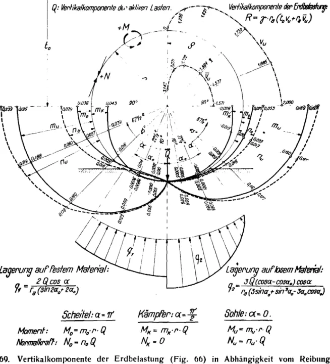
SoleiVertical-Components of the earth loading (Figo66) 1n dependence
of the friction angle 0 {Curves on the upper right quarter)o
Inner forcsa due to radial distribution of the support reactlonso
in dependence on the support angle 0
Support on firm materialo Support on loose material (right curves)
laserung auffeslem Malerial: 2Qcos cr セ
=
ri/(sin2«of'2ao) Sche/fel:Q'"'It Momen!: Mo=mo',,'Q NottfT18/kPaH:No -
not(Kampfer:a:"'f
MI( '" mK · (' ·q
NI( '" 0•
• Lagerung auf.osemHaleffal: = 3Q(COSa-C03rro)cosaセR HGゥQHjウゥョ。dNLNウ[ョセオLLMj。ッ」ッウ。j
Sohle:C(=o.
Mu'C mu·r·o
Nu • nu·QFig. 69. Vertikalkornponente der Erdbelastung (Fig. 66) in Abhangigkeit vom Reibungs-winkel
e.
(Kurven am oberen Viertel rechts)Innere Krafte infolge Verteilung r ad i a Je r Auflagerreaktionen, in Abhangigkeit vom Auf-lagerwinkel Uo'
(Tension stress
positive)
"
MAXIMUM STRESS" ACCORDING TO LAME9 AT THE INNER SIDE OF THICK<=> \'ALIED PIPESo
8
b
セWHjHjL umaxセ = a-
---r - .
Pi·ri b -(5-Pa·ra rrZugspannungl?npoS/l/v)1.00 0,.90 ! l- ---¢i ---セ
L---- -.- - - ...
¢a 0.70 0.80 ¢i ... !..l.rv
- . '1a ra 0.00 (fJ00L...-_--L_ _...L.-_--4._ _-'--_.--L_ _- L -_ _1--_---l.-_ _NNjNNM⦅セ 0.50 セNjoo _ _セOLRORM
1,2001---O=-r-'
/ + a. ra uooセMMMMM - MMMMMセMMFlgo 6
Earth over tillings Spec11'lc Weight
inner friction angle
natural
angle
ot repose
0Stress condition according to
RanKine tor large overftlling height
CroWlli
Abutments
Soleg
-Coetficients
for the present authoritative
support angle
Support on
エャセSupport on loose
material
material
Support on
firm materialo
Support on
loose materialo
PIpe in
wIde tillIng
Load increases due to
stronger compressiblllt7
ot wide tilling are to
be
kept in m1nd
oPipe in Trench
Friction angle on
the trench
walloFormulas and coetticients tor the simplified pipe computationso
iョョ・セ
forces due to distribution
ot the vertical
イ・。」ᄋゥッョセin dependence
is tor rigid pipe still to
beIncreased by the supplementary pressure
compressibility
ot the fIl11ngo
on the· support angle
(Figo
I.
due to the
B.
,.Rohl'8In Uf'aben. ー⦅セセセヲヲャIHQ⦅・Mセ 3P ,A of-2TT'R2cosf' k=tao' f-sln,p p'rvO ,JJ QKウQョセ I irvf:Relbungsw!nkel antJert(JrabenwanOul7f/ • セN I I . I I I92 '
, ' , ' , ,. Lagef'ung aufosemMalt1f'ial:
a = Jpsosa.(1- sセGョR|x ) 72 2SlnQ" sm2a:."
to
Mセセ
i0rv-lcos
e«
soaLagef'uny auf resfem MateriElJ.. セ coso:
9t=
P
sina:"ErrdubeftschUflung: Raumgew!chfT,lnI7E'f'tJf'RelbungswlnkeINn:ro1'l.8Oschungwlnkelg. Scheffel: M=-'O,o80r(fifW)-fl2{f4299p-a229p'l+(BfW+2pl')r'l1+N1f"R
M!J?3t/?/W7)' ; . ,·/.····f//,."·'·.· ..." 1I ' · . .: . • . . .' //.. '/'/"/'/'.,'. ..)). z')' 7 ./,////•. /"./ •... /777';".' .// N -- -0.0.'006, 0 ' -a"'42W,C' -flOGッNャiiセ n9,lr7,II /r- 1.1" .1 セm
l"furlp-",.OJJp/+lufrrf,cpt'/r'l2 f T
Spannungszusfand nach RBnkineful'
grosse
Obet'schUHurrPhohen N 5'p+p! セN I P..:..E... '
Kampfer:
M=+ao9/I'(fifW)+fl'{4J07p-a224p?-(fi+Wf2pt')rrz,+N12C'0:-
2 + 2 COS21 'l;;e 2 sIn2q N]エGoLRUPヲゥM。PXXwKーャGKjセ,
t
セ
Sohle: M--'O,2J9r(fifW)-fl2(M87p-a/8sp')+(fi+W+2pl')r'lI+N,f:
N =+'0,0806- 'O,JgaW+fl{'O,IOoP+4S47p1-(f]+ W+ 2pfl)r'l2+
J::'
Be/werte
rz
fUr denjewe/Is mas$gebenden Auflagerwinkel
a
o :L-agerung -auftesfem Maferial. I Lagef'ung auf/osem Material,
a02
t
"S ⦅セYヲスセ セ ,!"SO"--0,015 - '1.1 • NNNNNNNNNNNNセOゥ |セ 'If nzセ
61'fz"'y
/'! '\セ セVL^セセ
N⦅セG|N|ッNセセ
}.;.,
セLj⦅ーH|セ
セッN
@/,1, W". 'I.. .. ᄃNセ .1 .1 セ ';:\ セ セGBZャ a.:f§セ c:r'70OS-o HG|セ,\; / . liiSl I' セ 9q" セセNセ 1".セ
'"
セ セ セセA
A . R-adrJlV.JCkCt.,
Rohre
in
welte"Aufschufhl%' I I3P •
P=Tt r2rr RP cosfJ
P'= r(tffl) 1+1-si'!gsing
セ・ャ。ウャオセアウウャ・ャァ・エGオョァ・ョ
mf0lgesl8rkerefl
ZUSammen-druckb8rkelf welleI'5chUllun-OセN
gen sindlUberuckslchHgen,
Formeln und Koeffizienten fur die vereinfachte Rohrberechnung.
Innere Krafte infolge Verteilung ve r t i k a I e r Mlflagerreaktionen, in Abhiingigkeit vom Auflagerwinkel ao
fJ ist fiir s t a rr e R0h re noch um den Zusatzdruck .I q (Fig. 68), infolge Zusammendriickbarkeit der Schtittung ZlI vergroBern
Figso 7 and 8
Section sセ Ordinates positive
outwards Section S: Ordinatespositive
outwards
Influence lines tor the elastic bedding on the radially loaded
ーゥー・セ Charactertistic of the deformability
Generally valid influence lines for the inner
forces on the radially
Schm'lfs: !I-I'J·ZP,'lo
p-ky
p r'!k ET-71 Ordinatenposif/v nachaussen -8 g - 2'IOcm S p - 2"O-'kglcm 2 I P k= IOkg/cmJSchnitt S:
M=r,ZP"b
q
-EP.rz2
N- Zp.",
Ord/nalen'l
po51liv f1JCh
Bussen.
'l, -
0,1cmkg
'b -
0,1kg
'2s --..
(J,1kg
P
EinfluBlinie fur die elastische
Bettung
am radial belasteten
Rohr-Charakteristik
der
Verformbarkeit:
1i".7
Al1gemein giiltige EinfluBiinien ffir die
inneren Krafte am radial belasteten Rohr
•
a
U) u
Flgo 9
Filling llatl'rial
, 0
セ
Rigid Pipe
Deflection line of the pipe wall exclusion ot vertical translation
Support positive outwards. Elastic pipe.
EARTH LOADING AND STRESSING OF AN IRON PIPE OF 66 cmo
fliegellflle del'ROhr -wandun,g ausscn/;ess/icn lIertikal - li'anshllon ·1 r4.k=O £.J SlarresHoll!' rrrn i.11111111/11111111111111111111111111111111111111111i ll n Scnultungsmalel'lal.· o]セXUZ /'773
9-
=J5° セ = lokglcm,]"
--
/
I:
\
\
. ' \ .. N ---1?J.oK'!/lcm' ... I " セBBn . , l- '-WセOtM
I :
(82kg/0"2I
! Aul'lragungenposillv nacheosse»
I セ
I
r
·k =7/£.J
I 7 .,., 2 lIaslisches Hohr
2,8 "!Item
Erdbelastung und -Beanspruchung cines Eisen-Rohres von 66 em Durehmesser unter einer Obcrschiittung von 6 m
o S o o "'ltI A ,
..,
0 .c: セ PI セ'5
セ CD Jot セ '-4 o8
... rot CDセ
5J
Fig. 10
Inns" friction
angle I : 35°Specific Weight
3
= 10 8 5tim
Concrete Sole
......