HAL Id: hal-01520388
https://hal.archives-ouvertes.fr/hal-01520388
Submitted on 10 May 2017
HAL is a multi-disciplinary open access archive for the deposit and dissemination of sci-entific research documents, whether they are pub-lished or not. The documents may come from teaching and research institutions in France or abroad, or from public or private research centers.
L’archive ouverte pluridisciplinaire HAL, est destinée au dépôt et à la diffusion de documents scientifiques de niveau recherche, publiés ou non, émanant des établissements d’enseignement et de recherche français ou étrangers, des laboratoires publics ou privés.
Distributed under a Creative Commons Attribution - ShareAlike| 4.0 International
Laguerre–Gaussian modal q-plates
Mushegh Rafayelyan, Etienne Brasselet
To cite this version:
Mushegh Rafayelyan, Etienne Brasselet. Laguerre–Gaussian modal q-plates. Optics Letters, Optical Society of America - OSA Publishing, 2017, 42 (10), pp.1966 - 1969. �10.1364/OL.42.001966�. �hal-01520388�
Laguerre
–Gaussian modal q-plates
M
USHEGHR
AFAYELYAN1,2 ANDE
TIENNEB
RASSELET1,2,*
1Univ. Bordeaux, LOMA, UMR 5798, F-33400 Talence, France 2CNRS, LOMA, UMR 5798, F-33400 Talence, France
*Corresponding author: etienne.brasselet@u bordeaux.fr
We propose space-variant uniaxial flat optical elements designed to generate pure Laguerre–Gaussian modes with arbitrary azimuthal and radial indices l and p from an in-cident Gaussian beam. This is done via the combined use of the dynamic and the geometric phases. Optimal design pro-tocol for the mode conversion efficiency is derived, and the corresponding characteristics are given for 6 ≤ l ≤ 6 and 0 ≤ p ≤ 5. The obtained “modal q-plates” may find many applications whenever the radial degree of freedom of a light field is at play.
OCIS codes: (140.3300) Laser beam shaping; (050.4865) Optical vortices.
Laguerre Gaussian (LG) beams represent a well known orthogonal basis for the scalar paraxial Helmholtz equation [1], each mode being associated with a pair of indices, l and p, that correspond to two independent transverse degrees of freedom. The azimuthal index l is an integer related with the orbital an gular momentum carried by a LGlpbeam, namely lℏ per pho
ton along the propagation direction [2]. This property has given to the LG beams a prime position in the optics of vortex beams for 25 years. The radial index p≥ 0 is an integer asso ciated with the transverse intensity distribution of the light field. Omitting the propagation factor exp!i"k0z ωt#$, where
k0is the wavenumber, z is the coordinate along the propagation
direction, ω is the angular frequency, and t is the time, the complex electric field amplitude Elpof a LG mode in vacuum
is expressed in the cylindrical coordinate system "r; ϕ; z# as [1] Elp"r;ϕ;z;w0# % Clpw"z#w0 !r 2p w"z# #jlj Ljlj p $ 2r2 w"z#2 % exp ! r2 w"z#2 # × exp & i ! k 0r2z 2"z2& z2
0#& lϕ "2p & jlj & 1#arctan
$z z0
%#' ; (1) with Clpa constant that can be derived from the beam power
expression, P %1 2ϵ0c
R R
jElpj2rdrdϕ, where ϵ0 is the dielec
tric permittivity of vacuum, and c is the speed of light in vacuum. In addition, Ljlj
p"x# %Ppk%0"jlj&k#!"p−k#!k!"jlj&p#! " x#krefers
to the associated Laguerre polynomials, w0 is the beam
waist radius, z0% k0w20∕2 is the Rayleigh distance, and
w"z# % w0 1 & "z∕z0#2
p
.
There is a substantial gap between the studies related to the azimuthal versus radial degrees of freedom of LG beams. Nevertheless, several works have already emphasized the impor tance of the radial modal content. From a quantum point of view, an operator formalism for the radial modes has been es tablished [3 5]. It has also been shown that optical information protocols may benefit from the radial degree of freedom [6 8]. The role played by the radial features of a light field within the classical picture has also been explored, for instance regarding its diffraction properties [9], but mainly in the context of the creation of pure LG modes. Contactless optical manipulation is another classical optics application example, where the super position of LG modes including at least one high order radial mode is used to create rotating beams [10,11] or so called bottle beams [12]. In practice, numerous techniques have been intro duced to produce light beams with a well defined azimuthal index l, such as diffractive optical elements [13], computer generated holograms [14], refractive spiral phase plates [15], optical cavities [16,17], or geometric phase optical elements [18], though origi nally restricted to the generation of LGl0like vortex beams.
This has been generalized to high order radial modes with p≥ 1, for instance by using phase shaping via single high order diffractive optical elements [19], computer generated high order phase holograms [20], high order spiral phase plates [21], high order geometric phase optical elements [22], or amplitude only spatial light modulators [23]. Remarkably, complex amplitude modulation can be mimicked by phase only optical elements. This can be used to generate free space highly pure LGlpbeams [24,25] as well as other kinds of beams,
for instance bounded Bessel beams or Hypergeometric beams [26]. Nevertheless, there is a practical tradeoff between accu racy and efficiency, which are competing characteristics. An in tracavity high order complex amplitude modulation approach has also been developed [27]. In this context, the advent of powerful coherent integrated optical sources with controlled azimuthal and radial indices should emerge, with a huge range of practical uses in optical communications, optical imaging, optical trapping, or optical manipulation.
Here we propose another route to achieve complex amplitude modulation via the combined actions of the dynamic and geometric phases, towards the generation of pure LG modes
with arbitrary indices l and p. The dynamic phase is used to encode the desired LG field magnitude profile into one of the two circularly polarized components of the transmitted light, which is retrieved by circular polarization filtering. The geometric phase is then adjusted to provide the desired LG helical phase profile. We stress that pure LG beam shaping of one of the circularly polarized output field component is effective as soon as light emerges from the optical element. Assuming ideal polarization selection, this method thus gets rid of the tradeoff between accuracy and efficiency mentioned above.
We consider a slab of inhomogeneous anisotropic medium where both the optical axis orientation angle ψ and the birefrin gent phase retardationΔ are space variant in the transverse plane of the optical element with thickness L and input facet located at z % 0. We consider an incident circularly polarized paraxial Gaussian (LG00) beam propagating along the z axis. From
Eq. (1), its electric field is expressed by Ein"r; ϕ; z < 0; t# %
E00"r; ϕ; z; w0;in# exp!i"k0z ωt#$cσ where cσ%"x &iσy#∕ 2p
with σ % '1 referring to the circular polarization basis. Neglecting diffraction effects inside the slab, the output light field at z % L can be straightforwardly obtained by applying locally the Jones formalism [28]. This gives for the output field, up to an unimportant phase factor exp!i"k0n⊥L ωt#$ where n⊥ (taken
as constant without loss of generality) is the refractive index perpendicular to the optical axis,
Eout"r; ϕ; L# ∝ exp ! r2 w2 0;in& i Δ"r; ϕ# 2 # × & cosΔ"r; ϕ# 2 cσ& i sin Δ"r; ϕ# 2 exp!i2σψ"r; ϕ#$c−σ ' : (2) In the case of a uniform birefringent phase retardationΔ % π and azimuthally varying optical axis orientation ψ % qϕ with q half integer, Eq. (2) simplifies to the known case of a “q plate,” which refers to a pure geometric phase optical element enabling the generation of an optical vortex with polarization dependent azimuthal index l % 2σq [29]. However, since a q plate is im printing a phase only modulation of the form exp"ilϕ#, the out put light field is a superposition of a large number of LG modes with high order radial indices [30]. Our idea consists of exploiting the interplay between space variant dynamic and geometric phases in order to perform complex amplitude modulation in the circular polarization basis specifically, by introducing appropri ate radial dependence for both the birefringent phase retardation and the optical axis orientation of q plate. Namely, accounting for the structuring upgrade π →Δlp"r# and qϕ → ψlp"r; ϕ#, here
after we demonstrate that pure LGlp modes can be generated.
Such a “modal q plate” produces a σ polarized LGlpbeam if
the following condition is satisfied:
Eout"r; ϕ; L# · c(−σ ∝ Elp"r; ϕ; 0; w0;out#; (3)
where the asterisk denotes complex conjugation. The corre sponding expressions forΔp;land ψp;lare derived from Eqs. (1)
and (2):
Δlp"r# % 2 arcsin
$ jE
lpj"r; w0;out# exp"r2∕w20;in#
max
r !jElpj"r; w0;out# exp"r 2∕w2
0;in#$
% ; (4) which implies that the ratio ζ % w0;out∕w0;inbetween the waist
radius w0of the LGlpmode and that of the incident Gaussian
beam satisfies 0≤ ζ ≤ 1 in order to ensure a finite value for the maxr!·$ operator, and
ψlp"r; ϕ# %σ 2 $ lϕ Δlp"r# 2 % π 2 $ 1 H ! Ljlj p $ 2r2 w2 0;out %#% ; (5) where we introduced the unit step function defined as H"x ≤ 0# % 0 and H"x > 0# % 1. By doing so, the birefrin gent phase retardation is always positive and transforms the incident Gaussian intensity profile into that of the desired LGlp mode while the optical axis orientation profile ensures
a purely helical wavefront at the output of the modal q plate. As expected from the Laguerre Gaussian apodization of the incident Gaussian beam, only a fraction η of the incident power is transformed into a given LGlp mode. From Eq. (2), and
accounting thatR∞
0 exp" 2r2∕w20;in#rdr % w20;in∕4, the modal
efficiency is thus expressed as
ηlp % 4 w2 0;in Z ∞ 0 sin2!Δ lp"r; ϕ#∕2$ exp" 2r2∕w20;in#rdr: (6)
From Eqs. (4) and (6), it can be shown that ηlpdepends only
on the waists ratio ζ; see Fig.1for 1≤ l ≤ 3 and 0 ≤ p ≤ 2. The optimal value ζopt
lp that maximizes the modal efficiency
ηoptlp % ηlp"ζoptlp #, and the latter value itself, both depend on l and p. The results are summarized in Tables 1and 2 for
6≤ l ≤ 6 and 0 ≤ p ≤ 5.
Interestingly, the modal problem has a simple analytical solution when p % 0. Indeed, in that case, Eqs. (4) (6) are respectively expressed as
Fig. 1. Modal q plate efficiency as a function of the reduced LGlp
beam waist w0;out∕w0;infor jlj % 1 (black curves), jlj % 2 (red curves),
and jlj % 3 (blue curves), in the case p % 0 [panel (a)], p % 1 [panel (b)], and p % 2 [panel (c)].
Δl0"r# % 2 arcsin !$ 2 jlj s r W %jlj exp $ r2 W2& jlj 2 %# ; (7) ψl0"r; ϕ# %σ 2 $ lϕ Δl0"r# 2 % ; (8) ηl0% ζ2jlj! !e jlj"1 ζ 2# #jlj ; (9) where we have introduced the effective waist radius
W % w0;in ζ
1 ζ2
p : (10) This gives the following expressions for the parameters of optimal modal q plates:
ζoptl0 % 1 1 & jlj p ; (11) ηopt l0 % jlj!e jlj "1 & jlj#1&jlj: (12)
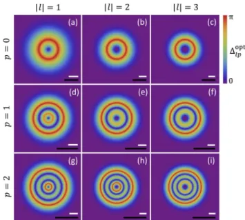
For the sake of illustration, the maps of the optimal bire fringence phase retardationΔopt
lp "r# and optical axis orientation
angle ψopt
lp "r; ϕ# are shown in Figs.2and3for 3≤ l ≤ 3 and
0≤ p ≤ 2. The visual inspection of these maps allows grasping the fabrication challenge towards the practical realization of modal q plates. Indeed, to date, the various technologies used to engineer q plates are basically implemented within a scheme of planar slabs exhibiting a constant birefringent phase retarda tion. For instance, one can mention liquid crystals [31] or pol ymer liquid crystals [32] photoalignment technologies that deal with the structuring of truly birefringent media. There are also strategies based on form birefringent media, where the effective optical anisotropy emerges from subwavelength structuring of isotropic materials, such as femtosecond laser structuring of glasses [33] or polymers [34], nanofabrication enabled struc turing of metals [35] or dielectrics [36]. In the former case, it is very challenging to consider the independent local control
of both the birefringent phase retardation and the optical axis orientation, although arbitrary in plane optical axis patterns at fixed retardance can nowadays be achieved [37]. In the latter case, however, one could consider retardance control at fixed structured thickness via space variant filling factor F"r; ϕ# of a given subwavelength step grating of period Λ, each period consisting of a FΛ width with refractive index n1 and a
"1 F #Λ width with refractive index n2, which lead to an ef
fective birefringence dn that depends on n1, n2, and F. By
doing so, an arbitrary pattern Δ"r; ϕ# can be obtained from the relationship Δ"r; ϕ# %2π
λdn"n1; n2; F"r; ϕ##L. Another
Table 2. Optimal Values ηoptlp of the Modal Q-Plate Efficiency for −6 ≤ l ≤ 6 and 0 ≤ p ≤ 5
jlj ! 1 jlj ! 2 jlj ! 3 jlj ! 4 jlj ! 5 jlj ! 6 p % 0 0.68 0.55 0.47 0.42 0.38 0.35 p % 1 0.48 0.44 0.40 0.38 0.35 0.34 p % 2 0.39 0.38 0.36 0.34 0.33 0.31 p % 3 0.33 0.34 0.34 0.31 0.30 0.29 p % 4 0.29 0.30 0.30 0.29 0.29 0.28 p % 5 0.25 0.27 0.28 0.27 0.27 0.27 Table 1. Optimal Values ζoptlp Maximizing ηlpfor −6 ≤ l ≤ 6
and 0 ≤ p ≤ 5 jlj ! 1 jlj ! 2 jlj ! 3 jlj ! 4 jlj ! 5 jlj ! 6 p % 0 0.71 0.58 0.50 0.45 0.41 0.38 p % 1 0.44 0.39 0.35 0.33 0.31 0.29 p % 2 0.38 0.32 0.29 0.27 0.26 0.25 p % 3 0.34 0.29 0.26 0.24 0.23 0.22 p % 4 0.32 0.27 0.25 0.23 0.21 0.20 p % 5 0.30 0.26 0.24 0.22 0.20 0.19
Fig. 2. In plane spatial distribution of the birefringent phase retardation Δopt
lp"r# of optimal modal q plates for 3 ≤ l ≤ 3 and
0≤ p ≤ 2. White scale bar: w0;out. Black scale bar: w0;in.
Fig. 3. In plane spatial distribution of the optical axis orientation angle ψopt
lp"r; ϕ# of optimal modal q plates for 3≤ l ≤ 3 and
solid state option could rely on the use of space variant anten nas designed to control the complex amplitude of light. In other words, the practical realization of modal q plates is acces sible to state of the art nanofabrication tools.
In addition, self engineered strategies that do not rely on machining techniques can also be considered. Indeed, it has been shown that various kinds of spontaneously formed liquid crystal defect structures enable the generation of an optical vortex beam with spin controlled azimuthal index with the additional key feature demonstrated here, namely Δ % Δ"r# with Δ"0# % 0. One can mention hedgehog defects [38], umbilics [39] and disclinations [40] in nematics, focal conic do mains in smectics [41], and solitonic defect structures in cholesterics [42]. Moreover, liquid crystals are natural can didates for the required twisted configurations of the form ψ"r; ϕ# % lϕ & f "r#, one shown for instance in the case of nematic films under all optical [43] or electro optical [44] exter nal stimuli. That is to say, the engineering of modal q plates could also be considered using soft matter optically anisotropic systems. Recalling that the usual q plates have already found a lot of applications both in classical and quantum optics [45] and are likely to find many others in the future [46], modal q plates enabling the control of both the azimuthal and radial modal content of a light field with a single optical element, possibly integrated [47], should be of interest in many scientific and technological areas. It should be mentioned that modal q plates are designed for a given azimuthal index l that cannot be switched to l by mere flip of the helicity of the incident light field, but flipping also the optical element along the propaga tion axis. Finally, we note that the proposed combined action of dynamic and geometrical phases towards the control of the radial degree of freedom of a light field represents another attempt to tailor the spatial properties of electromagnetic fields by hybrid phase transformations [48,49].
Funding. Agence Nationale de la Recherche (ANR) (ANR 15 CE30 0018).
REFERENCES
1. A. E. Siegman, Lasers (University Science Books, 1986).
2. L. Allen, M. W. Beijersbergen, R. J. C. Spreeuw, and J. P. Woerdman, Phys. Rev. A 45, 8185 (1992).
3. E. Karimi and E. Santamato, Opt. Lett. 37, 2484 (2012).
4. E. Karimi, R. Boyd, P. de la Hoz, H. de Guise, J. Řeháček, Z. Hradil, A. Aiello, G. Leuchs, and L. L. Sánchez Soto, Phys. Rev. A 89, 063813 (2014).
5. W. N. Plick and M. Krenn, Phys. Rev. A 92, 063841 (2015). 6. Y. Zhang, F. S. Roux, M. McLaren, and A. Forbes, Phys. Rev. A 89,
043820 (2014).
7. E. Karimi, D. Giovannini, E. Bolduc, N. Bent, F. M. Miatto, M. J. Padgett, and R. W. Boyd, Phys. Rev. A 89, 013829 (2014). 8. M. Krenn, M. Huber, R. Fickler, R. Lapkiewicz, S. Ramelow, and A.
Zeilinger, Proc. Natl. Acad. Sci. USA 111, 6243 (2014).
9. J. Mendoza Hernández, M. L. Arroyo Carrasco, M. D. Iturbe Castillo, and S. Chávez Cerda, Opt. Lett. 40, 3739 (2015).
10. S. N. Khonina, V. V. Kotlyar, V. A. Soifer, M. Honkanen, J. Lautanen, and J. Turunen, J. Mod. Opt. 46, 227 (1999).
11. S. Franke Arnold, J. Leach, M. J. Padgett, V. E. Lembessis, D. Ellinas, A. J. Wright, J. M. Girkin, P. Ohberg, and A. S. Arnold, Opt. Express 46, 227 (2007).
12. J. Arlt and M. J. Padgett, Opt. Lett. 25, 191 (2000).
13. V. Y. Bazhenov, M. Vasnetsov, and M. Soskin, JETP Lett. 52, 429 (1990).
14. N. Heckenberg, R. McDuff, C. Smith, and A. White, Opt. Lett. 17, 221 (1992).
15. S. Khonina, V. Kotlyar, M. Shinkaryev, V. Soifer, and G. Uspleniev, J. Mod. Opt. 39, 1147 (1992).
16. M. Harris, C. Hill, P. Tapster, and J. Vaughan, Phys. Rev. A 49, 3119 (1994).
17. S. C. Chu and K. Otsuka, Opt. Commun. 281, 1647 (2008). 18. G. Biener, A. Niv, V. Kleiner, and E. Hasman, Opt. Lett. 27, 1875
(2002).
19. S. Khonina, V. V. Kotlyar, R. Skidanov, V. Soifer, P. Laakkonen, and J. Turunen, Opt. Commun. 175, 301 (2000).
20. Y. Ohtake, T. Ando, N. Fukuchi, N. Matsumoto, H. Ito, and T. Hara, Opt. Lett. 32, 1411 (2007).
21. G. Ruffato, M. Massari, and F. Romanato, Opt. Lett. 39, 5094 (2014). 22. P. Chen, B. Y. Wei, W. Ji, S. J. Ge, W. Hu, F. Xu, V. Chigrinov, and Y.
Q. Lu, Photon. Res. 3, 133 (2015).
23. V. Lerner, D. Shwa, Y. Drori, and N. Katz, Opt. Lett. 37, 4826 (2012). 24. V. Arrizón, U. Ruiz, R. Carrada, and L. A. González, J. Opt. Soc. Am.
A 24, 3500 (2007).
25. T. Ando, Y. Ohtake, N. Matsumoto, T. Inoue, and N. Fukuchi, Opt. Lett. 34, 34 (2009).
26. S. N. Khonina, S. A. Balalayev, R. Skidanov, V. V. Kotlyar, B. Paivanranta, and J. Turunen, J. Opt. A 11, 065702 (2009). 27. S. Ngcobo, I. Litvin, L. Burger, and A. Forbes, Nat. Commun. 4, 2289
(2013).
28. E. Brasselet, Opt. Lett. 38, 3890 (2013). In that paper, the misprint “q integer” should be replaced by “q half integer.”
29. L. Marrucci, C. Manzo, and D. Paparo, Phys. Rev. Lett. 96, 163905 (2006).
30. A. Forbes, A. Dudley, and M. McLaren, Adv. Opt. Photon. 8, 200 (2016). 31. S. Slussarenko, A. Murauski, T. Du, V. Chigrinov, L. Marrucci, and E.
Santamato, Opt. Express 19, 4085 (2011).
32. S. R. Nersisyan, N. V. Tabiryan, D. Mawet, and E. Serabyn, Opt. Express 21, 8205 (2013).
33. M. Beresna, M. Gecevičius, P. G. Kazansky, and T. Gertus, Appl. Phys. Lett. 98, 201101 (2011).
34. X. Wang, A. Kuchmizhak, E. Brasselet, and S. Juodkazis, “Dielectric geometric phase optical elements from femtosecond direct laser writ ing,” arXiv:1612.04487 (2016).
35. D. Hakobyan, H. Magallanes, G. Seniutinas, S. Juodkazis, and E. Brasselet, Adv. Opt. Mater. 4, 306 (2016).
36. R. C. Devlin, A. Ambrosio, D. Wintz, S. L. Oscurato, A. Y. Zhu, M. Khorasaninejad, J. Oh, P. Maddalena, and F. Capasso, Opt. Express 25, 377 (2017).
37. J. Kim, Y. Li, M. N. Miskiewicz, C. Oh, M. W. Kudenov, and M. J. Escuti, Optica 2, 958 (2015).
38. E. Brasselet, N. Murazawa, H. Misawa, and S. Juodkazis, Phys. Rev. Lett. 103, 103903 (2009).
39. E. Brasselet and C. Loussert, Opt. Lett. 36, 719 (2011).
40. C. Loussert, U. Delabre, and E. Brasselet, Phys. Rev. Lett. 111, 037802 (2013).
41. B. Son, S. Kim, Y. H. Kim, K. Käläntär, H. M. Kim, H. S. Jeong, S. Q. Choi, J. Shin, H. T. Jung, and Y. H. Lee, Opt. Express 22, 4699 (2014). 42. B. Yang and E. Brasselet, J. Opt. 15, 044021 (2013).
43. E. Brasselet, Opt. Lett. 34, 3229 (2009).
44. R. Barboza, U. Bortolozzo, M. G. Clerc, S. Residori, and E. Vidal Henriquez, Philos. Trans. R. Soc. A 372, 20140019 (2014). 45. L. Marrucci, E. Karimi, S. Slussarenko, B. Piccirillo, E. Santamato, E.
Nagali, and F. Sciarrino, J. Opt. 13, 064001 (2011). 46. L. Marrucci, J. Nanophoton. 7, 078598 (2013).
47. M. S. Seghilani, M. Myara, M. Sellahi, L. Legratiet, I. Sagnes, G. Beaudoin, P. Lalanne, and A. Garnache, Sci. Rep. 6, 38156 (2016). 48. M. Pal, C. Banerjee, S. Chandel, A. Bag, S. K. Majumder, and N.
Ghosh, Sci. Rep. 6, 39582 (2016).
49. Z. Liu, Y. Liu, Y. Ke, Y. Liu, W. Shu, H. Luo, and S. Wen, Photon. Res. 5, 15 (2017).