16)~
Control of the Growth Interface Location and Morphology in
Vertical Bridgman Geometries
by
Satyavolu Srinivas Papa Rao
Bachelor of Technology (Metallurgical Engineering) Indian Institute of Technology, Madras
(1988)
Submitted to the Department of Materials Science and Engineering on May 3, 1996 in Partial Fulfillment of the Requirements for the Degree of
Doctor of Philosophy
at the
Massachusetts Institute of Technology
June 1996
@Massachusetts
Institute of Technology 1996
Signature of Author...
Department of Materials Science and Engineering May 3, 1996 Certified by... August F. Witt Thesis Supervisor Accepted by... Michael F. Rubner TDK Professor of Materials Science and Engineering Chair, Departmental Committee on Graduate Students
,,AS~CHUSEFTS INSi''uTi
OF TECHNOLOGY
JUN 2
41996
Scien-6
( roA IECControl of the Growth Interface Location and Morphology in
Vertical Bridgman Geometries
by
Satyavolu Srinivas Papa Rao
Submitted to the Department of Materials Science and Engineering on May 3,1996 in Partial Fulfillment of the Requirements for the Degree of Doctor of Philosophy in Electronic Materials
Abstract
In conventional vertical Bridgman crystal growth furnaces, the location of the crystal-melt interface with respect to the furnace, and its shape, change during growth. Interface relocation is due to changing thermal coupling between the furnace and the charge during translation of the charge, and it affects the radial dopant segregation, stresses, facetting, increases polycrystallinity, and causes the growth rate to diverge from the translation rate. Interface relocation transients are accentuated, and prevail over the entire course of the run, for short charge lengths. Interface location control was incorporated in the design of a heat-pipe based vertical Bridgman growth system. The temperature at two closely spaced points within the gradient zone is sensed. This information is used by two independant feedback loops to control the heater power in the hot and cold zones, in order to keep the melting point isotherm at a fixed location between the control points. Interface relocation is thus prevented by automatically compensating for transient thermal effects seen in conventional furnaces during growth, through appropriate changes in power input to the heaters.
With a graphite dummy to mimic a crystal charge in the gradient freeze growth mode, thermal field stabilization was demonstrated at typical growth rates
(3 cm/hr). It was shown that gradients as low as 50C/cm could be sustained over conventional crystal growth lengths. Thermal studies (with a BN dummy) in the conventional Bridgman configuration established the importance of gradient zone design and related radial heat fluxes, as well as the techniques for proper
temperature measurement therein. The ability to control the thermal field within the gradient zone at typical growth rates was demonstrated, when the
afore-mentioned control modifications were utilized.
Gallium doped germanium (seeded in the < 111> orientation) was grown in the Bridgman mode, with the temperatures within the gradient zone being stabilized as described above. Growth rate measurements show that, following an initial
Radial and axial dopant segregation measurements showed that a toroidal
convective flow exists near the interface. The interface shape was found to be tilted
by 1.5", but this asymmetry was not noticeably reflected in the radial segregation
behavior. Axial segregation data showed that the keff decreased from 0.1 to 0.083 as the melt aspect ratio shrank from 5:1 to 2:1. An increase in striation contrast was observed along the growth direction. No evidence was seen of extended facet formation at any radial position. Most crystals showed spurious nucleation at the
crucible wall (graphite and quartz). These grains extended into the bulk of the crystal during growth, resulting in polycrystallinity (with fewer than 3 crystallites, typically). The interface demarcation lines were found to be continuous across the grains. The polycrystallinity was found not to interfere with growth or segregation behavior studied in this work.
The support of the Intel Foundation, the National Science Foundation and of the National Air and Space Administration is gratefully acknowledged.
Thesis Supervisor: August F. Witt
Table of contents
Control of the Growth Interface Location and Morphology in Vertical Bridgman Geometries ...
Abstract Acknowledgments ... Chapter 1 Introduction ... ... Chapter 2 2.1 2.2 2.2.1 2.2.2 2.3 2.4 2.4.1 2.4.2 2.4.3 2.4.4 2.4.5 2.5 2.6 Chapter 3 3.1 3.2 3.3 Literature Review ...
The Czochralski technique ...
Bridgman-type furnace geometries ...
The Bridgman-Stockbarger configuration ... Gradient freeze technique ...
Advantages of Bridgman geometries ...
Unresolved issues in Bridgman type crystal growth Thermal fields in the charge ...
Stoichiometry control ... ... Considerations of crucible-melt interactions ...
Interface morphology control ...
Dopant segregation considerations ...
Heat-pipes and their use in crystal growth furnaces Sum mary ... ...
Objectives and structure of the thesis ...
M otivation ... ... Objectives of thesis .... ...
Stages of thesis work ...
Chapter 4 Thermal characteristics of the furnace in the gradient freeze mode ...
4.1 Furnace instrumentation and software features ...
4.2 Furnace hardware features ...
4.3 Thermal characterization of the furnace ... 4.3.1 Reproducibility ... ...
4.3.2 Furnace tuning ... ...
4.3.3 'Gain scheduling' in furnace control ...
4.3.4 Control of the furnace in the gradient freeze mode 4.4 Sum mary ... ...
Chapter 5 Thermal characterization of the furnace in the Bridgman growth mode ...
5.1 Furnace instrumentation and software features ...
5.1.1 5.1.2 5.2 5.2.1
Instrumentation ... Data acquisition and control software ...
Thermal characterization experimental results ...
Influence of conductive elements in the gradient zone
... ,,,..,... ... ,... ... ,°,,o.°°. ,...,... ...
...
...
...
5.2.2 Heat transfer characteristics of the system ... 88
5.2.3 Axial temperature profile for a nominally low axial tem perature gradient... 94
5.2.4 Influence of heater location on axial thermal profiles ... 97
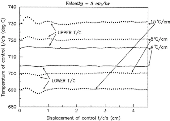
5.2.5 Temperature excursions within the gradient zone ... 98
5.2.6 Temperature measurement within the gradient zone ... 102
5.3 Control of the furnace with gradient zone thermocouples ... 105
5.3.1 Control using one gradient zone thermocouple ... 106
5.3.2 Control with two widely spaced sensors ... 110
5.3.3 Control with two closely spaced sensors ... 110
5.4 Summary ... 112
Chapter 6 Growth of gallium doped germanium in the Bridgman mode of operation ... 115
6.1 General features of growth experiments ... 115
6.1.1 The crystal growth ampoule ... 118
6.1.2 Charge preparation ... 121
6.2 Interface demarcation by current pulses ... 122
6.3 Post-growth analysis procedures ... 123
6.3.1 Sample preparation ... 123
6.3.2 Growth rate measurement procedure ... 125
6.3.3 Spreading resistance measurement procedure ... 126
6.4 Analysis of crystal growth experiments ... 127
6.4.1 Surface features of grown crystals ... 127
6.4.2 Results of growth rate stabilization experiments ... 129
6.4.3 Axial segregation measurements and analysis ... 134
6.4.4 Interface morphology measurements and analysis ... 138
6.4.5 Radial segregation measurements and analysis ... 141
6.5 Summary ... 142
Chapter 7 Conclusions ... 144
Chapter 8 Suggestions for future work ... 147
Appendix A. Spreading Resistance Characterization ... 151
A.1. Introduction ... 151
A.2. Measurement Characteristics ... 153
A.3. Calibration of the Spreading Resistance Probe ... 154
Appendix B. Listing of furnace data acquisition and control program (adc5ver3.c) segments ... 158
B.1 The data acquisition and control program ... 158
B.2 The Parks-McClellan low pass filter ... 158
B.2. The PI control segment of "adc5ver3.c" ... 159
B.3. The segment of "adc5ver3.c" in charge of gain scheduling ... 159
List of Figures and Tables
Figure 1.1 : The Bridgman-Stockbarger system. ... 18 Figure 1.2 : The instrumentation racks ... 19 Figure 2.1: The Czochralski configuration. ... 20 Figure 2.2 : (a) Bridgman furnace, and
(b) Bridgman-Stockbarger furnace. ... 22 Figure 2.3 : (a) Vertical Gradient Freeze and
(b) Electrodynamic Gradient Freeze ... 23 Figure 2.4 : Extended configurational transients in growth rate
in a conventional Bridgman furnace, with different control points and cooling mechanisms[20].
28 Figure 2.5 : Shaped Melt Lowering (after [26]) ... 30 Figure 2.6 : Interface stabilization in a heat-pipe based
Bridgman-Stockbarger furnace (after Wang [27]).
30 Figure 2.7 : Heat flows in (a) convex, (b) planar and
(c) concave interfaces in vertical Bridgman
geometries (after [32]). ... 33 Figure 2.8 : Interface shape - boundary layer interaction ... 34 Figure 2.9: Melt convection cells in a Bridgman-Stockbarger
furnace[44] ... 37 Figure 2.10 : Schematic of the operation of a heat-pipe,
used as a high thermal conductivity device ... 39 Figure 2.11 : Cross-section of a (failed) inconel heat-pipe
from Dynatherm Inc., ... 40 Figure 4.1 : Vertical Gradient Freeze (VGF) Furnace ... 45 Figure 4.2 : The 'gradient freeze mode' of operation of
the modified furnace ... 46 Figure 4.3 : Sample temperature data, showing extent of noise
aliased into low frequency region of the spectrum.
48 Figure 4.4 : Flow-chart for "adc5ver3.c" , the data acquisition
and control program ... 50 Figure 4.5 : The Bridgman- Stockbarger furnace ... 51 Figure 4.6 : Furnace with model (graphite) charge and control
thermocouples moving through furnace bore ... 53 Table 4.1 : Properties of POCO graphite ... 54
Figure 4.7: Reproducibility test results ... 57
Figure 4.9 : Control parameters change due to thermocouple motion. .... 59
Figure 4.10 : Control of the furnace in the gradient freeze mode -influence of the gradient on control performance. ... 61
Figure 4.11 : Control of the furnace in the gradient freeze mode -influence of translation velocity on control performance. ... 62
Figure 5.1 : Vertical Bridgman crystal growth with conventional temperature control ... ... ... ... 63
Figure 5.2 : Vertical Bridgman crystal growth with modified temperature control ... 64
Figure 5.3 : Layout of PCB-1, a custom I/O board. ... . 66
Figure 5.4: Circuit diagram for PCB-1 ... 67
Figure 5.5 : (a) Thermocouple data channel sampled at 100 kHz (sensor at room temperature). (b) Fourier spectrum of unprocessed data, showing low noise characteristics. ... 68
Figure 5.6 : Circuit diagram and layout for PCB-2 ... . 70
Figure 5.7: PCB-2 transfer characteristic ... 71
Figure 5.8 : Oscilloscope traces of samples of the current pulses. ... 72
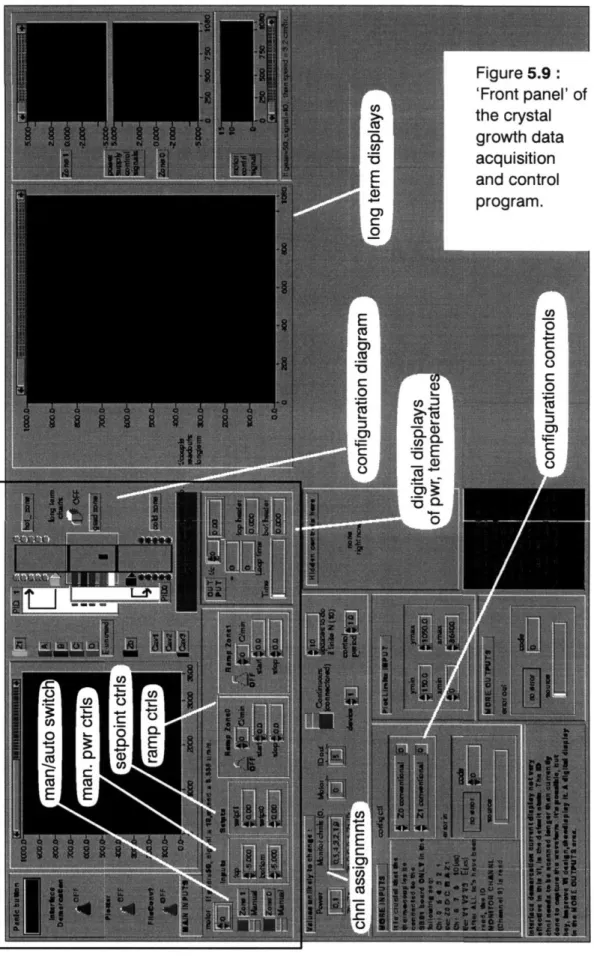
Figure 5.9: 'Front panel' of the crystal growth data acquisition and control program ... ... 74
Figure 5.10: Segment of 'Block Diagram' of Labview control program .. 76
Figure 5.11 : Setpoint step response of the temperatures of (a) bottom heat-pipe, and (b) top heat-pipe ... 77
Table 5.1 : Selected properties of hot-pressed boron nitride (grade HBC) 78 Figure 5.12 : Boron nitride rod used for thermal characterization. ... 79
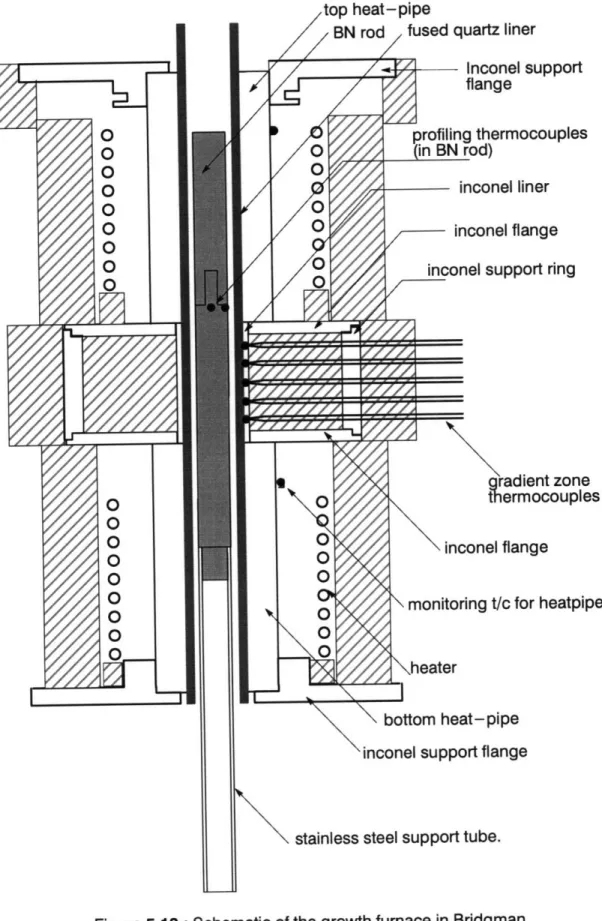
Figure 5.13: Schematic of the growth furnace in Bridgman mode of operation ... 81
Figure 5.14 : (a) adiabatic (fully insulating) gradient zone, and (b) 'diabatic' gradient zone (after [27]) ... 82
Figure 5.15 : Gradient zone structure ... 82
Figure 5.16 : Axial thermal profile, and radial temperature gradients, in the Bridgman furnace using an inconel-lined gradient zone. .. . 83
Figure 5.17 : Gradient zone fabricated only of insulating material... Figure 5.18 : Axial thermal profile, and radial temperature
gradients, with a purely insulating gradient zone. ... 85 Figure 5.19: Schematic of radial heat flows caused by inconel
elements in the gradient zone ... 86 Figure 5.20 : Thermal profiles generated at different speeds of
translation of BN rod ... 87 Figure 5.21 : Response of surface and center thermocouples in
model (BN) charge to step changes in setpoint. ... 89 Figure 5.22 : Resistance network model of the charge, the heat-pipes
and the gradient zone, and coupling through gas. ... 91 Figure 5.23 : Simulation results (with and without inconel liners). ... 93 Figure 5.24: Thermal profile with a low nominal axial temperature gradient ...
95
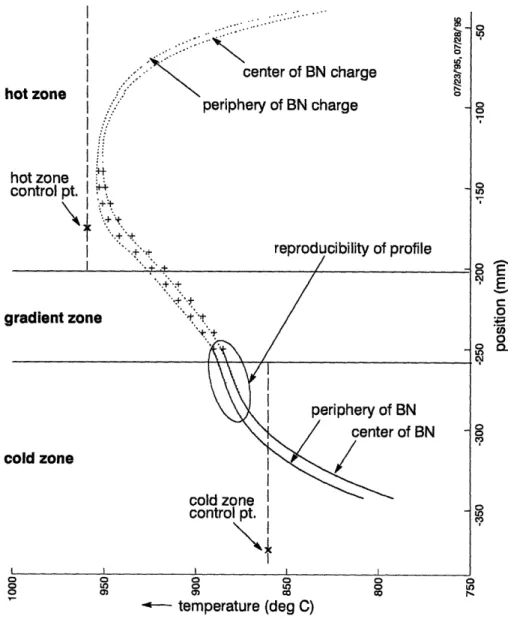
Figure 5.25 : Radial temperature gradient across the gradient zone ... 96 Figure 5.26 : Schematic of the furnace, showing the BN rod with two
thermocouples, the gradient zone with its thermocouple locations, and the location of the heaters relative to
the heat-pipes. ... 99 Figure 5.27: Axial profile with the top zone heater located 25mm
above the top of the gradient zone. (cf: Figure 5.28) ... 100 Figure 5.28 : Axial profile with the top zone heater located directly
on top of the gradient zone. (cf: Figure 5.27) ... 101 Figure 5.29: Records of the gradient zone thermocouples during
translation of the longer BN charge. ... 102 Figure 5.30 : Records of the gradient zone thermocouples during
translation of the shorter BN charge ... 103 Figure 5.31 : Geometric configuration of gradient zone thermocouples .. 104 Figure 5.32 : Fortuitous temperature agreement, with insertion of
gradient zone sensors as in Figure 5.31(b). ... 106 Figure 5.33 : Temperature discrepancy with insertion of gradient zone
sensors as in Figure 5.31(b), at higher axial temperature gradients 107 Figure 5.34 : Control using one gradient zone sensor and
Figure 5.35 : Power requirements of the two zones, for control
using one gradient zone sensor, in Bridgman mode ... 109 Figure 5.36 : Power requirements for control using two widely spaced
gradient zone sensors ... 111 Figure 5.37: Control in the Bridgman mode, using two widely spaced
gradient zone sensors ... 112 Figure 5.38 : Power requirements of the two zones, for control
in the Bridgman mode with two closely spaced sensors ... 113 Figure 5.39 : Control with two closely spaced sensors. ... 114 Figure 6.1 : Picture of the active regions of the furnace, with
surrounding support structure ... 116 Figure 6.2: Scale drawing of the furnace (dimensions in mm)... 117 Figure 6.3: Growth ampoule design ... 118 Figure 6.4 : The first BN support rod design, showing the brittle fracture,
and showing the grooves used for electrical feedthroughs. ... 119 Figure 6.5 : X-ray fluorescence spectrum of Pt lead wire used in ampoule. 119 Figure 6.6 : The second design of (a) BN support rod (b) graphite melt
electrode, and (c) graphite seed electrode, and (d) assembly .... 120 Figure 6.7 : Graphite mold used for casting the (polycrystalline)
germanium charge. ... 121 Figure 6.8 : Sectioning of the grown crystal. ... 123 Figure 6.9: (a) As polished surface and (b) etched surface, when the
polishing action is not'tapered off'. . ... 124 Figure 6.10 : Interface demarcation lines, along with impact trace
of a spreading resistance analysis. ... 125 Figure 6.11 : Schematic of potential distribution in single point
spreading resistance measurements ... 126 Figure 6.12: Surface of as-grown crystal, showing bubble distribution .. 128
Figure 6.13: Schematic of the denuded zones observed around
the larger bubbles ... 129 Figure 6.14 : Temperature readings of the two control sensors
during growth in the Bridgman mode of operation. ... 130 Figure 6.15 : Measured growth rate vs distance grown ... 130
Figure 6.16: Interface relocation as a function of length of crystal grown. 131 Figure 6.17 : Temperature readings of the two control sensors during
growth in the Bridgman mode of operation ... 132 Figure 6.18 : Measured growth rate vs distance grown ... 133 Figure 6.19: Gradient zone excursions, and non-steady growth rate
seen for furnace control in the conventional fashion. ... 135 Figure 6.20 : Axial segregation in the Bridgman mode of operation,
compared with the limiting cases of purely diffusive
and fully-mixed transport. ... 137 Figure 6.21 : Evolution of interface morphology along the
growth direction, at the seeding end . ... 140 Figure 6.22 : Radial segregation profiles (and calculated profiles,
assuming diffusive transport) ... 143 Table A.1 : Spreading resistance calibration sample information ... 156
Acknowledgments
I would like to thank Professor Witt for guiding me so skilfully over the years. I am still amazed at how patiently he worked to educate me - and how optimistic he has been that I would become a productive member of the research fraternity. I have the duty to always produce research of high enough quality, and of improving over time, to ensure I remain counted as one of the students he has advised. I hope always to apply the principles that he has taught me to bring to research - meticulousness of experiment design, thoroughness of preparation,
"parallel processing" of research ideas, fertility of imagination, elegance of presentation, and wry humor. I have yet to figure out his uncanny ability to divine what I was thinking just by looking at me - that would be useful gift to have! I thank Professor Kimerling, and Professor Mikig for being on my thesis committee and giving me the benefit of their expertise, and particularly for being so patient with me!
I would also like to thank Dr. Manfred Lichtensteiger for appearing magically when my spirits hit their lowest spots, and just as magically helping me out of the doldrums. It was instructive to watch his lightning mind at work - anticipating problems keenly or solving them elegantly. Dr. Piotr Becla is another person who has inspired me over the years with the way he works miracles in the lab. I wish I had started working closely with him right from my first day at MIT. Someday, I hope, I too will have a lithography setup in my basement! Dr. Shahryar Motakef is a person who somehow radiated camaraderie toward graduate students even though he was a professor at MIT - I do thank him for all his advice, the energetic discussions we had, and for the depth of his concern over my progress.
Dr. Xuezhong Cao, Dr. Doug Carlson, Dr. Craig Counterman, Dr. Chenting Lin, and Dr. Michael Wargo have all helped me so much in so many ways over so many years that I do hope they don't expect me to requite even a fraction of the debt I owe each of them!
I don't have enough words to express my regard for Ms. Gloria Landahl. She had the most untiring ear for all my songs of despair, and was the most
uncomplaining recipient of my hurrahs when things went well. I also have to thank her for taking the time to teach me American pronunciation, for introducing me to my first Thanksgiving, to cats and New England - not that they go together, even if it might seem like it to my foreign eyes. I would also like to thank John DiFrancesco for all the help he has given me - in spite of my seeming efforts to foil him at his task, with mistakes in my drawings and so on. His (off-!)Broadway renditions made life, shall I say, interesting?
My roommates, John Paul Mattia and Thomas Lee, have borne the brunt of
many troubled, 'Pops-is-talking-in-his-sleep-again-#@&%!*", nights - and are kind
enough to remain my friends! They and Richard Stone are responsible for teaching me about music, and how books ought to mulled over. Richard can rest easy knowing that he has talked the last vestiges of liberalism out of me. I thank David &
Lynn Chalfoun, their cats, Kirsten Bremke, and JP, among others, for making me such a part of their families, even. My cousins, Anupa & Ashutosh Rao, and my
undergrad friends, V. Mahadev and S. Karthik took able care of the long-distance therapy-for-Papa Rao department. Ashdown House, Tan Trinh, and my other fencing pals, Huey Pin Ng, Yee Chuan Koh, Beethoven Cheng, and other
badminton friends, Brad and Lam Bauman, Anil Chakravarty, Karin Ellison, Jim Foresi, Laura Giovane, Diane Ho, Prof. Vernon & Beth Ingram, Young-Chang Joo, Shane &JeeHoon Krska, Serena Losonczy, Josephine Louie, John Matz, Kathy Misovec, Charles Pieczulewski, Srikanth Samavedam, Julie Tsai, Anne Townes, Yu Zheng - they made the years so interesting. I know I haven't made a dent in the list of friends that are so important to me - but I hope to be forgiven for stopping here, and thanking them in person later.
I thank Daphne Png for all the friendship she is so kind to bestow on me, and for the warmth, sweetness and light she radiates to all around her. Her smiling,
level-headed nature has been a wonderful and steadying influence, for which I am very thankful.
I thank my parents, Shri. Seshagiri Rao and Shrimati. Ratnamala, for bringing me up so expertly, against all odds! I thank my brother, Devesh, for his love and support, and for his forbearance in not telling me I seem to be taking forever to get my Ph.D. I am blessed to have parents and a brother such as they!
I thank God for everything.
The support of the Intel Foundation (through the Graduate Fellowship Program), the National Science Foundation (NSF), and of the National Air and Space Administration (NASA), which supported this research continuously, through thick and thin, is gratefully acknowledged.
Chapter 1 Introduction
In this Introduction, the importance of crystal growth to substrate properties and ultimately to device performance is adumbrated. The crystal-melt interface is an important crystal growth parameter. The mechanics of how the interface impacts crystal properties are
outlined, and the benefits to be gained by controlling its location and shape are presented.
Crystal growth techniques have been around for so long, it seems incongruous that, as recently as 1963, a book could bear the title "The Art and Science of Growing Crystals"[1]. While it might have been true that, at that point of time, empirical approaches to crystal growth were dominant, the microelectronic revolution, with its relentless drive towards scaled-down device dimensions, has since spurred intense research into the science of crystal growth. It is hoped that this thesis will be considered a contribution towards narrowing the gap between theory and experiment that still exists.
As device dimensions approach (and even exceed) defect dimensions, a device is more likely to be fatally affected by the presence of a defect. Hence, as device dimensions have shrunk, defect tolerances in chip fabrication have been lowered, to maintain high chip yields. A semiconductor wafer that has been sliced from the boule will find use either as a substrate for the epitaxial growth of active
layers (within which devices are fabricated), or it may have devices fabricated directly on its surface (by ion-implantation, as in GaAs monolithic microwave IC fabrication). If the devices are fabricated in an epilayer, it has been found that
defects in the substrate - threading dislocations, for example - propagate into the
epilayer. It has to be kept in mind that, while the use of an epilayer places the devices in a layer grown with better property controls, it increases the cost of the chip. So, it would confer a competitive advantage to a manufacturer whose crystal growth technology is able to produce wafers of high enough quality not to need epilayer growth prior to device fabrication. If the device fabrication proceeds
without an epilayer being grown, the substrate properties - resistivity, dislocation density, trap density and so on - are clearly important.
The influence of defects on device performance is well-documented. The presence of dislocations in the GaAs substrate affects the threshold voltage of nearby MESFET's[2], causing problems in chip yield. Oxygen content of silicon wafers needs to be controlled, for optimal results to be obtained through the intrinsic gettering process, where a denuded zone is formed at the top surface of the wafer, and fine oxide precipitates (gettering sites) are formed throughout the bulk of the wafer. The oxygen content of the wafer has to be within certain limits to increase resistance of the wafer to warpage during processing (the strengthening comes both from solution hardening and from dislocation pinning at the
precipitates). Oxide precipitates, 'swirl'[3] and 'haze' defects in silicon wafers can be nucleation points for oxidation-induced stacking faults (OISF's). Trace levels of metal contamination increase leakage currents across junctions and adversely affect the behavior of DRAM chips, for example[4]. Point defects and clusters of point defects affect the minority carrier lifetime - the thermal history that the crystal experiences affects point defect density and distribution. Resistivity variation across the diameter of a silicon wafer needs to be controlled (typically, to less than 10%). Changes in dopant segregation from wafer to wafer are also undesirable, from the quality control standpoint. Random fluctuations in dopant concentration on the microscopic scale on a wafer can have deleterious effects on chip yield.
The origins of the various defects during crystal growth need to be understood, if the formation of defects is to be controlled. Considerable understanding has been gained over the past 15 years, about dislocation generation during crystal growth and cool-down. The availability of high
performance computing has made it possible to employ extensive finite element models to study convection patterns in the melts of different crystal growth techniques, and to understand the nature of radial and axial segregation, and of
microsegregation. In GaAs crystal growth, the influence of melt stoichiometry and other crystal growth parameters on the distribution of the EL2 defect, and on implant activation behavior is being understood more clearly. Still, there are many unanswered questions in the science of crystal growth. But there is as much work that needs to be done to advance the engineering aspects of crystal growth[5]. Control of crystal growth processes is an area of burgeoning importance. Processes need to be designed that are more robust, more reproducible, with higher degrees of automation and capable of benefitting from modeling input -whether real-time or off-line.
An important issue in Bridgman geometries is control over the interface - its location within the furnace, its constancy during growth, and its shape. Many of the past improvements in crystal growth technology can be viewed as efforts that primarily target crystal-melt interface control, to gain a variety of benefits. Several theoretical analyses, both analytical and numerical, have dwelt on the
interrelationship between the interface shape and radial dopant segregation characteristics, and on the relationships between the thermal fields in the charge, the interface, and the defect densities in the grown crystal. These analyses point to the need for improved interface control in growth systems in general and in vertical Bridgman furnaces in particular.
Control over the interface location would mean confidence, a priori, of the seeding point, without the need for trial and error every time a change is made, say, in ampoule design or even in the nature of the furnace insulation. Interface control would mean that the actual growth rate equals the chosen ampoule translation rate for the entire duration of the run. One can be confident that the axial thermal
gradients in the vicinity of the interface are under control - which can be used to advantage in control of constitutional supercooling. Constitutional supercooling[6]
is an important constraint that defines the condition when spurious nucleation can occur ahead of the growth interface. It is a constraint that is particularly important
during the growth of alloy semiconductors alloys like SixGel_x. Knowledge of the
interface shape, when coupled with control over its location, could even be used to control the radial segregation over a growth run. It would even be possible to use a thin fiber bundle, sent in through the gradient zone, to monitor the interface since the interface is localized to within a small extent during the entire growth run.
In this thesis, control over the crystal-melt interface location in a vertical Bridgman geometry is tackled. It has been shown that the interface location can be stabilized, so the benefits mentioned above are realized. The improvements have been obtained with modifications to conventional furnaces - the incorporation of heat-pipes, changes to gradient zone design and to the control structure of the furnace. It is expected that the simplicity of the resultant furnace would make it easy to use the modified Bridgman-Stockbarger furnace for further analyses of fundamental crystal growth issues, and to incorporate similar modifications into industrial production furnaces (upon scale-up).
The most tantalizing application of the methodology of interface control presented in this work would be to the development of a 'continuous Bridgman'[5] growth technique. A 'continuous Bridgman' technique would remove the batch nature of the growth process, and associated transients in segregation
characteristics. This idea is presented in more detail in the concluding chapter. Photographs of the crystal growth system developed in this work are provided in Figures 1.1 and 1.2.
Figure 1.1 : The Bridgman-Stockbarger system.
Figure 1.2: The instrumentation racks.
Chapter 2 Literature Review
This literature review serves two purposes. The first aim is to provide perspective on the place of vertical Bridgman family of growth techniques - by presenting a broad survey of crystal growth techniques, and their relative advantages and disadvantages. The
second aim, intertwined with the first, is to not only include work that directly presages the idea of improving control over interface
location, but also to present work that highlights the importance of interface control to material property control.
2.1
The Czochralski technique
In the Czochralski ('Cz') technique, the melt is contained in a crucible, which is held under a controlled ambient. A seed of known orientation is brought in contact with the melt, and then slowly withdrawn to form the crystal. (Figure 2.1)
observation pull direction
window4P seed rotation
crucible m
Scrucible rotation
Figure 2.1 : The Czochralski configuration.
The power input to the heater, and the rate of withdrawal of the seed (the 'pull rate') are carefully controlled to grow crystals of desired geometry and good quality. The crystal is rotated to even out the thermal asymmetry. The crucible can also be rotated either in the same direction or opposite to the direction of seed rotation.
The Czochralski technique is the mainstay of commercial production of electronic, optoelectronic and optical materials in single crystal form. It is also a technology that has proven itself to be scalable to growing crystals (of silicon) of 300mm diameter, weighing over 100 kg. It has the advantage of producing a crystal with a free surface, unlike other techniques which confine the growing crystal in an
ampoule. The absence of such a crystal-confining ampoule obviates concerns about wetting between the ampoule and the melt, which might result in stresses during cooling of the solidified crystal[7]. The furnace design permits the growing crystal to be easily observed, so that remedial action can be taken if, for instance, the seeding was improper, resulting in polycrystallinity. This feature is useful in maintaining the yield of good crystals, in an industrial context.
The Czochralski technique has several disadvantages too. The melt is unstable with respect to natural convection, since the coldest region in the melt (at the crystal-melt interface) is located at the top. The intensity of natural convection scales as the third power of the critical length dimension of the melt, and so as crystal diameters are increased, convection becomes increasingly an issue. In Czochralski systems, crystal and crucible rotation cause forced convection, while the temperature gradients across the extensive free surface of the melt give rise to surface-tension driven ('Marangoni' convection)[8]. Convection in the melt,
especially when system dimensions place it in the turbulent regime, causes large, random, fluctuations in dopant incorporation in the growing crystal[9]. It also contributes to increased erosion of the crucible, and oxygen incorporation in Czochralski growth of silicon. It should be noted that while oxygen at around 25ppm levels is desirable in the starting silicon wafer, and the erosion of the crucible does provide the necessary oxygen, control over the oxygen content has not yet been satisfactorily realized.
Control of the diameter of the growing crystal is also a concern, particularly in compound semiconductors, though several innovative techniques[10] have been implemented to automate the diameter control process. Another complication in the Czochralski technique is that the thermal stresses in the grown crystal are high. In GaAs growth, they are typically high enough to activate slip on the inclined {1 111 } planes, resulting in a characteristic 4-fold symmetry of the dislocation density about the [100] crystal growth direction, with a W-shaped variation across the wafer diameter[1 ]. Several techniques have been explored to control the dislocation
density in GaAs, from doping with indium, to the design of special devices to control the heat-transfer from the crystal surface[12]. When one wishes to model the growth process, difficulties are posed by the complex 3D geometry, and by the complexities of fluid flow and heat transfer of Czochralski crystal growth systems.
The Czochralski technique (like most crystal growth techniques currently in use) suffers from the limitations of being a batch process, dominated by transient effects. The segregation of dopants varies continuously along the length of the crystal, which necessitates sorting of the wafers from a crystal into quality classes, adding to cost and to wastage. Continuous, or semi-continuous Czochralski growth, once it is commercially feasible, will reduce macrosegregation, since a steady-state concentration of the dopant can be built up and maintained.
2.2
Bridgman-type furnace geometries
Crystal growth techniques based on the vertical confined-crystal geometry (referred to as Bridgman geometries) include the Bridgman technique, the
Bridgman-Stockbarger technique, Vertical Gradient Freeze and the Electrodynamic Gradient Freeze techniques.
2.2.1
The Bridgman-Stockbarger configuration
The Bridgman furnace (Figure 2.2a) was developed by RW. Bridgman of
a) o N 0 t,-0D 0) C ampoule crystal -seed zone t ) &6
Figure 2.2 : (a) Bridgman furnace, and (b) Bridgman-Stockbarger furnace. Harvard. It has only one zone, from which the ampoule is withdrawn into the ambient. The furnace was used to grow unseeded metal crystals, with grain
L,,r,,
,,
\UI
selection being accomplished by a capillary prior to full diameter growth. This design was improved on by Stockbarger of MIT, by adding a second zone held at a lower temperature. The motivation was to reduce the cracking he observed in the growth of LiF and other salts. This had the effect of improving control over the interface location, and giving access, if needed, to higher temperature gradients at the interface. Wilcox and Fu[13] modelled the effects of the addition of an
insulating gradient zone between the two actively heated zones. The resulting configuration (Figure 2.2b) decreased the sensitivity of the interface morphology to its position within the furnace. It should be noted that, in the
Bridgman-Stockbarger configuration, the fumace can be moved with respect to the stationary growth ampoule.
2.2.2
Gradient freeze technique
The gradient freeze furnace, another member of the family of Bridgman geometries, is similar to a Bridgman-Stockbarger furnace. The difference lies in the way the crystal-melt interface is moved through the charge volume. The Vertical Gradient Freeze furnace (Figure 2.3a) has no moving parts. - the crystal and the
temperature temperature 0) C 0 N t-0 C 0 N "0 0 o
Figure 2.3 : (a) Vertical Gradient Freeze and (b) Electrodynamic Gradient Freeze.
furnace are stationary. Growth is accomplished by programmatically ramping down the power into the hot and cold zones, thus sweeping the melting point isotherm of the system in the upward direction. This is being used for growth of a large variety
of semiconductors - Ge[34], GaAs[17], GaP, and InP[18], for instance. The
technique is shown to yield boules of lower dislocation density than the Czochralski technique[1 7].
In the Electrodynamic Gradient Freeze (EGF) furnace, the gradient freeze concept is taken further, by using tens of independently controllable zones
(Figure 2.3b gives a schematic). The temperatures of the zones follow a
preprogrammed path so as to sweep the melting point isotherm from the seeding position to the end of the growth ampoule. This technique takes advantage of the availability of modern, multi-channel controllers, and confers flexibility in the adjustment of axial gradients over the length of the growth ampoule. In the system used by Momberg et a[1114], each zone has an independent controller. Each heater is insulated, with the insulation immediately surrounded by an aluminum chill-plate. This design removes coupling between adjacent zones, allowing the use of
independent controllers otherwise a more complicated multipleinput
-multiple-output (MIMO) controller based on 'state-space representation' techniques would be needed. It has been suggested[15], however, that the use of such
chill-plates might cause the growth rate to be modulated with a periodicity that matches the width of a single zone. This has not been addressed by Momberg et a1[14]. On the other hand, the interface shape (to the accuracy that can be attained in macrographs of striations) remains constant throughout the growth. A handicap of the EGF technique appears to be the physical complexity, and the attendant maintenance problems associated with a system having 20 or more zones, with that many heaters, coolers and thermocouples and control loops. Maintaining the calibration confidence of all these thermocouples is an additional burden.
The EGF technique has the capability of allowing the interface shape to be chosen, through appropriate design of the axial thermal profile. In the application of the EGF technique to the growth of 50mm diameter gallium doped germanium[16], the authors report the first achievement of a convex solid-liquid interface in the vertical Bridgman growth of 50 mm diameter semiconductors. Such advantages
notwithstanding, the EGF technique is not widely used, neither in production nor in research, due to the high maintenance required.
2.3
Advantages of Bridgman geometries
The Bridgman geometry is simple - as a result, the furnace is capable of rapid assembly. Design changes are easier to incorporate, and as such it is an ideal research tool. It is also applicable to a wide variety of solidification
temperatures, and pressures.
Another advantage of the vertical Bridgman geometries is that the axial temperature gradient in the melt is such that the coldest (and densest) liquid is at the bottom, near the crystal-melt interface. Hence, the axial temperature gradient does not set off buoyancy-driven natural convection. Convection in vertical
Bridgman geometries is driven by the smaller radial gradients, and is weaker than in typical Czochralski systems. The free surface in vertical Bridgman geometries is not very large (particularly if bubble formation on the crucible wall is not an issue). As a result, Marangoni convection is not very important in vertical Bridgman furnaces (on Earth).
The Bridgman geometry is easier to model than the Czochralski process. Furthermore, with the use of heat-pipes as furnace liners in Bridgman geometries, realism of analytical and computer models is easier to attain than for the
Czochralski process. Assumptions of isothermality and of azimuthal symmetry are more justifiable, viewfactor calculations for radiative heat-transfer are easier, and geometry specifications are easier, to name a few of the reasons why modeling of advanced Bridgman furnaces is easier. This allows fundamental issues in crystal growth, like radial segregation and interface morphology, to be addressed on a less empirical footing.
In Czochralski systems, radial temperature gradients near the crystal-melt interface are unavoidable, due to the very geometry of the system. They might also be considered useful for diameter control - a higher average radial gradient in the
melt, in 'steady state', can be considered to make the crystal diameter less
susceptible to undesired high frequency fluctuations. Since diameter control is not an issue in Bridgman geometries, the need to minimize radial gradients can be acted on to the fullest extent. This reduces thermal stresses in the grown crystal, and also reduces interface curvature.
It should be noted that there is a horizontal variant of the Bridgman process. The Horizontal Bridgman technique is commercially important, especially for
Si-doped GaAs that can be used as substrate material for laser devices, and II-VI compounds that are used to fashion near- to mid-IR detectors. This technique is very different in its growth characteristics from the vertical Bridgman technique -the interface curvature is high and convection is not weak, for instance. It has lower stresses than Czochralski systems, however, and the free three-phase boundary at the growth interface makes stoichiometry control easier in the growth of compound semiconductors.
2.4
Unresolved issues in Bridgman type crystal growth
As mentioned in Section 2.3, the Bridgman technique is particularly suited to studies aimed at elucidating fundamental problems of crystal growth - the interplay between interface shape and radial dopant segregation, for example. The usefulness of the Bridgman technique arises from its simplicity.
However, there are several outstanding issues[19] that need to be addressed, if the Bridgman technique is to become an even better vehicle for crystal growth analyses, and if it is to gain greater acceptance in the crystal growth industry. Currently, very few companies produce vertical Bridgman material for the marketplace - AXT, Inc. is one, producing undoped GaAs (50mm diameter).
The industry has focused its attention on reducing the incidence of
polycrystallinity - since current furnace designs of the vertical Bridgman process do not allow the growing crystal to be monitored. This is a major concern since the continued growth of a polycrystal represents wasted resources. The industry has
largely ignored interface location and morphology control issues, though they are of fundamental importance to the crystal quality. Thermal stresses during growth and cool-down need to be better understood and controlled. Dopant segregation, crucible-melt interaction, and stoichiometry control are some of the other concerns needing attention. Some of the afore-mentioned issues will be discussed in the following sections.
2.4.1
Thermal fields in the charge
The Bridgman process is a batch process, as has been demonstrated by Wang [20]. In a conventional Bridgman furnace, the growth rate does not reach steady-state conditions at any point during growth (Figure 2.4). The magnitude and nature of the transients have been shown to arise from various end effects, which change the thermal field that the crystal-melt interface is subject to, during growth. The author uses the term 'configurational thermal transient' to refer to the growth transient that stems from the thermal coupling changes caused by specifics of furnace construction - the location of the control point, and the nature of cooling used on the crucible shaft. Such 'configurational thermal transients' in growth rate need to be suppressed, since they do not permit control of the growth rate. In addition, since the thermal fields established by the furnace in the charge are not controlled with any measure of certainty, the initial seeding location cannot be pre-selected except in a highly heuristic manner. This implies that the growth ampoule has to be designed with a long enough seed, so that there is enough leeway to avoid complete loss of seeding due to unanticipated meltback.
Numerical simulations by Lan et a/[21] of transient effects during growth of GaAs also show that the growth rate in vertical Bridgman furnaces does not reach steady state. They note that the interface deflection might level off - which only indicates that the furnace design makes interface shape insensitive to its location in the furnace.
6
E
0 01 S• • • • •IC-T . * . . . .* . . . IC-T• * lowering rate . **IC-B
- - ---- --- -- -,-.,,- -- DC-B 0 6 fee@ @go °gs DC-T 0 0 0 0 00 0 0 0o 0 2 04006 0 0 0 0 0 0 0 0 O 0 2000 4000 6000 Time (seconds)
IC-T
IC-B
DC-B
DC-T
Ih
I
0 0 0 0 0OO
O O o 0 0 oI
o O o OO
O
o O o O O O O O OFigure 2.4: Extended configurational transients in growth
rate in a conventional Bridgman furnace, with different control points and cooling mechanisms[20].
Barber et a/[22] have used 'radio-imaging' of the growth interface in an x-ray transparent vertical Bridgman furnace to measure growth interface curvature and
growth rates in real-time. The applied translation rate was about 1 cm/hr, but the measured growth rate of the crystal varied from1.3 cm/hr to over 1.6 cm/hr over a 4 cm length of grown crystal. At no point were the actual growth rate and the
translation rate identical. When an unseeded configuration was used, the divergence between the growth rate and the translation rate, as seen by these authors was even stronger. The divergence between the growth rate and the translation rate might arise from the ampoule not being long enough for 'infinite
l
I
length' criteria to be satisfied (details of the furnace hardware are not provided, and so this is speculative). The 'infinite length criterion' gives the minimum length of charge that must extend into the the hot and the cold zones to avoid transient thermal effects due to changing thermal coupling lengths. The minimum charge length needed for the 'infinite length criterion' to be satisfied can be estimated if the heat transfer characteristics of the furnace are known ([23],[24]).
Batur et al[25] proposed the use of optical imaging techniques for the growth of lead bromide in a transparent multi-zone vertical Bridgman type furnace. The temperature controller used is an adaptive PID controller, which uses a least squares algorithm for system parameter identification, Ziegler-Nichols tuning, and pole placement techniques, to get the poles of the system into user-specified locations within the unit circle in the Z-plane. A MIMO (multiple-input,
multiple-output) controller is used, with the inter-zone interactions lumped into a disturbance term. The open-loop responses are shown to justify the assumption of a first-order system. The growth rates used are very low, " 2 cm/day. The authors also propose the use of real-time interface location measurement - using the furnace imaging data, processed through histogram-based segmentation, median filtering, and finally, edge detection to extract the interface location from the image. This information is to be fed into a multivariate controller which adjusts the
translation rate and the heater powers in each of the eight zones. No further work could be found.
Shaped Melt Lowering (SML) is a novel technique[26] that was used to grow thin (1 mm) plates of GaSb. The aim of this work was not to demonstrate
interface control, but it is interesting to note that, a crucible is used only to hold the melt. The grown crystal is withdrawn from the ampoule through a capillary slit that defines the crystal cross-section (Figure 2.5). It was noticed that a meniscus is maintained, with liquid beneath the slit, supported by the growing crystal. This technique is intriguing in that, when coupled with better interface control and better
upper he
cry, see lower heal
melting point, GaSb
encapsulant
I-
-temperature
Figure 2.5 : Shaped Melt Lowering (after [26])
furnace design, it might conceivably lead to a continuous-Bridgman crystal growth process.
Wang [27], in her thesis work on the incorporation of heat-pipes in vertical Bridgman growth was able to demonstrate interface location stabilization. The growth rate and the translation rate were identical, after the initial transient (Figure 2.6) - implying that the interface remained stationary with respect to the furnace. It
0 0.4
distance grown (cm)
Figure 2.6 : Interface stabilization in a heat-pipe based Bridgman-Stockbarger furnace (after Wang [27]).
was necessary, however, to ensure that the 'inifinite length criterion' was satisfied. t-C,, C 0 .o E I) 0 L_ CD
For the furnace and ampoule configuration used, the minimum extension length out of the gradient zone into the hot zone was determined to be 44 mm.
A critical feature that should be sought after in Bridgman furnace design is
that, the thermal boundary conditions around the growing crystal and the melt can be quantified, controlled, and generated reproducibly. Such reproducibility,
quantifiability, and controllability of the boundary conditions are of particular importance when simultaneous modeling efforts are undertaken to fine-tune the process parameters.
2.4.2
Stoichiometry control
In Vertical Bridgman growth of compounds - whether they be
semiconductors or oxides - control of stoichiometry is an issue[28]. The question arises because the crystal-melt interface is usually far removed from the gas-melt interface, separated by a volume of melt, whose thickness changes during growth. The gas-melt interface (located at the top of the growth ampoule) is also at a different temperature than the crystal-melt interface, so that control of stoichiometry at the available interface (the gas-melt interface) does not necessarily imply that the same stoichiometry is obtained at the growth interface.
2.4.3
Considerations of crucible-melt interactions
One of the features inherent to the Bridgman geometry is that the grown crystal is confined within a crucible. The choice of the crucible should be based on the following considerations: (i) physical and chemical interactions between the melt and the crucible material, (ii) heat transfer characteristics of the crucible, and (iii) mechanical properties at the service temperature.
The dissolution of silicon into a GaAs melt when it is contained in a quartz ampoule is an example of chemical interaction. The interaction is not entirely detrimental - in the case of GaAs wafers used in laser applications, the n-type doping obtained by growth in a quartz crucible (due to Si) is acceptable. In other instances, such chemical interaction would be intolerable. If the physical properties
of the crucible surface are such that it is wetted by the melt, there is a possibility that the grown crystal will be 'keyed' into the irregularities of the crucible wall, and so appear to adhere to the wall. This 'sticking' prevents the crystal from contracting freely as it cools, resulting in stresses that generate dislocations[7] or even cracks.
Another problem that the confinement causes has been termed the 'interface effect'[29]. At the interface, there is a discontinuity in the thermal
conductivity in the charge (between the melt and the solid), causing a discontinuity in the slopes of the temperature gradients at the interface. The temperature profile in the crucible, on the other hand, does not show such a discontinuity since its conductivity remains constant. This causes localized heat transfer between the crucible and the charge, typically resulting in a concave interface (a concave interface in a vertical Bridgman system is defined as one that is higher at its edge than at other points on its surface). The authors concluded that reversal of the concavity, if it is so desired, can be achieved through techniques that need a priori knowledge of the interface location. Ideally, the conductivity of the crucible
material in the radial direction, should be very high, while the conductivity along the length of the crucible should be low - this allows high coupling between the furnace wall and the charge, without smearing impressed thermal gradients, or contributing to the 'interface effect'.
Currently, the choice of the crucible is dictated by expediency. Some new approaches have recently been explored. The vertical gradient freeze growth, by Momberg[30], of InP encapsulated in B203 within a pyrolytic Boron Nitride (PBN)
crucible is an example. The B203 completely encapsulates the InP, and wets the
PBN. But, since the PBN crucible has a laminar structure, a sacrificial layer of PBN is pulled away during cooling, preventing stress from building up in the crystal. Other 'soft-mold' approaches which do not generate stresses need to be
developed. An example is the use of calcium chloride for the 'liquid encapsulated Bridgman' growth of silicon for solar cell applications[31].
Another direction that has not been explored at all is the use of composite crucibles. For example, a thin film sandwich of Pt/Cr could be evaporated (or put down by electroless deposition) onto a quartz ampoule to contain the highly corrosive Bismuth Silicon Oxide melts in Bridgman geometries. A composite crucible has the advantage that its components can be selected for specific, desirable features. In the above example, the Pt thin film confines the melt, with a minimum of chemical interaction, the Cr underlayer serves for adhesion to the quartz. The Quartz ampoule has low thermal conductivity, but will allow radiative heat transfer between the charge and the furnace. Use of a thin film of Pt also reduces cost.
2.4.4
Interface morphology control
Control of the growth interface morphology has been a long-standing concern[32] in Vertical Bridgman-type geometries. The importance of the morphology is many-fold. A highly curved interface in dilute systems is a good diagnostic - it is an indicator of high radial temperature gradients near the growth interface. This could cause thermal stresses that result in a high dislocation density. In non-dilute alloy crystal growth, the curvature of the interface is additionally
affected by compositional differences in the melt from the center to the
periphery[33]. A convex interface (see Figure 2.7a) reduce the chance that a
(a)
(b)'p
melt crystal (c) melt crystalFigure 2.7 : Heat flows in (a) convex, (b) planar and (c) concave interfaces in vertical Bridgman geometries (after [32]).
twinned region or a grain nucleating near the periphery propagates through the entire cross-section of the crystal.
I
The shape of the interface needs to be considered along with nature of the solute boundary layer to arrive at the dopant incorporation profile. If dopant
uniformity in the radial direction is desired, a planar interface is not necessarily ideal in the presence of convection. For uniform incorporation of dopants at all points of the interface, it is necessary that the boundary layer be uniformly thick at all points of the interface (assuming melt homogenization). In the presence of a single convective roll (Figure 2.8), a slightly concave interface is indeed desirable, to keep
L. o o 0 M0 r melt crystal convection L. 0 -0
A
melt
crystal(a) Planar interface (b) Concave interface but solute boundary with uniform solute layer thickness is boundary layer thickness non uniform.
Figure 2.8 : Interface shape - boundary layer interaction
the boundary layer thickness (8) uniform. Convection in Bridgman geometries is lower than in Czochralski systems, and as a result the boundary layer thicknesses are larger in Bridgman growth. As a result, segregation effects become more sensitive to small convective instabilities, and larger radial segregation (at the macro-scale) is seen in Bridgman material than in Czochralski material. Convection needs to be suppressed if one is to get diffusion-limited transport in semiconductor melts. Techniques used achieve diffusion-limited conditions include growth in space, in micro-gravity conditions[34]; and high magnetic fields under terrestrial conditions[35]. When convection is suppressed, particular care has to be taken to ensure bulk melt homogenization prior to growth.
Experimental work on studying interface shape has taken several routes. Decantation is commonly used. Feigelson and Route[36] measured the interface shape during growth of CdGeAs2 in a single-zone gradient freeze furnace and in a Bridgman-Stockbarger furnace by decanting the melt to halt growth. In the gradient freeze furnace, the interface was severely concave, possibly causing the observed polycrystallinity, which the authors were attempting to avoid. They were able to show that, by tailoring the axial temperature gradients in the gradient zone of the Bridgman-Stockbarger furnace, the planarity of the interface could be improved, and single-crystal boules grown. Dutta et a/[37] used quenching (by periodic, and sharp, dips in the furnace control temperature) to demarcate the interface during the growth of GaSb in a single zone Bridgman furnace. Growth rate deviations of 25% from the ampoule translation rate were measured, with impressed gradients of 37 "C/cm.
Wang[27] used current pulses sent across the crystal-melt to demarcate the interface during Bridgman-Stockbarger growth of Ga doped Ge. She found that the interface shape did become more concave (by 18%, using her metric) as the growth rate was increased from 2 Rm/s to 4 pm/s. This was attributed to latent heat and Peclet number effects. The Peclet number is the ratio of heat transported by motion of the charge to the heat transported by convection. Wang was also unable to reverse the concavity of the interface, irrespective of its location within the gradient zone. Curiously, the 'diabatic gradient zone' (which had increased axial and radial conductivity due to the presence of concentric rings of inconel) did not result in any change in the interface curvature, when compared to the results from the use of an 'adiabatic gradient zone' (which was fabricated entirely of insulating
material).
M6bler et a/[38] also used current pulses for demarcation. In contrast to Wang [27], they determined that different growth rates had no significant effect on
but did show that, the concavity could be reduced by moving the interface up in the gradient zone.
Koai et al[39] used a numerical finite element model to study the feasibility of modifying interface shapes using furnace modifications that would be operative at different stages of growth. By incorporating a 'booster' heater around the gradient zone, and by using a highly anisotropic gradient zone material (with high
radial conductivity), the shape of the interface during the constant diameter growth
can be modulated at will. The reason for the unusual choice of a high radial conductivity in the gradient zone 'insulation' is to allow the booster heater to influence the thermal profile at the ampoule wall. In other words, it is an 'active' gradient zone. Experimental verification was said to be in progress.
2.4.5
Dopant segregation considerations
As discussed in the previous section, the importance of the interface shape
arises from its relevance to radial segregation of the dopant. Coriell and
Serkerka[40] developed analytic expressions for the radial segregation behavior during crystal growth with a slightly curved solid-liquid interface, under
diffusion-limited conditions (no convective transport in the melt). They showed that, in the limiting case of a very thick boundary layer, the radial segregation is the product of the segregation coefficient, the maximum deviation from planarity of the interface, and the concentration gradient at the interface (as applicable to a planar interface). A concave interface results in a radial segregation profile that has a higher concentration of dopant at the center of the crystal. The results were later extended [41], numerically, to the case of an interface with large curvature.
Mbller et a/[38] conducted an analysis of the dopant segregation of the Gallium doped Germanium crystals grown in a vacuum 3-zone furnace. It was found that the radial and axial segregation behavior was indicative of
convective-diffusive transport in the melt. They used Favier's formalism[42], to show that the parameter A = 1. A is defined as v6/DI , where v is the growth rate, 8
is considered the solute boundary layer thickness and DI is the diffusivity of the
dopant in the melt, and a value '" 1 implies that convective and diffusive influences
are equally important.
Adornato and Brown[44] found that, in a typical Bridgman-Stockbarger furnace, two toroidal convective cells would be present in a Bridgman-Stockbarger furnace. The upper cell, extending into the hot zone, is driven by the radial
temperature gradients present at the junction between the hot zone and the
gradient zone. The lower, counter-rotating, less intense convective cell is driven by the radial gradients caused by the differences between the thermal conductivities of the melt, the crystal and the ampoule (Figure 2.9). They were able to obtain very
ANPOULE
JLL I
HrLH'..EI
C!RrFY~uI
Figure 2.9 : Melt convection cells in a Bridgman-Stockbarger furnace[44].
good agreement between their simulation and the experimental data of Wang[27] -with respect to interface shapes, interface location, radial and axial segregation
profiles. Their simulations also showed that the furnace used by Rouzaud et al [43], had only one convective cell extending through the length of the melt, due to the fact that their furnace impressed a constant axial gradient on the ampoule.
Kim and Brown [45] conducted simulations of the transient convective and segregation effects for growth of GaAs in a gradient freeze furnace. The shape of the interface was not influenced by convection, but rather by conduction. They
concluded also that the liberation of latent heat was responsible for the large interface deflection and the resultant large radial segregation observed in this system. This was attributed to an aspect of the furnace design that reduced the efficacy of heat removal from the growth interface, and to the high (7.6 [m/s) growth rates used in the simulation.
In general, the interface shape during growth of semiconductors (Ge or GaAs, say) is dictated by conductive heat transfer within the charge. Convective effects do not determine interface shape - due to their low Prandtl numbers (the ratio of the kinematic viscosity, v, to the thermal diffusivity of the melt, am, is much smaller than 1). The interface shape then interacts with the flow fields in the melt to give rise to radial segregation effects of varying magnitudes.
2.5
Heat-pipes and their use in crystal growth furnaces
A prime modification introduced into vertical Bridgman furnace design by
Wang [27], and the study of which is continued in this work, is the use of heat-pipes in the hot and cold zones.
A heat-pipe is a high thermal conductivity device. It is essentially a pressure
vessel, filled with a condensible vapor (Figure 2.10). The 'working fluid' could be water (for low temperature applications), or sodium (for operation between
" 500 C and 1100"C). Water-based heat-pipes use a variety of materials including glass and stainless steel for the vessel construction. Sodium-based heat-pipes are better contained in Inconel 600 because of its high creep resistance at 1100"C. In
eater Adiabatic
ýregion heat out
0000000000 A A Condenser section
,/
Evaporator section heat inFigure 2.10 : Schematic of the operation of a heat-pipe, used as a high thermal conductivity device.
evaporator section. The vapor moves to the condensor section, where it releases its latent heat. The heat-transfer coefficient of film-boiling processes is large. Large amounts of heat can be transferred from the evaporator to the condensor by choosing a working fluid with a sizable latent heat. Since the pressure throughout the enclosed volume is almost constant, the equilibrium temperature for the
liquid-vapor phase transition is almost the same throughout the heat-pipe. This means that the temperature difference between the condensor and the evaporator is very small. Since high heat fluxes can be transported over long distances (of adiabatic nature), with negligible temperature gradients, the heat-pipe justifies being called a high conductivity device.
The condensed liquid has to be returned to the evaporator section, for the process to continue. If the heat-pipe is used vertically, with the condensor above the evaporator, gravity will accomplish the return. Usually, however, capillary forces
are used to assist the return of fluid to the evaporator, and to ensure that all regions of the evaporator are equally wetted by the fluid. Grooves on the inner wall, or a mesh structure can be used (Figure 2.11).
Figure 2.11 :
Cross-section of a (failed) inconel heat-pipe from Dynatherm Inc., showing the annular space where the sodium vapor is
contained, and the wick which helps return the
liquid to the evaporator region. Heat is applied on the outer wall. (This
design, and the
application of heat-pipes as isothermal furnace liners, is covered by a patent of Dynatherm, Inc.) The heatpipe can be used in a manner that exploits the near-isothermality of the enclosed volume. In such applications, it is important to keep in mind that the heat-pipe has limits on the amount of heat it can transfer while still retaining its isothermal character. The limits to its heat-transfer abilities[46] arise from (i) sonic limitation at lower temperatures, when flow gets choked, (ii) entrainment, where the gas prevents the smooth flow of the liquid back to the evaporator, (iii)
insufficient wicking, and (iv) boiling - where bubble formation in the evaporator decreases the maximum radial heat flux into the heatpipe. The above constraints mean that a heat-pipe, when used to maintain isothermality of the furnace cavity, must be used with proper care taken to minimize unnecessary heat losses. Bienert[47] shows that the deviation from isothermality over a 20 cm length,
degrades from 2 "C when the heat-pipe is enclosed in two radiation shields to over
16 "C when it surrounded by just a quartz tube. He also points out that the isothermality exists only on the inner surface of the heat-pipe, and that different conductive heat fluxes across the heat-pipe wall at different portions of the heat-pipe (due to differences in insulation) will result in loss of isothermality.
The feasibility of the use of heat-pipes to Czochralski crystal growth furnaces, and the improvement in growth rate control realized by such a
modification was demonstrated by Martin et a/[48]. The use of heat-pipes in vertical Bridgman furnaces[27] results in furnace profiles that can be better
modeled, and can be used to eliminate configurational transient effects in crystal growth rate, as was discussed earlier.
2.6
Summary
In this chapter, a survey of crystal growth techniques that fall within the family of vertical Bridgman geometries was presented. The issues that remain
unresolved in crystal growth science and technology were reviewed. Much work remains to be done in the realm of interface morphology control, since this, along with the melt convection influences the radial segregation behavior directly. The
development of a continuous-Bridgman process needs interface location control. A continuous Bridgman technique would eliminate the axial segregation and
nonuniformity caused by the batch nature of the Bridgman technique currently used.
![Figure 2.4: Extended configurational transients in growth rate in a conventional Bridgman furnace, with different control points and cooling mechanisms[20].](https://thumb-eu.123doks.com/thumbv2/123doknet/14480279.523962/28.918.188.682.122.649/figure-extended-configurational-transients-conventional-bridgman-different-mechanisms.webp)