A CONTROL SYSTEM FOR A TESTHEAD MANIPULATOR
Rolland L. Doubleday, Jr.
Bachelor of Engineering Science, Systems and Control Montana College of Mineral Science and Technology, 1994
Submitted to the Department of Mechanical Engineering in Partial Fulfillment of the Requirements for the Degree of
Master of Science in Mechanical Engineering at the
Massachusetts Institute of Technology May 1995
©Massachusetts Institute of Technology 1995 All Rights Reserved
Signature of Authc
'~ -
ZIepartment of Mechanical Engineering
May 12, 1995
Certified
by
Alexander H. Slocum Associate Professor of Mechanical Engineering Thesis Supervisor Accepted by
... Pi0ofesor Ain A. Sonin ;:sAAC,-HUSETTS lNosTrt-UTE Chairman, Department Graduate Committee
OF TECHNOLOGY AUG 31 1995
LIBRARIES
A CONTROL SYSTEM FOR A TESTHEAD MANIPULATOR by
Rolland L. Doubleday, Jr.
Submitted to the Department of Mechanical Engineering
on May 12, 1995 in partial filfillment of the requirements for the Degree of Master of Science in
Mechanical Engineering
Abstract:
A mechanical manipulator was produced to position the many testheads used by Teradyne. A control system was developed to meet specifications set by this group as well as the specifications dictated by the mechanical design. This is a narration of the design process, the roadblocks and retreats, as well as the occasional "no strings attached" success.
Three different levels of control were investigated to see if they satisfied the system requirements. The first consisted of microprocessor circuitry that could be used with classical
control algorithms. The next level was a few steps down and used simple pushbutton logic from a pendent to control the five motorized axes of the manipulator. The third was the use of EPROMs as motor state selectors and simply worked as a lookup table to match combinations
of TTL inputs to desired TTL outputs that were signal conditioned to run the various relays and brakes. All three levels of control were checked for performance, with documentation presented of the reasoning behind each design.
Thesis Supervisor: Dr. Alexander H. Slocum
ACKNOWLEDGMENTS
This will not be the normal acknowledgments section [10] in which everybody will be mentioned, including the family dog and pet goldfish. Somewhere along the line, I made the mental decision to become an Engineer, and this decision came from somewhere. I have always had a fascination for the finesse that can be found in the control of mechanical systems, and bringing modem day control theory coupled with the appropriate voltage and current to attack a problem. There are many people who have directed my flow in this field.
I would like to thank my Dad for always saying the right thing to keep me going and showing me that hard work and self discipline should be the norm and not the exception. Thank you for passing on to me the cowboy mentality, and making me realize from time to time that I am still just a college boy. The genuine love for controls that you shared with me cannot be forgotten.
I would like to thank Neil Wahl, my instructor and advisor back at Montana Tech. He would work continually if his students would just keep up to his pace, and didn't mind patiently answering endless control questions or diving into a troubleshooting nightmare for hours on end.
Alex Slocum has always attacked problems with total energy, and inspires the people around him to do the same. He definitely leads by example, and probably has not slept a whole lot this year. Hopefully the reward of tenure will be his at the end of this project, and if not, he can "sic" me on them. Thanks, also, for making MIT so affordable; it's really nice not to be in debt at the end of this degree.
Joe Kujawa has been a friend that has provided support in the past as well as help with this project. His troubleshooting skills are finer than mine, as have been proved and put to use many times in the past.
Dirk Danninger has always made himself available in the past for controls questions, and a lot of what I know about the 8052 microprocessor came directly from him.
I would like to thank Conrad Hilpert for instilling in me a little cynicism towards academia. His worry that I would be attending a non-accredited university when leaving for MIT was really touching, as well as the call he made to MIT admissions discussing his worries. Dr. Hilpert can always see the humor in a situation, as well as reminding me that I am still a college boy.
Baily Hinds has hired me several times to work in the Kuparuk Oil Field of Alaska. This has given me a chance to work a set of tools, see the world from the eyes of a rigger and technician.
Thanks also to R.P. and Frank, the heads of the Teradyne electrical section of this project. They have been truly helpful on this project, no matter what I might say under my breath from time to time, and have provided a very valuable consultation resource.
Love to the woman who knows me as S.S.B.
TABLE OF CONTENTS
Title Page ... 1
A bstract... 2
A cknow ledgm ents ... 3
Table of Contents ... 6
L ist of Figures ... 8...
List of Tables ...
10
Chapter 1: Introduction ...
11
Chapter 2: The System Hardware ... 16
2.1 The Joystick ... ... 16
2.2 The Pendant ... 18
2.3 Evolution of the Twist Axis ... 22
2.4 Evolution of the Up/Down Axis ... 30
2.5 Evolution of the In/Out and Theta Axes ... 32
2.6 Evolution of the Side/Side Axis ... 36
2.7 Cost Breakdown ... 38
2.8 Some Early Design Switching Issues ... 39
2.9 Limit Switches ... 41
2.10 Pressure Switch ... ... 41
2.11 Swing Brake Solenoid ... 42
Chapter 3: The Microprocessor Design ... 43
3.1 Microprocessor and Microprocessor Support Chips . ... 46
3.2 Memory (RAM and ROM ...
52
3.3 The Display and Display Support Chips ... 57
3.4 The Signal Conditioning to the Counter Pins on the Microprocessor ... 63
3.5 The A/D Converters Used To Bring the Joystick Signals Into the Program ... 64
3.6 The D/A Converters and the Output Signal Conditioning . ... 67
3.7 The 8255 PIAs Used For I/O to the D/A's and From the A/D's, Respectively ... 70
3.8 Design Considerations For Microprocessor Board Improvement ... 72
3.9 Troubleshooting the PCB Board Design ... 78
3.10 Quadrature Decoding ... 85
Chapter 4: The Pushbutton Logic ... 88
4.1 The High/Low Speed Circuitry ... 88
4.2 The Logic to Run the Up/Down and Twist Axes . ... 90
4.3 The Logic to Run the In/Out, Theta, and Side to Side Axes ... 92
Chapter 5: Control Through EPROMs ... 99
5.1 C ircuitry ... 99
5.2 Memory Mapping ... 101
5.3 Definition of EPROM Input and Output Variables ... 104
5.4 The Boolean Expressions Relating Inputs to Outputs for the EPROMs ... 108
Chapter 6: Improvements ...
112
6.1 Replacement of the UDC-800 DC Motor Control Cards ... 112
6.2 Stepper Motor Brakes to Electric Clutches... ... 115
6.3 Compliance Brake Logic ... ... ... 116
Chapter 7: Conclusions and Recommendations ... ... 117
References ... .. ... ... ... 119
Appendix A: The EPROM Truth Tables (In Binary) ...
122
Appendix B: The Truth Tables in Hexadecimal ...
... 128
Appendix C: A Parts Listing for the Microprocessor Design ... 135
LIST OF FIGURES
Figure 2.1 The Joystick Designed to Operate the Five Manipulator Axes ... 16
Figure 2.2 An Early Pendant Design by Paul d'Entremont ... 19
Figure 2.21 A Later Pendant Design by Frank Parrish ... 20
Figure 2.3 The Bodine UDC-800 DC Motor Control Card ...
24
Figure 2.31 The UDC-800 Speed Control Terminals ... 25
Figure 2.32 The UDC-800 Card Disable Terminals ... 26
Figure 2.5 An Early Block Diagram of the System Switching ... 33
Figure 3.0 Schematic of the Controller for the Teradyne Magnum Manipulator ... 45
Figure 3.1 The Reset Circuitry ...
50
Figure 3.2 The Allocation of Memory in the p.P Circuit Design ... 54
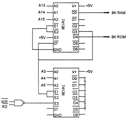
Figure 3.21 The LS74138 Decoder ...
54
Figure 3.22 More Efficient Use of the 74138 ... 55
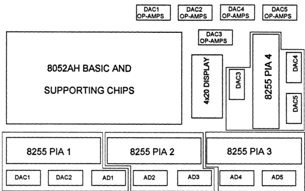
Figure 3.23 A Block Diagram of the PCB Board Designed .
...
56
Figure 3.3 The 4x20 LCD Display Address Map ... 58
Figure 3.4 A Block Diagram of the System with Hall Effect Sensors ... 63
Figure 3.5 The 555 Timer Used For a Clock Signal to the A/D's ... 64
Figure 3.51 The Wiring of the AD0804 Analog to Digital Converter ... 66
Figure 3.6 The DA0808 Digital to Analog Converter ... 68
Figure 3.61 The Output Signal Conditioning ...
68
Figure 3.7 The 8255 Control Word ...
...
70
Figure 3.8 The Resolution of the Theta Axis ... ... 72
Figure 3.9 The Silk Screen Layer of the PCB Board Designed ... 75
Figure 3.91 The Component Layer of the PCB Board Designed ... 76
Figure 3.92 The Solder Layer of the PCB Board Designed ... 77
Figure 3.10 TTL Equivalent of the Quadrature Decoding Program ... 86
Figure 4.1 The Circuitry for the High/Low Speed ... 88
Figure 4.2 The Ladder Logic for the Vertical and Twist Axes
...
90
Figure 4.3 The Ladder Logic for the In/Out, Theta, and Side/Side Axes ... 92
Figure 4.4 Limit Switch Logic for the Up/Down and Twist Axes ... 94
Figure 4.41 Limit Switch Logic for the Side to Side Axis
...
95
Figure 4.42 Expected Limit Switch Mounting on the In/Out and Theta Axes... 96
Figure 4.43 The Limit Switch Logic for the In/Out and Theta Axes ... 97
Figure 5.4 The EPROM Circuitry and Supporting Chips ...
100
Figure 5.41 The TTL Equivalent of EPROM 1 ...
109
Figure 5.42 The TTL Equivalent of EPROM 2 ...
110
Figure 5.43 The TTL Equivalent of EPROM 3 ...
111
Figure 6.1 Supplemental Wiring For the RG 300 UA Motor Control Card ... 115
LIST OF TABLES
Table 2.3 Sense Resistor Values for Non-Bodine Motors ... 23
Table 2.7 A Breakdown of the Motor Costs for this System ... 38
Table 2.71 A Breakdown of the Motor Driver Costs for this System ... 38
Table 3.2 The Controller Components and Their Place in Memory ... 53
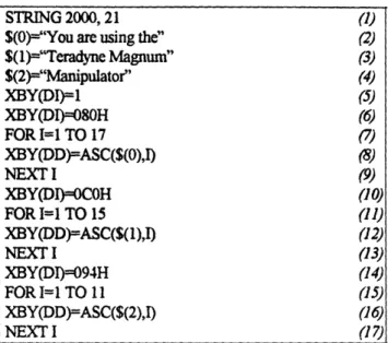
Table 3.3 A Sample LCD Display Program ...
59
Table 3.31 A Program to Use the Display and RAM Efficiently ... 61
Table 3.5 The 555 Timer Circuit Values ... 65
Table 3.51 The New 555 Timer Circuit Values ...
66
Table 3.9 Program to Check 8255's As Output Devices ... 80
Table 3.91 Program to Check 8255's As Input Devices ... 80
Table 3.92 Program to Check Optrex LCD Display ... 82
Table 3.93 Program to Automatically Range the Potentiometers ... 84
Table 3.10 Quadrature Decoding Program ...
87
Chapter 1: Introduction
Teradyne is a billion dollar company that makes their money in the business of electronics. Currently, they use a counterweighted mechanism to move their highly expensive and heavy testheads to the docking area where wafers are tested. This docking area can be at any variety of angles and orientations. This counterweighted version is/was old technology, and Alex d'Arbeloff as the insightful engineer entrepreneur that he is, looked around for a better solution. In the end, this problem was presented to the Precision Engineering Research Group at MIT under Alex Slocum.
Alex was to recruit a team of graduate students that would come up with a design that would match or beat the performance of the current manipulator design, while at the same time matching or beating the price of the current system. Alex and these graduate students were given roughly one year to come up with the design as well as two working prototypes. Since I had a background in controls and electronics, the control system for this manipulator was to be
my responsibility.
A mechanical manipulator with seven degree of freedom movement was developed with two versions of control systems: the first and simpler version was to provide power to the twist and up/down axis; the second would give a system with five motorized axis. The second system would still have motors on the twist and up/down axis, but would add motorization to the manipulator to give side/side movement, in/out movement, and theta movement. The theta movement was provided for by synchronous and opposite rotation of two motors/actuators on the cradle arms of the manipulator, and the linear, in/out movement was accomplished through the synchronous operation and same direction rotation of the same two cradle actuators. The
side/side movement was provide for by an actuator/motor located in the base of the manipulator. Shown below is an early version of the manipulator that was designed [18].
Li
Figure 1.1 The Magnum Manipulator
There were some basic factors that constantly dictated the direction of this design. The factors were cost, user friendliness (ergonomics), flexibility, control system packaging (space), and development time (June deadline). For this reason, there were three designs developed. The first was for the simple version providing power to only two axis, and this used a pendent control/pushbuttons to run some switching logic to the motors. The second was a take off from the first in that it used the pendent idea. This gave pendent control over the five axis, providing only two speeds of operation, hi and low, to the five motors. This design did not
allow for the 55 degree coordinated movement. The attraction of this design was the short development time and simplicity with regards to passing TUV inspection.
The third design was the most complex and flashy design (proposed by PERG student, David Levy). This provided a joystick that resembled the actual testhead manipulator. The joystick potentiometer signals would be taken to a microprocessor based controller that was designed specifically for this control application. Being a potentiometer, it was possible to provide variable motor speed. Coordinated motion could be provided for any angle of motion, included the desired 55 degree specification. An LCD display would provide the user with instructions and warnings about the use of the manipulator. Alarms would be sounded for warnings to the user about misuse of the manipulator. In addition to these features, it would be possible to program the EPROM through an RS 232 port, which would allow ease in updating the control algorithm for the system. The drawbacks to this system was the development time of the controller due to the bureaucracy present at Teradyne.
The evolution of this control system and the options considered is an interesting story in that it shows that a cost driven design will not always have a lot of finesse. In the beginning, there was talk of "automatic" docking, using proximity sensors and Delta Tau controllers to accomplish the dock. This moved to open loop control to avoid having to play by the rules that a fully robotic system would dictate, such as roping off the area and providing flashing lights and bells to warn the workers of the docking process. A lot of thought was given to produce a nice, ergonomic design for the above mentioned joystick that would "map" the movement of the joystick to the actual movement of the testhead. Also, an effort was made to
anticipate all of the problems that might be encountered in this area by the user, and an attempt to eliminate these problems was made through the ergonomics of the joystick.
Early on, without the controller specified, a microprocessor based controller was designed and breadboarded. It seemed to have the capability of satisfying the design criteria while maintaining a fairly reasonable manufacturing cost. This was then blocked since it looked as though it would take too long for it to be certified for use in a clean room where people are in close proximity to the robot, so an even simpler solution had to be found.
The next stage in the evolution of this system design was an extreme reaction to the blockage of the microprocessor idea. It was an attitude of basic rejection to any electronics solution that would require pcb boards, chips, etc., that might draw a large "time sink" in it's commissioning. It was thought that if this problem could be solved through straight switching and pushbutton logic, then this would be the solution that would most likely meet Teradyne's
approval.
This approach did not last a long time, though, when it was seen what would have to be given up in terms of manipulator functionality to obtain this easy solution. In fact, the easy solution was actually quite complex when researched, requiring sixteen, 4PDT pushbuttons. Even with these special pushbuttons, functionality was sacrificed since there were not enough poles in these pushbuttons to deal with new and improved logic requirements that had the inclusion of limit switches.
The next stage was a "stepping back" from extreme design, and was the use of EPROMs to be used as state selectors for the system. Truth tables were drawn up, some with up to 12 columns and 100 rows, to give the desired motor response at any given combination
of pushbutton and limit switch state. It required three EPROMs and various circuitry to protect the EPROMs, as well as some relay drivers to accomplish the control goal.
* Chapter 2 will introduce the hardware of the system, such as motors, amplifiers, relays,
limit switches, and basic motor controllers. The signal requirements of each will be discussed, as well as the cost found for each in per unit and quantity measurements.
· Chapter 3 will discuss the microprocessor circuitry that was designed specifically for
the manipulator control. The wiring of the circuit as well as the programming involved in this type of control will be investigated. The focus will be on the capabilities of this type of control.
* Chapter 4 will layout the pendent pushbutton logic that was attempted for manipulator
control.
* Chapter 5 will talk about the EPROM logic used for the manipulator control. The
basic wiring will be discussed, as well as the TTL equivalents of the information burned into the EPROMs for comparison.
* Chapter 6 will discuss the improvements that were made after the EPROM logic was
instilled.
* Chapter 7 will examine the whole project and present conclusions and
recommendations for fiuture control improvement.
Chapter 2: The System Hardware
2.1 The Joystick
The following is an illustration of the joystick that was developed to provide one solution to the control of the manipulator system. The focus of the design was to provide a "replication" of the actual testhead, which would make it easy to match joystick movement to the movement of the testhead. David Levy, a student in PERG, was the individual that provided most of the ergonomic advice, and this design is a result of his ideas.
Figure 2.1: The Joystick Designed to Operate the Five Manipulator Axes
The joystick was made to look like a testhead so that it would be possible to turn the joystick in the orientation of the testhead to easily map the joystick movement to testhead movement. The top of the joystick has an MSI model 510 spring return potentiometer. This potentiometer is mounted with a 5/8-24 threaded bushing. This was used to give the theta
MSI Model 510 Spring Return Pot
movement of the testhead. The potentiometer was 5 kf and gave 45 degrees of deflection, and when +5V and ground were applied to this potentiometer, a voltage signal indicative of the theta demand resulted. For zero theta actuation, a signal of roughly 2.5 V was produced. This
potentiometer was $83 for one unit, $44 in quantity.
To provide up/down, side to side, and twist motion, an MSI model 521Z three axis joystick was utilized. It gave and x-motion that corresponded to the side to side motion, a y direction motion corresponding to the up/down motion, and the end of the joystick had a potentiometer that was a converted model 510 to give the twist motion signal. The 55 degree docking requirement was taken care of in software by analyzing the up/down and side to side voltages, and proportioning the motor speed with this information. Each was a potentiometer that had +5 V and ground applied to it to produce a 0-5V voltage signal to represent each axis motion demand. This potentiometer was $188 for one and $93 in quantity.
A three position slide switch was used to give the linear in and out motion of the testhead. In the prototype, an inexpensive, Radio Shack version was used, but it would be desirable to replace this with a more robust, spring return potentiometer that could be used to give variable speed as opposed to the on/off control provided by the slide switch.
The safety trigger is from Electric Switches Incorporated (cat. no. U2-016, military no. M8805/111-001, otto P/N U2-016). It is .641" thick, 1.234" long, and .688" wide. The total travel is .440". The safety trigger was included so that the motors would not actuate unless this trigger was depressed. This safety trigger is the ergonomic equivalent of the pendant's enable pushbutton.
2.2 The Pendant
For some reason, there was a push for a pendent design to run the manipulator. On the MIT side in the beginning, this idea was not taken too seriously in that it was a totally un-ergonomic approach to the problem. However, there was some pressure exerted from a few different directions, and this idea was soon investigated. The first pendant proposal was made by Paul d'Entremont [17]and can be found on the following page. It is the most simple of the designs investigated, having two buttons to control each axis and then two enable buttons that would require two handed control.
With new control requirements, buttons were added to give compliance to the in/out and theta axis, the side to side axis, and the up/down axis. A pushbutton was include to release the swing brake, and a high speed button was added to give two speeds for the up/down and twist motors. This feature allowed high speed motor actuation when the testhead was a long distance from the dock, and a "creep" speed for fine tuning the testhead position when approaching the dock. Also, a latch release button was added to block control from the pendent and turn it over to Mike Chiu's linear planearization setup in a simple "hand shaking" process. It should be noted that the ergonomics of this pendent design would require of the user an Airline Transport pilot rating, a Commercial Driver's License, and have served as a Navy fighter pilot to have the coordination to use it correctly. Being a private pilot myself, a simple pilot's license does not seem to be enough training to run this pendent. On the page following the first pendent design, a second design for the pendent can be seen. This was a creation of Frank Parrish [8]. It should be noted that the pendant's used SPST momentary pushbuttons for all of the inputs except for the high speed pushbutton and the toggle
0%4
-C)
*
~~~~~~~~~~~~~~~~~~~C Lt)~~~~~~~~~~~~~~~~~~~~~~~~~~~~~~~~~~~~~~~~~~~~~~~~~~~~~~~~~~~~.sz C10,
I .
C~~~~~~~~~~~E
e
Q~
Ln 9L.~~~~~~~~~~~~~~ IC ,-i.0. N C4 ,r=. LU z>. '*
CZE
<
A
N
LU a C/) _ H-0
E
E
E E :6n-3
o
0
o
z
3
v1 CIL-vl In I. co PII s. em
;
PD co 04 .u vzcompliance switch. A DPDT pushbutton was used to switch between two combinations of fixed resistors to produced a voltage divider signal to the input of the UDC 800 analog control
card. The toggle compliance input was in fact a toggle, on/off button.
Although not ergonomically optimal, the pendent could be inexpensive and produced rapidly and reliably. This was the motivation to accept this solution for manipulator control.
2.3 Evolution of the Twist Axis
Depending on whether the manipulator was to be used on the east coast or west coast, there was to be 190 degrees of twist travel. It was desired to get this full rotational stroke within 30 seconds, so a rotational speed of 1 rpm was chosen as something to shoot for. Taking this back through some gearing (planet gear), this corresponded to a motor speed of about 5 rpm. The maximum torque load was to be 3400 lb-in at the planet gear, which corresponds to a motor torque of 340 lb-in. These torque values were found from cable force measurements performed in October.
From the above criteria, a Bodine gear motor was chosen (by Ryan Vallance). This motor delivers 300 lb-in and 13 rpm at this torque. At no load, it will rotate at about 17 rpm. However, this rotational speed is reduced when taken through a gear having a 10:1 ratio.
Initially, the model 856 controller was purchased from Bodine to run this motor. It took a plus or minus 10OV signal as an input and gave a proportional output speed. The problem with this controller was that it did not provide reversing to the motor. A +10OV signal gave the same speed and rotation direction as a -10 V signal. Also, the motor was seen to drift about one half a rotation after the control input was taken away. After consulting with Bodine engineers, it was decided that an optional "forward-brake reverse (FBR)" kit would have to be included. The price of the model 856 was $347 ($224 in quantity), and the FBR kit was to be an additional $105 ($71 in quantity). In addition to these problems, the controller was quite large (4.55"x7.27"x3.50").
A better solution to all of these problems was found in the form of an analog card and some relay logic. The UDC-800 was chosen, which takes a voltage signal generated from a potentiometer that comes with the package and gives a speed proportional to the pot voltage.
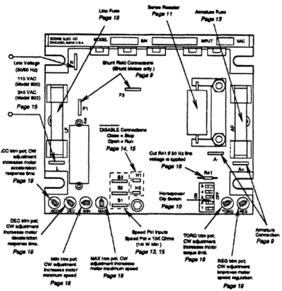
It runs off of 115 VAC, and produces an output voltage than ranges between 0 and 90 VDC, with the output current limited by the value of resistance chosen for the "Sense Resistor." The table shown below is a reproduction of the table found in the "Instructions for Installation and Operation" produced by Bodine. They show the Sense Resistance values for non-Bodine motors. It should be noted that for the 90V Bodine Motor that was used, a 0.1 ohm resistor was used, as specified by a Bodine representative.
Table 2.3: Sense Resistor Values for Non-Bodine Motors
Typical Current
Input Current
Output Current
Dip Switch
Sense Resistor
Limit DC Amps RMS (AC) DC Amps Settings Value (ohms)
Amps 0.29 0.16-0.31 0.10-0.19 5 0.1 0.52 0.28-0.54 0.17-0.34 4 0.1 0.88 0.50-0.90 0.31-0.56 3,5 0.1 1.40 0.70-1.50 0.43-0.93 2,5 0.1 2.20 1.25-2.25 0.78-1.40 2,3,4,5 0.1 3.40 2.00-3.50 1.25-2.18 1,3 0.1 4.20 2.754.50 1.68-2.78 1,2,3,4,5 0.1 8.20 3.75-6.25 2.30-3.90 2,4,5 0.015 10.4 4.75-7.75 3.00-4.80 2,3,4,5 0.015 15.0 6.50-11.00 4.00-6.80 1 0.015 16.4 7.50-12.75 4.60-8.00 1,3,4 0.015 20.0 8.50-15.00 5.30-9.30 1,2,3,4,5 0.015
The UDC 800 DC motor control board was selected to run the Bison up/down
motor and the Bodine twist motor. This card converts a small current, analog voltage to
a high current, high voltage ranging from zero to 130 volts, but this output voltage can actually be varied to suit the motor ratings. The speed is varied through three terminals: S1, S2 and S3. S3 is +12 volts, S1 is ground, and the analog input is varied on terminal S2. This variance at S2 can be accomplished through the use of a potentiometer used as a voltage divider, or an isolated voltage signal, such as one from a D/A converter with
amp isolation. For the microprocessor board designed, this signal was generated through
an 8 bit D/A converter and the isolation was accomplished through an op-amp in the differential configuration.
Lkw~~P Pum
u's
mclm
~P
trpot MAXdpe *pmfe W Pa e 1 RG pomt
CW ShA"_ MA
cw -"WW 1" cw
-hnme_, moor mlcrne mmd - m
nmmnm pid Page 1_ b men
Papr p 19
Figure 2.3: The Bodine UDC-800 DC Motor Control Card Above is a digitized reproduction of the UDC 800 card (Courtesy of Bodine).
There are two terminals on this board, H1 and H2, that when left open will allow
the motor to run on a signal input. However, when these terminals are shorted, the motor
will be disabled no matter what the input at S2.
There are some factory settings for this motor controller that should be noted.
The minimal speed pot is set for zero rpm, the maximum speed pot is set for 1750 rpm, the acceleration is set at approximately two seconds, and the deceleration is set at
approximately two seconds, also. The torque is set at 200% of rated load and is based on the dipswitch settings. The settings are controlled through the minimum and maximum
speed potentiometers, the torque or current limiting potentiometer, the
deceleration/acceleration potentiometers and also the regulation potentiometer which all
can be found in Figure 2.3.
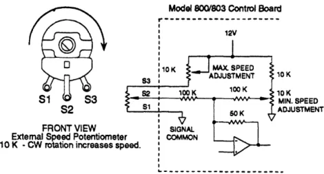
Modei 80a/803 Control Board
12V 10K 10K MIN. SPEED S2 FRONT VIEW External Speed Potentiomete 10 K - CW rotation increases sp
ADJUSTMENT
Figure 2.31: The UDC-800 Speed Control Terminals
The analog input S2 and the ground on S1, as mentioned before, needs isolation.
The input should be conditioned to range between zero and ten volts DC. The motor
disable terminals, which are terminals H1 and H2, need to be optically isolated. If these
considerations are not taken, damage to the microprocessor board could occur.
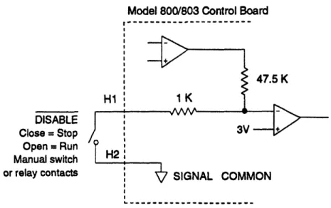
Model 800/803 Control Board
I---.5 K DISABLE Close = Stop Open - Run Manual switch or relay contactsFigure 2.32: The UDC-800 Card Disable Terminals
To set the minimum speed , the minimum speed potentiometer needs to be turned
fully counter clockwise, with this setting a starting point to adjust from. This minimum
speed adjustment will account for between 0-30% of rated speed, which means that fully
counter clockwise would correspond to 0 RPM, and fully clockwise would be 30% of the
rated speed. For the maximum speed adjustment, the maximum speed potentiometer, when it is fully counter clockwise, will correspond to 60% of the rated speed, and will correspond to 100% of rated speed when fully clockwise.
The torque adjustment can also be found on this card. Since torque is proportional to current, this can also be seen as a current limiting adjustment. The torque trim
potentiometer has been set at the factory so that the motor will never see more than 200%
to 250% of its rated current input (according to Bodine). This adjustment should be set in
accordance with load requirements.
The acceleration adjustment can be made by turning the acceleration trim
acceleration time, with 0.2 seconds being the minimum time to accelerate the motor to full
speed. The maximum acceleration time is 10 seconds, and can be achieved by turning this pot clockwise. The deceleration adjustment is exactly the same as acceleration
adjustment, except that this is the time that it takes to go from full speed to 0 speed when
an input is taken away. These values also range between 0.2 seconds and 10 seconds, respectively.
The most critical adjustment on this card is the regulation adjustment. This
regulation trim potentiometer is used to regulate speed under changing loads, and if you
have a constant load, it does not need to be changed. However, in our case, we are going to have constantly changing loads and this has to be adjusted to account for it.
The steps for this adjustment are as follows:
(1) Determine the minimum and maximum positions of the trim potentiometer and
adjust them to 75% of the full clockwise rotation.
(2) Operate the motor at approximately 33% of the full speed and record the speed
at no load.
(3) Reconnect the load and operate the motor again, adjusting the pot until the
motor reaches the unloaded speed recorded in step 2.
(4) Disconnect the load and operate the motor without adjusting the speed control
and measure the unloaded speed. If it is the same as the value recorded in step 2, no further adjustments are required. The control is now calibrated
for minimum speed changes under varying load conditions.
(5) If, however, the unload speed has shifted, repeat the procedure until more accurate regulation is achieved [2].
There were problems that were noticed with the alpha version of the manipulator
when it was powered the first time. The gears that connected the motor to the ball screw
were not meshing perfectly, which gave a changing load. This gave a varying voltage out
to the motor to try and compensate for the changing load (the torque changed, so the
voltage changed, also). After the regulation adjustment was made, these problems
disappeared, and the motor performed at a fairly constant speed through the full up/down
stroke of the Bison motor and the twist of the Bodine motor. These problems developed
on the day of the alpha electrical presentation to Teradyne representatives and was slightly
unsettling.
One troubling specification set by Bodine is the normal operating conditions,
which calls for a duty cycle of 8 hours per day, 5 days per week without frequent reversals
and starts or stops. This could prove to be a little inadequate, depending on how had the manipulator shall be used.
The dimensions of the UDC 800 control board are 4.4 cm wide x 3.7 cm deep x
1.3 cm long and the net weight is one pound. The control speed range is up to 50/1 ratio
and this motor controller can handle up to a 3/4 horse motor. It requires 115 volts AC
and can run at 50 or 60 hertz, but if it is run at 50 hertz, the R41 resister needs to be cut.
There may be problems in the future confusing the board that will be used for twist motor
with the one used for the up down motion because the up/down motor (Bison) is limited
to 90 volts DC while the Bodine gear motor can be ran at 130 volts DC and actually needs to be ran at this value to obtain the speed that we will require of it, which is 1 RPM of test head twist. They both require different sense resistors. The Bodine requires a .01 ohm sense resistor while the Bison requires a .015 ohm sense resistor. In critiquing their
design, the logic that they use to disable the motor seems exactly backwards. They
actually short terminals Hi to H2 to disable it, which is not fail safe. If you remove the
wire from Hi to H2, the motor can run, and for this reason, we need to actually "hot
switch" the power from the UDC 800 with a relay. If this was not the way it was set up
and you had to short HI to H2 to run it, we could actually switch the AC power input to it and go to a much smaller relay.
Limit switches were used to limit the motion of stroke to the 190 degrees of rotation specified by Teradyne. Since this was a gearmotor and not back driveable, no brakes were required to keep this motor from rotating during a loss of power.
2.4 Evolution of the UP/Down Axis
There were many different ideas tried before the final selection was made for the actuators, amplifiers, motors, and controller interfaces to be used in the final Teradyne Magnum Manipulator. In the beginning, the up/down axis was to be run with a PMI motor.
Several of the motors from this distributor were checked for torque, speed range, packaging, price, and other basic criteria, and were found to fall very short. The representative was also fairly difficult to deal with, and was very reluctant to give pricing for two hundred fifty units a year.
The next idea that was checked was using a Milwaukee drill motor to run the up/down lead screw. The drill would have to be torn apart and some sort of mounting developed for it, but the main drawback of this idea was the noise generated by the drill motor. It was rejected for this very reason.
The last and final up/down axis driver tried was the Bison 300 VDC motor [12]. This worked fairly well for the price, matched the torque and speed requirements of the system, so this was chosen to run the up/down actuator.
The UDC-800 motor controller board was also used to run this motor. The only
difference between the two setups were the sense resistors used; the Bison called for a .01592 resistor. Also, the min and max speed would be varied by the manipulator assembler.
Two form CC relays [14] were used to switch the power from the UDC-800 card to the motor, as well as reversing the polarity to give reverse motor direction. Dynamic braking was accomplished by tying a 25 , 25 W resistor between the motor power lines when power was removed from the motor.
An Inertial Dynamics brake was used on the Bison motor that would be engaged unless 24 VDC was applied to it. This was fail safe in that if there was a power failure, the up/down axis would be locked. This brake required .369 A at 24 VDC. A mistake was made in the beginning in that a 90 V brake was used, and the motor leads and brake leads were tied in parallel. The problem with this setup was that the motor would only see 90V at the top speed range, so the brake was always engaged unless operated at high speed. The "staying" voltage required to keep the brake disengaged was much less than 90V, but this was irrelevant since it was not desired to run the motor at full speed before running it at a lower speed.
Compliance in this axis was to be provided by a "cushion of air," first by an air piston and finally by some Firestone Airstroke Cylinders. Compliance brakes were added to "lock out" this compliance when not desired, such as when the manipulator was kinematically coupled to the handler. Two, 24 VDC Warner brakes were used for this purpose, each requiring .733 amps to disengage. As pointed out in a meeting, this compliance could be eaten up by external influences, such as a cable bundle riding on the testhead, so limit switches were added to alert the system of this occurrence. Limit switches were also used to limit the stroke of the up/down motion so that the Bison motor would not be run after reaching a mechanical stop.
Due to a load that would drive the motor, turning the motor into a generator, the Bodine UDC 800 card was replaced with a Minarik RG 300 UA Regenerative Control card. This card could provide a reverse bias to slow the load as the testhead was lowered. This removed the Potter and Brumfield relays from the design, replacing them with small SPDT, solid state pc relays. This will be discussed more in the "Improvements" chapter of this thesis.
2.5 Evolution of the In/Out and Theta Axis (s)
At first, drill motors were investigated as a possible driver of these two axis. However, due to the noise produced by these motors, this idea was quickly rejected.
Thompson actuators were then selected to run these two axis. Western servo
amplifiers were used to take a plus or minus 10 VDC control signal and convert it to a higher voltage/current signal to run the Thompson motor/actuator combination. The problem found with this idea is the need for position feedback on the Thompson actuator in the form of Hall Effect Sensors. These produced a current sinking pulse which could be signal conditioned to produce a TTL logic high every .033 inches. Another problem found was that the shaft of the Thompson actuator would start to rotate at the end of the stroke.
Western Servo had two types of amplifiers that could be used. A "linear" amplifier could be used, but was more expensive than the "pulse width modulation" amplifier they supplied. The problem with this type of amplifier was that it had problems with high frequency noise, which was evident the first time the actuators were run. The actuators would actually vibrate from the constantly changing amplifier signal to the motor due to this noise.
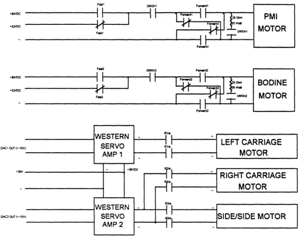
OF9off/ F.,-dl Fest OO11O Fcn1 Fy~~~~~d1vn .80VDC *32VDC .80VoC *32VDC PMI MOTOR WESTERN RI
oES:ER
WESTERN7
'"l -gLEFT CARRIAGEDAC1O af (*-IOV) SERVO
AMP 1 --- MOTOR
RIGHT CARRIAGE MOTOR
AMP2
Figure 2.5: An Early Block Diagram of the System Switching
To get more accurate theta movement, a stepper motor system was selected. A stepper motor was to be placed in each carriage arm, and to get linear in/out movement, the steppers would rotate in the same direction and speed. To get theta movement, they would be run at the same speed but in opposite directions. This setup would give highly precise
movement that could keep the center of the testhead constant. The steppers at "half step" settings would give .9 degrees of shaft rotation per stepper pulse.
The 23D204 stepper motor from Anaheim Automation was chosen for the carriage motors. This is a four phase stepper, with options of full and half stepping. It boasts a "fast damping" feature for better control, low noise, and high torque to package size ratio. The specification sheet on this motor calls for 1.8 A/phase. The motor has a 1/4" shaft diameter,
and requires 100 oz-in. of holding torque. This is the torque that is required to make the motor backdrive. Although backdriving in most motors can be seen as a form of compliance, in stepper motors this is not true compliance, since there is no springiness to the motion, and once the motor steps to a new rotation angle, it stays there.
The TM3000 trackmount driver [11] was selected as the amplifier to run this stepper motor. This motor requires 12-28 VAC or 10-40 VDC for a power input. The inputs are TTL and CMOS compatible. The excitation choices are dual phase, full step operation as well as half step operation. The full step operation is brought on by energizing only two of the phases at a time, while half step operation will be seen when all four phases are energized. The half step mode seemed to provide better performance in that it was possible to run the motors slower with less vibration.
Some of the most important inputs to this amplifier are the on/off, direction control, clock, and mode select inputs. There is also a +5VDC output on the amplifier that could be used to run some logic circuitry, but it is limited to 100 mA. For this amplifier, a logic "0" is defined to be between 0 and .8V, and a logic "1" signal is defined as 3.5 V-5.0 VDC.
A logic 1 to the direction control bit (bit 3 of terminal block 2) makes the motor turn clockwise, while a logic 0 makes the motor turn in a counter-clockwise direction. The motor is on when a logic is seen at bit 5 of terminal block 2. A logic 1 at bit 4 of TB2 gives half step operation, while a logic 0 gives full step operation. The problem with this amplifier is that bit 5 of TB2, the on/off control bit, is pulled high with a 10 kQ resistor. This means that if the wire running to this bit is severed, the motors run. This may cause problems with TUV inspections, and Anaheim may be approached to place a pulldown resistor on this bit in their custom engineered package for the later versions of the manipulator.
The speed of the motor was varied by changing the frequency of the oscillator signal taken to the amplifier. The oscillator that was used was the AA2076 from Anaheim
Automation. This element was powered with 9-12 VAC. There were two speed ranges, low and high, giving a square wave signal that varied 40 Hz-2kHz and 450 Hz-24 kHz,
respectively.
The run input on the oscillator was a logic "0", and the stop input was a logic "1." Since this bit had a 4.7 kfl pullup resistor, this was a good setup; if the wire came loose, the bit would be pulled high, turning the oscillator off.
The amplifier's 12-28VAC power supply requirement and the oscillator's 9-12 VAC power requirement was taken care of with a 200W transformer with three taps on it; between the middle tap and either of the other two taps was a voltage of 12.6 VAC, and between the outer two taps, a voltage of 25.2 VAC was produced. This transformer was also purchased from Anaheim Automation.
Compliance in this axis was to be given by disengaging the Lenze stepper brakes and just "back driving" the stepper motors. However, when the alpha was up and running, it was seen that no brakes were needed in that it was impossible to back drive the stepper motors. This provided a control problem since it was impossible to provide compliance in this axis with this setup. For this reason, the stepper brakes were discarded, a single ended stepper motor instead of a double ended stepper motor was selected, and an electric clutch was used to provide compliance. The clutch was to be engaged always unless a manual compliance button on the pendent was pressed, in which the clutch would disengage and compliance in these axis would be present.
2.6 Evolution of the Side/Side Axis
The same ideas tried on the In/Out and Theta axis were tried on this axis. Stepper motors were also selected to drive this axis, and the compliance issue was treated in the same manner.
A schematic of this total system can be seen on the following page. This includes information on the hookup of the Anaheim stepper motors and amplifiers and the UDC 800 Motor controller cards.
, & I U , I I - I ' &. 1 , 1 > a U a 4 ID OO
zo
-I
Uzo +-um"I-Jo
wurn H JHnoi
13 1I Doz
>-ZO wum OCI - J -cm." I I 6 ., V j * E 1 N-e I 2 E O 0u C ( c a c C 0 QC '.a
0
I. o etc
1 vC Jc %Pa,
o o I cc 4 a~a W 3 _ _mt _h -h __ >a §m Z maz cZE0J
z i- 0naIF I I z ULLZH L JCZIZJLUi\ a
I- z0w <CCCzf-i Q. r c " D . 1 11I . U < O nI P,2.7 Cost Breakdown
Table 2.7: A Breakdown of the Motor Costs for this System
Axis Motor Model # or Voltage Current Cost per Cost per Misc. Manu. Descriptio (VDC) (A) one ($) 250 ($) Costs ($)
n
Twist Bodine 42A-GB 90V 1.8 A 378.45 277.06
PM DC Gearmotor (300 lb-in) Up/Down Bison 300 DC, 90V 2.76 A 250 1/4 hp, 106 in-lb
Side/Side Anaheim TBD3XXX 10-40V 2A/phase 581/3 513/3
X nominal
Left Anaheim TBD3XXX 10-40V 2A/phase 581/3 513/3
Carriage X nominal
Right Anaheim TBD3XXX 10-40V 2A/phase 581/3 513/3
Carriage X nominal
Table 2.71: A Breakdown of the Motor Driver Costs for this System
Axis Driver Model # Cost per one ($) Cost per 250 ($) Misc. Costs ($) Manu.
Twist Bodine UDC-800 80 60
Up/Down Bodine UDC-800 80 60
Side/Side Anaheim Included above Included above Included above Included above
Left Carriage Anaheim Included above Included above Included above Included above Right Carriage Anaheim Included above Included above Included above Included above
It should be noted that there is a one time engineering fee of $4500 for designing the simpler system to run the stepper motors.
2.8 Some Early Design Switching Issues:
The following were the control options for the Teradyne Magnum Manipulator
when Western Servo amplifiers were to be used:
1. Two Western Servo amplifiers with a 2 amp chassis/power supply.
2. Two Western Servo amplifiers with a 2 amp chassis/power supply and a Bodine amplifier/power supply/analog interface/forward brake reverse (FBR).
3. Four Western Servo amplifiers with a 4 amp chassis and a Bodine amplifier/power supply/analog interface/forward brake reverse (FBR).
4. Five Western Servo amplifiers with a 6 amp chassis/power supply. Choice 1:
If two Western Servo amplifiers were used to control the 5 motors, then there
would be a need to use relays to switch the amplifier's output to the motors, depending on
the joystick state. This would limit the movement of the manipulator to only 2 axis
movement at any given time. This would work, since only the linear in and out motors on
the carriage and the up/down and side/side motors (for the 55 degree dock) need to be run
at the same time. In software, the movements could be given a precedence by having whichever joystick demand came in first to be the one that is acknowledged. However,
this is only a possibility if we can replace the 90V Bodine motor used for the twist axis
with a 36 V equivalent. Position feedback could be obtained for all five axis's with only
the two internal 8052 counters.
Choice 2
This is the same option as choice one, except that the 90V Bodine motor is not
replaced with a 36 V motor. Choice 3
This option has four amplifiers from Western Servo (and it's accompanying 4 axis chassis/power supply) and the 90 V Bodine motor amplifier and power supply. This
option uses no relays to switch between the controlled axis, so it does not have the
limitation of only 2 or 3 axis control. Since no relays are used, no I/O lines are needed from the controller. There is still only position feedback on two axis's, which will now be
dedicated to the in and out motors, since there could be the possibility of them binding up.
This eliminates the worry that the software will switch one relay closed before opening the
previous closed one, and having two different signals "fight each other."
Choice 4
This is the same as choice 3, except that the Bodine motor is eliminated for a 36 volt equivalent, and a 6 axis chassis power supply will now be used.
These were some of the factors in the decision making process. It was not
desirable to have any switching, but since the design was very cost driven, it was necessary. In the end, it was decided to switch between two Western Servo amplifiers
running three Thompson actuators, and have separate cards to run the Bison and Bodine
motors. However, these complicated issues disappeared when the decision was made to
There was some talk of using one UDC 800 card, and switching the output to the
Bison and Bodine motors, but since the card was so inexpensive, it was decided to have
one for each motor.
The biggest consideration when deciding to use any relays for switching was the
presence of the TUV influence. Each additional element in the electrical design would be
one more element for TUV to molecularly disassemble. For this reason, the design that
produced the least amount of switching was the most desirable.
2.9
Limit Switches
Twelve limit switches were used in the system to give limitations to the stroke of
the up/down, twist, in/out, theta, and side/side motions as well as an up/down compliance. The V3-101-D8 miniature limit switch from Micro Switch was selected to serve this
purpose. The normally closed contacts on these limit switches were used so if the lines to
the limit switch were broken, it would give an indication of a "made" switch. This made them more fail safe for TUV.
2.10 Pressure Switch
The PSW-523 [13] pressure switch from Omega was selected to give an indication of the pressure in the air cylinder. This pressure switch could be mounted in systems seeing up to 100 psi, and the pressure at which this device switched could be varied between 3.0 psi and 96.5 psi. The deadband for this unit is 1.5 psi to 3.5 psi, depending
on the switching pressure. The normally closed contacts off of this unit were also used for
the same reason mentioned in the limit switch section. Logic was provided to disallow
up/down movement and engage the up/down brake if the air cylinder pressure was not
present in the system, which was indicated by this pressure switch.
2.11 Swing Brake Solenoid
This solenoid had quite a history in the development. In the beginning, a solenoid
was selected that required upward of 80V for a few milliseconds to get the solenoid to
disengage the swing brake, and about 28V to maintain the disengagement. Some thought
was given to amplifier logic that could accomplish this, as well as switching power to it with relays. One design was developed that would actually apply 90 V to the solenoid, and when the rod of the solenoid was pulled back in the solenoid case, a lever would
actuate throwing a resistor in series with the solenoid. This gave a resistor/solenoid
combination that acted as a voltage divider, and the appropriate resistor size could be
selected to give a voltage drop of 28 V across the solenoid.
These considerations were made so that a smaller solenoid could be used and it
would be easier for the mechanical designers to package it. However, this design was
complicated and required a 9OVDC power supply to run it, and since it was an expensive electrical solution to a mechanical packaging problem, was quickly discarded.
The Warner ERS 49 brake was selected for this axis. It is a failsafe brake that
Chapter 3: The Microprocessor Design
There are many components to the basic 8052 circuit [1,3] that was developed to control the magnum manipulator for Teradyne. They can be broken into several categories,
such as:
I. The Intel 8052AH Microprocessor (with onboard compiler) and microprocessor support chips
a. Port 1
b. The Data lines, Address lines, and the 74573 Tri-State Octal D-type Latch (Address Latch)
c. The internal counters (TO and T 1) d. Reset
e. Serial input and output and the Max 232 serial interface chip (Only included in the prototype version)
f. Read and write
g. XTAL1 and XTAL 2 and the 11.0592 Mhz clock h. The interrupt lines
i. Pulse width modulation
II. Memory
a. 8Kx8K Static RAM
b. 74138 Decoder (one of eight) and memory mapping c. 27128 EPROM
d. EPROM programmer (only included in the prototype version)
mI.
The display and display support chips a. Optrex 4x20 LCD display b. 7400 NAND Gate chipIV. The signal conditioning to the counter pins on the microprocessor
V. The A/D converters used to bring the joystick signals into the Basic 52 program a. The reference voltage signal
b. The clock signal (555 timer)
VI. The D/A converters and the output signal conditioning used to take the controller action to the motor amplifiers.
a. The reference voltage signal
VII. The 8255 PIA's that were used to send out and bring in the information to the D/A's and from the A/D's, respectively.
All of the above information can be found in this chapter. Hopefully, by listing it in a logical order, the understanding of the topics discussed will come easier.
CL Cet E 5= '0
(-6
to ._ o .)3.1 Microprocessor and Microprocessor Support Chips:
With the control of the manipulator still up in the air, microprocessor circuitry was investigated that could accomplish this task. In particular, the Intel 8052 and supporting chips was selected. This chip can be considered an "embedded controller" in that it acts as a mini computer and can be reprogrammed to suit the control need. This option has several
advantages over using a pc or some commercially available controller to run the manipulator. These include lower cost, smaller packaging, less power consumption and stand alone capabilities. The main drawback to this option is that it intimidates the marketing personnel trying to sell this to the public.
Embedded control [4] will usually fall into one of three categories: Sequential control, closed loop control, and data control. Sequential control can be found in most machine tooling processes. An example of this would be a high speed drilling operation in which parts on a conveyor belt are brought to a drill until a limit is made that indicates proper positioning. The conveyor is turned off and the drill is turned on. Next, the drill is lowered to a certain depth over a given amount of time to drill the part. Finally, the drill is retracted, the limit is reset, and the conveyor is restarted.
Data control would be for the application of state control in which a lot of I/O work is needed. An example of this would be the monitoring of limit switches and pushbutton states, and then making decisions on the desired output (sound familiar).
Closed loop control would involve classical control techniques such as P+I+D control. A process variable would be monitored, and depending on the setpoint, a calculated corrective action would be sent out to a final control element to change the process variable and bring the
error to zero. The control algorithm would be digital in nature with the resolution depending on the number of bits that are used to bring in the information to the controller.
There are several microprocessors in the Intel family similar to the one that was used for this design. The 8052AH with onboard Basic was used, but several could have taken it's place. The 8051, for example, has:
* 8-bit CPU optimized for control applications
* Extensive Boolean processing (single bit logic) capabilities * 32 bi-directional and individually addressable I/O lines * 128 bytes of on-chip Data RAM
* Two 16 bit timers/counters * Full duplex UART
* 5 source interrupt structure with two priority levels * On chip clock oscillator
* 4K bytes of on-chip Program Memory * 64 K Program memory address space * 64 K Data memory address space
The 8052 AH Basic has the additional improvements over the 8051: * 256 bytes of on-chip Data RAM
* Three 16 bit timers/counters * 6 source interrupt structure
* 8K bytes of on-chip Program Memory
Microprocessors have sometimes had a bad reputation follow them around, and this could be due partly to a lack of understanding. The following sections will go through and try to increase the readers understanding of the circuitry used to control the manipulator as well as the programming capabilities. Hopefully, this may dispel some of the worries that marketing had about the use of a microprocessor to control the manipulator.
Port 1 on the 8052 are the first eight pins on the 8052AH (P1.0-P1.7). Some of the pins may be used as input/output bits, and were found through experimentation to be bits 0-2,
4, and 6-7. This corresponds to pins 1-3, 5, and 7-8, respectively. There are internal pullup resistors on the bits of port which make them float high, so a ground true must be used for input. Bit manipulation can be accomplished with logical AND and OR statements in the Basic-52 language.
Pin 4 of port 1 is the address latch enable (NOT). This is ANDed with pin 30, which is the ALE (address latch enable) pin, to produce a signal to the 74573 to control the
multiplexing of the address and data lines. Since the 8052 only has an 8 bit data bus, but has 16 address lines, the lower 8 bits of the address are shipped out on the data bus and latched by the 74573, and then the actual data is shipped out on the data lines. This latching is enabled by this ANDed combination. The upper eight address bits are shipped out on lines A8-A15, as
expected. The 573 was used over 373, since the 573 provides a straight shot through to the other side, input to output, which makes the circuit board design a little simpler. It should be noted that the 8052 automatically takes care of this latching and was not part of the controller program.
In the beginning, Thompson PPA actuators were to be used for the in/out, theta, and side/side motions. These motors could vary as much as 15 %, so there was a need for position feedback to keep the motors turning at the same rate to maintain pure, linear motion. Hall effect sensors were to be used. These produced a pulse signal every 0.033 inches of actuator
extension, and this pulse from the hall effect sensor on the left and right carriage motors was taken to TO and T1, respectively. TO and T1 (pins 14 and 15) are internal, 16 bit
counters/timers to the 8052. The counters were turned on by manipulating the TMOD register with a logic statement. It should be noted that these counters can handle up to a frequency that is 1/24 of the clock frequency (11.0592 MHz).
The terminals 12 and 13 are the interrupt bits of this microprocessor. These bits can be connected to logic that will generate a low to interrupt the routine that is running in RAM. The "ONEXO" and "ONEX 1" statements can be included at the beginning of each program to give the microprocessor a set of instructions to follow upon an interrupt being sensed. Usually, this statement can point to a subroutine that will only be encountered on the generation of an interrupt.
These interrupts could be used to replace the pendant with a hex key pad. A hex key pad is nothing more than what is found in most office telephones, and can be purchased separately from a telephone. This pad has sixteen keys, and the 74922 chip can be used to interface this module. Only four address lines and a chip select line are required. The interrupt line senses when a key is pressed, and the external byte statement can be used to pull off the lower four bits of the data which correspond to a specific key hit. Then, a specific subroutine can be assigned to be run on a specific key hit.
A nice feature of using this over the pendant is that the hex key pad is extremely light weight, not to mention that a template can be easily layed over the top of the keys if there is a need to change the function of the keys or relative locations.
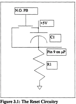
A momentary, normally open pushbutton was used, along with a 4.7 uF capacitor and a 1 kfQ resistor, as a RESET to the 8052 (pin 9). When the button is pressed, the capacitor is shorted and pin 9 sees a high. When it is not pressed, the capacitor charges, producing a low to pin 9. This means that this is a RESET high situation.
Figure 3.1: The Reset Circuitry
The RESET was included for situations where the program locked up for unforeseen reasons; the same thing could be accomplished by just turning the total unit off. This reset was included only in the breadboard version since each jumper wire acted as an antenna that could
"crosstalk" with one another.
In the prototyping process, a means of communicating with the 8052 was needed. The MAXIM 232 serial interface chip was chosen for this. It provides dual, serial port data
transfer, and the serial send and receive signals from an RS 232 connector were taken to the inputs of this chip. The output send and receive signals from this chip were taken to the serial in and out bits of the 8052 (pins 10 and 11, respectively). The function of this chip is to convert the 12V signal generated by a serial port to a 0-5 V signal readable by the 8052. There were
four, .1 uF capacitors used with this chip, which went along with the specification sheets.
Other size capacitors were tried and worked, but a large deviation from this value caused problems when downloading programs from the PC into RAM.
The clock that was used had a frequency of 11.0592 MHz. This signal was taken to XTAL2 (pin 18) on the 8052, with XTAL1 (pin 19) taken to ground. This setup is not valid for the "Micro-mint" version of the 8052.
A special bit that is contained within the port 1 bits is the PWM bit (P1.2, pin 3). "Pulse Width Modulation" statements can be used to generate a square wave signal at a given frequency and duty cycle. This can be used to drive a speaker that could sound an alarm or produce a "beep" after each key stroke of a hex key pad (if used). It should be noted that the frequency and duty cycle of these pulses can be varied very easily within a program to meet a specific tone requirement. This bit can still be used for input and output applications.
The format for the pulse width modulation statement is:
PWM A,B,C
where A is the on time of the pulse in clock cycles, B is the off time of the pulse in clock cycles, and C is the total length of the pulse.