HAL Id: hal-00472658
https://hal-polytechnique.archives-ouvertes.fr/hal-00472658
Submitted on 12 Apr 2010
HAL is a multi-disciplinary open access
archive for the deposit and dissemination of
sci-entific research documents, whether they are
pub-lished or not. The documents may come from
teaching and research institutions in France or
abroad, or from public or private research centers.
L’archive ouverte pluridisciplinaire HAL, est
destinée au dépôt et à la diffusion de documents
scientifiques de niveau recherche, publiés ou non,
émanant des établissements d’enseignement et de
recherche français ou étrangers, des laboratoires
publics ou privés.
Radiofrequency conical emission from femtosecond
filaments in air
Benjamin Forestier, Aurélien Houard, Magali Durand, Yves-Bernard André,
Bernard Prade, Jean-Yves Dauvignac, Franck Perret, Christian Pichot, Michel
Pellet, André Mysyrowicz
To cite this version:
Benjamin Forestier, Aurélien Houard, Magali Durand, Yves-Bernard André, Bernard Prade, et al..
Radiofrequency conical emission from femtosecond filaments in air. Applied Physics Letters, American
Institute of Physics, 2010, 96 (14), pp.141111. �10.1063/1.3378266�. �hal-00472658�
Radiofrequency conical emission from femtosecond filaments in air
B. Forestier1, A. Houard1, M. Durand1, Y.B. André1, B. Prade1, J.-Y. Dauvignac2, F.Perret2, Ch. Pichot2, M. Pellet3 and A. Mysyrowicz1,a)
1
Laboratoire d’Optique Appliquée, ENSTA ParisTech, Ecole Polytechnique, CNRS UMR 7639, 91761 Palaiseau, France
2
Laboratoire d'Electronique, Antennes et Télécommunications, Université Nice-Sophia Antipolis, CNRS UMR 6071, 250 rue Albert Einstein, 06560 Valbonne, France
3
Ministère de la Défense, F-00457 Armées, France
We show that the broadband conical emission associated with filaments in air extends down to the radiofrequency region. This RF emission which originates from the longitudinal oscillation of charged ions formed during filamentation is strongly enhanced by the presence of a longitudinal static electric field.
Femtosecond filamentation, a process during which an intense subpicosecond laser pulse launched in atmosphere self organizes in the form of a collimated beam is the subject of active investigations (for a recent review see ref 1). Filaments consist of a hard core where the self-focused pulse intensity is sufficient to ionize air molecules, surrounded by a laser energy reservoir contributing to the stability of the core. Filaments are thus able to convey high intensities over long distances, well beyond the limit imposed by diffraction, leaving in their wake a short-lived plasma column. A signature of filaments is the appearance of a forward oriented conical emission extending over a large frequency domain, from the UV to the THz1-7. While the origin of the visible part of the conical emission is still a question of debate (X waves, Cerenkov emission1-4), the low frequency THz component is now well understood5,7. It corresponds to a Cerenkov-like emission from free electrons oscillating longitudinally in the plasma column. This THz emission is strongly enhanced by the presence of an external static electric field8-9 and some evidences of RF emission from a biased filament have been reported 10.
In this letter, we investigate experimentally the conical emission of filaments, in the RF range (MHz to GHz) when an external static electric field oriented along the filament axis is applied. We detect a broadband emission between kHz and GHz and show that this emission is in fact the analog of the THz Cerenkov emission reported earlier, except that here the motion of electrons is replaced by the motion of charged molecules.
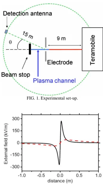
The experimental set up is shown in Fig. 1. The measurements were performed outdoor, in a free environment, to avoid unwanted reflections. The laser used for this experiment was the TERAMOBILE11, a CPA laser chain based on Ti:Sa technology. It delivers pulses with a peak power of several TW at 800 nm (pulse energy: 150 mJ; pulse duration of 50 fs; repetition rate 10 Hz).Since its peak power is far above the critical power for the onset of filamentation (3 GW in air for a wavelength of 800 nm), a bundle of ~ 20 parallel filaments were formed after a few meters of propagation. In order to regroup the plasma columns from the individual filaments into a single column, the laser beam was weakly focused with a 10 m focal length telescope. A plasma column of ~ 7 mm diameter was then obtained, starting 1 m before the geometric focus and extended over at least 2 m10. In order to apply a longitudinal electric field to the plasma column, a circular electrode with a central hole was placed at the beginning of the plasma channel (See Fig. 1). A high voltage (up to 50 kV) was applied on the electrode. The end of the plasma column was precisely fixed by inserting a thick dielectric block in the beam path 20 and 50 cm after the electrode. Two types of electrodes have been tested: the first had an inner hole diameter
d of 2 cm and an outer diameter D of 10 cm, while the second electrode had the dimensions d = 2 cm, D = 100 cm. The
corresponding calculated electric fields on the propagation axis are shown in Fig. 2.
Detection of the RF emission was performed with two planar integrated antennas: antenna A has an optimal response in the range 150 MHz-2 GHz, and antenna B from 1 to 6 GHz12. The transfer function in reception of antenna A was measured with a network analyzer in the spectral range 100 MHz - 5 GHz showing a quasi flat response over this spectral range (see Fig. 3). Some measurements at still lower frequencies were performed with a magnetic loop antenna (bandwidth: 9 kHz to 30 MHz). The reception antennas were set at a distance of 15 meters from the filament and could be displaced on a quarter circle centered around the electrode (see Fig. 1). The antennas were set to detect the electric field component (perpendicular to the acquisition circle radius) in the horizontal plane defined by the filament and the detection point. The RF signal from the reception antennas was directly digitized with a real time oscilloscope (Tektronix DSA700000, 6 GHz bandwidth). Measurements were performed as a function of applied field, angle with respect to the filament axis and plasma column length. For each measurement point, the background noise level was also recorded with the laser operating but stopped before filamentation.
A typical electric signal is shown in the inset of Fig. 3. It was recorded at angle 90°, perpendicular to the filament axis, with electrode A and an applied voltage of 40 kV. The corresponding spectrum obtained by Fourier transformation is shown in the same figure. As can be seen, a broad emission, extending over the entire antenna bandwidth is observed.
a
Author to whom correspondence should be addressed. Electronic mail: andre.mysyrowicz@ensta.fr.
Measurements with the magnetic loop antenna confirmed that its low frequency tail extends to the kHz domain. Fig. 4
shows the dependence of the spectral amplitude at 140 MHz as a function of applied voltage. For this measurement, a second grounded electrode was set at a distance of 14 cm from the other electrode. Below 5 kV (corresponding to a maximum external field of 330 V/cm in a single electrode configuration), the signal is buried in the ambient noise, effectively limiting the active region of the plasma column to a distance of ~18 cm for electrode A and ~30 cm for electrode B. Indeed, no appreciable difference in the amplitude of the emitted RF signal was found by removing the dielectric block limiting the filament length. Finally, the far field radiation pattern of the RF emission at a few selected frequencies was measured along 24 points placed on the quadrant. As shown in Fig. 5, the radiation presents a hollow cone shape oriented in the forward direction. The angular center of gravity of this emission moves towards the filament axis for increasing frequencies.
We first discuss the radiation pattern since it gives a clue about the origin of the emission. As can be seen, the emission takes the form of a slightly forward oriented emission, the angle of which depends on the plasma length and the emission frequency. This is similar to the radiation pattern observed in the THz range, except that the angle of aperture is considerably larger here. This particular radiation pattern allows identifying the emission mechanism. It is due to the same mechanism as in the case of THz radiation (Cerenkov-transition process), except that the motion of electrons in the plasma is replaced by the motion of ions. More precisely, the situation is analog to the THz emission enhanced by a longitudinal field8. Consider an element of the filament at distance z. Once the ionization front reaches z, it creates free electrons and ions which are set in a longitudinal motion in order to screen the preexisting longitudinal field and then oscillate at their characteristic plasma frequency. Each element z emits therefore a dipole like radiation oriented perpendicular to the filament axis z, but with a phase delay with respect to that of element z-dz. In the present case, reflections at the end of the filament can be neglected. This is similar to the emission from a travelling wave antenna. The coherent sum of all elementary dipoles over the entire plasma column gives rise to a conical emission in the far field obeying the relation in the frequency domain13.
I
z
MP
MP
e
dz
R
e
jk
P
E
jkOM L jkR
)
)
(
(
4
)
(
3
, (1)where = 377 is the impedance of vacuum,
k
/
c
is the wave vector of the radiated field, R is the distance between the beginning of the active region O and the detection point P, M is a source point of the emitting line and L is the length of this line. One should note that this formula is only valid in the far field (1/R << 1) and for a small source (L << R).Since the external field is non uniform, the current distribution I can be expressed as
z jkz
U
e
z
I
z
I
(
)
)
(
max , (2)with
I
max(
z
)
E
s(
z
)
according to the model developed in ref 8-9. The normalized radiation pattern at the pulsation can thus be developed into:
dz
e
z
E
K
f
jkz L s
1
(
)
sin(
)
)
(
(cos() 1)
, (3)where K is a normalization constant.
We have performed simulations which include the spatial variation of the electric field. The radiated field is given by the far field integral of a one-dimensional current.
Results are shown as red curves in Fig. 5. As can be seen the overall radiation pattern is well restituted, except for the appearance of a more complex structure inside the lobes. This effect is particularly pronounced in the high frequency part of the spectrum. We attribute these interferences to reflections of the radiations over the bumped ground and the surrounding obstacles, but the complexity of the environment geometry does not allow us to make clear estimation of these effects.
Other characteristics of the RF emission are in agreement with the model. The emitted radiation amplitude should depend linearly on the applied field, in agreement with the experiment (see Fig. 4). The travelling wave antenna predicts a broad spectrum since there is no quantization of the field in a resonance cavity as it is the case with a dipole antenna. The filament produces a dipole-like emission in the extreme case when the wavelength in much longer than the active length (>>L). The directivity is linked to the spatial distribution of the applied field on the axis.
In conclusion, filaments in air give rise to a forward conical emission extending down to the kHz domain. The origin of this low frequency signal is the longitudinal motion of charged ions. To be observable this emission requires the presence of an external static field, since the ponderomotive force of the pulse is too weak to displace ions significantly.
This work was partially funded by the DGA grant N°200795091. 1 A. Couairon and A. Mysyrowicz, Phys. Rep., 441, 47 ( 2007)
2 E.T.J. Nibbering, P.F. Curley, G. Grillon, B. S. Prade, M. A. Franco, F. Salin and A. Mysyrowicz Opt. Lett. 21, 62 (1996) 3 F. Théberge, M. Châteauneuf, V. Ross, P. Mathieu, and J. Dubois, Opt. Lett. 33, 2515 (2008)
4 P. Maioli, R. Salamé, N. Lascoux, E. Salmon, P. Béjot, J. Kasparian, and J-P Wolf, Optics Exp. 17, 4726 (2009)
5 C. D’Amico, A. Houard, M. Franco, B. Prade, A. Couairon, V.T. Tikhonchuk, A. Mysyrowicz., Phys. Rev. Lett. 98, 235002 (2007) 6 A. Houard, Y. Liu, A. Mysyrowicz and B. Leriche., Appl. Phys. Lett., 91, 241105 (2007)
7 C. D’Amico, A. Houard, S. Akturk, Y. Liu, J. Le Bloas, M. Franco, B. Prade, A. Couairon, V.T. Tikhonchuk, and A. Mysyrowicz., New J. Phys. 10, 013015 (2008)
8 Y. Liu, A. Houard, B. Prade, A. Diaw, V.T. Tikhonchuk and A. Mysyrowicz., Appl. Phys. Lett. 93, 051108 (2008) 9 A. Houard, Y. Liu, B. Prade, V.T. Tikhonchuk and A. Mysyrowicz, Phys. Rev. Lett. 100, 255006 (2008)
10 C. D’Amico, A. Houard, M. Pellet, C. Pichot and A. Mysyrowicz., Journal of Physics D: Applied Physics, 41, 245206 (2008) 11 H. Wille, M. Rodriguez, J. Kasparian, D. Mondelain, J. Yu, A. Mysyrowicz, R. Sauerbrey, J.P. Wolf, and L.Wöste, Eur. Phys. J. AP 20, 183 (2002).
12 E. Guillanton, J. Y. Dauvignac, Ch. Pichot, J. Cashman, Microw. Opt. Tech. Lett. 19 286–9 (1998) 13 P. Vaudon, B. Jecko and P. Brachat, Annals of Telecommunications, 51, 227-232 (1996)
FIG. 1. Experimental set-up.
FIG. 2. Calculation of the static electric field generated on the propagation axis when 40 kV voltage is applied to a small (black curve) and a large (red dashed curve) pierced circular electrode.
FIG. 3. Radiation spectrum (red curve) and background noise (black curve) measured with antenna A at 15 m and for è = 90° with electrode A and an applied voltage of 40 kV. Antenna transfer function and deconvoluted spectrum are shown respectively as green dashed line and blue continuous line. The corresponding temporal waveforms for signal and noise are presented in the inset.
FIG. 4. Amplitude of the 140 MHz frequency component detected with antenna B at 90° as a function of the applied voltage on the electrode.
FIG. 5. Normalized radiation pattern measured at frequencies 655 MHz (a), 2.5 GHz (b), 1.55 GHz (c), 2.75 GHz (d) and for a plasma length L = 20 cm (black curve). The dashed red lines show the corresponding radiation patterns calculated using formula (4).