HAL Id: hal-02418148
https://hal.archives-ouvertes.fr/hal-02418148
Submitted on 18 Dec 2019
HAL is a multi-disciplinary open access
archive for the deposit and dissemination of
sci-entific research documents, whether they are
pub-lished or not. The documents may come from
teaching and research institutions in France or
abroad, or from public or private research centers.
L’archive ouverte pluridisciplinaire HAL, est
destinée au dépôt et à la diffusion de documents
scientifiques de niveau recherche, publiés ou non,
émanant des établissements d’enseignement et de
recherche français ou étrangers, des laboratoires
publics ou privés.
A. Boulore, C. Struzik, R. Masson, . Mailhe P, R. Largenton
To cite this version:
A. Boulore, C. Struzik, R. Masson, . Mailhe P, R. Largenton. Approach to better assess fission gas
behaviors, applicable to fuels with complex microstructures. WRFPM 2017 - 2017 Water Reactor
Fuel Performance Meeting, Sep 2017, Jeju Island, South Korea. �hal-02418148�
APPROACH TO BETTER ASSESS FISSION GAS BEHAVIORS, APPLICABLE TO FUELS WITH COMPLEX MICROSTRUCTURES
Antoine Bouloré1, Christine Struzik1, Renaud Masson1, Pierre Mailhé2 and Rodrigue Largenton3
1
CEA, DEN, DEC, SESC, Cadarache, 13108 Saint-Paul lez Durance Cedex, France
2 AREVA NP, 10, rue Juliette Récamier, 69456 Lyon, France
3 EDF R&D, CEA Cadarache, DEC/SESC, 13108 Saint-Paul-Lez-Durance Cedex, France
ABSTRACT: The industrial fission gas behavior model CARACAS developed and validated for LWR-UO2 fuels in different
fuel performance codes at CEA, EDF and AREVA is now being adapted to simulate the behavior of fuels with complex microstructures. In the current industrial licensed code, the description of such fuel is based on homogenization of the pellet, whereas for CEA’s fuel performance code ALCYONE, this microstructure can be modelled by inclusions surrounded by a continuous matrix.
The main objectives of the CARACAS fission gas model are to propose a continuous approach in both steady-state and off-normal conditions, but also to make it depend on the initial microstructure of the material.
To model the fission gas behavior in such a complex microstructure, we assume that the behavior of each phase can be modeled as a homogeneous phase. First, neutron model provides CARACAS model the average local power rate, fission density and xenon/krypton production in each phase. Then, in CARACAS model, the first way of coupling between phases is done by the fission gas production mechanism, in which the recoil of fission gas atoms and their implantation from one phase to the other is taken into account. This heterogeneity of fission distribution and fission gas atoms production leads also to a heterogeneous swelling of the material, and so to a heterogeneous distribution of stress in the microstructure.
It is now possible to take into account the heterogeneity of stress induced by this heterogeneous swelling and its feedback on the fission gas behavior model, thanks to the micro-mechanical behavior law. As the fission gas behavior model (particularly the gaseous swelling and the intragranular/intergranular gas distribution) depends at first order on the hydrostatic stress, the distribution of stress in the microstructure is very important.
As this approach is very time-consuming, it is more dedicated to research applications or to very specific design calculations such as refined accidental initializations. For standard industrial applications, some simplifications are done. Depending on the representation of the microstructure in the fuel performance code where the model is implemented, different hypothesis are presented: homogeneous or heterogeneous.
Comparison of calculated results in both configurations with experimental data is also presented. An attempt of uncertainty quantification in relation to experimental conditions of the validation database is also performed.
KEYWORDS: Fission gas model, complex microstructure, inclusions
I. INTRODUCTION
To improve the modelling of fission gas behavior in normal and off-normal conditions, and also to have a more detailed assessment of the different gas population locations before accidents (LOCA, RIA), the CARACAS model is being developed at CEA for several years, and is now integrated and used into the different fuel performance codes ALCYONE (CEA), CYRANO3 (EDF) and GALILEOTM (AREVA NP) for UO2 fuels [1].
This paper presents the extension of this model for more complex microstructures, for which the description is different according to the fuel performance code. In ALCYONE, these microstructures are modelled by inclusions surrounded by a continuous matrix, whereas in CYRANO3 and GALILEO, the representation is more homogeneous.
Section II summarizes the physical phenomena modelled in CARACAS for homogeneous fuels like UO2. In Section III, the coupling between fission gas swelling and thermal-mechanical behavior is described for a heterogeneous description of these microstructures, and Section IV presents some recent results obtained with this model in the three applications.
II. FISSION GAS BEHAVIOUR MODEL CARACAS FOR UO2
This section only summarizes the physical specifications of the CARACAS model for UO2, as they are more detailed in [1]. The design of CARACAS model has benefited from the experience acquired on the mechanistic and research-orientated MARGARET model developed by CEA [2]. The mechanisms driving the fission gas behavior are treated on the grain size scale. The grains are considered to be part of a fuel fragment delimited by a free surface. In the model, they are represented by an average spherical grain which surface is divided in three parts: a grain boundary surface, a free surface connected to the free volume of the fuel rod, and a surface associated to the as-fabricated intergranular pores.
Appearance of the high burn-up structure (HBS) is described as a progressive mechanism, based on a kinetic equation of defect production and annealing. When HBS appears, the representation of the fuel structure is different. Fission gas diffusion is treated on the scale of the fragment, and intragranular diffusion is no more represented. In this structure, the gas is either dissolved in submicronic grains of trapped in large bubbles.
Intragranular mechanisms represented are fission gas production, atomic diffusion, and gas trapping by bubbles. Fission gas atoms can be re-dissolved in the grain from the bubbles by fission spikes. At the beginning of a normal irradiation, the intragranular bubbles are nanometric, and their radius increases continuously up to 200 nm following a criterion based on a correlation depending on burn-up and temperature.
When intragranular gas reaches the grains boundary, it is trapped into intergranular bubbles. Intergranular gas precipitates into small bubbles containing 2 atoms up to a bubble surface density of 20 bubbles.µm-2. Then these bubbles grow by trapping intragranular gas that diffuses towards the grain boundary. When the grain surface coverage reaches 20%, intergranular bubble start to interconnect with as-fabricated intergranular pores. If the pressure in those pores exceeds the rod inner pressure, gas release is initiated, the flow depending on the permeability of the porous medium.
In off-normal conditions, the mechanisms represented are about the same, but in addition, the intragranular bubble motion under thermal gradient is represented. As the representation of the fission gas populations and the mechanisms are the same, there is continuity between steady-state and transient conditions.
Intergranular bubble growth in normal and off-normal conditions and intragranular bubble growth in off-normal conditions depend at first order on the local hydrostatic stress in the fuel.
The model consists in coupled non-linear first order differential equations which are solved simultaneously using the DLSODA solver for ODE [3]. At every point of the fuel pellet, and every time step of the irradiation history, this problem is solved numerically and results in a distribution of gas into the different modelled populations (intra and inter bubbles, dissolved, released), and also gaseous and solid swelling that will affect the thermal-mechanical behavior of the fuel.
III. COUPLING CARACAS/MECHANICAL MODEL FOR HETEROGENEOUS MICROSTRUCTURES
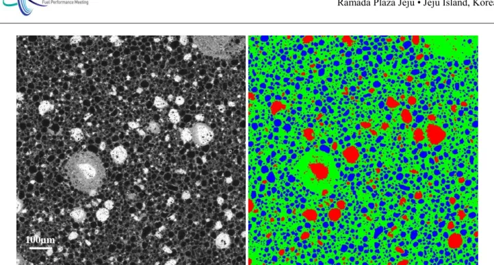
The microstructure of such type of fuel can be modelled by inclusions surrounded by a continuous matrix [4]. The fissile content of each phase is often very different which leads to a heterogeneity of burn-up distribution at the scale of the microstructure. On Fig. 1, the different grey levels of the left image are representative of the different content of fissile atoms in the microstructure. The right image shows the same microstructure after discretization in 3 phases by image processing [5]. In the frame of this work, we consider a matrix (noted 1) and two types of inclusions (noted 2 and 3).
Fig. 1: Real microstructure (EPMA measurement) and simplified microstructure after segmentation
III.A. Mechanical behavior description
The simulation of the behavior of such fuels request a two-scales modelling: modelling at the scale of the microstructure, because the heterogeneous microstructure will produce heterogeneous deformations, and a modelling at the macroscopic scale to represent the behavior of a whole fuel pellet in the fuel performance code. Homogenization processing has to be performed to link the two scales [6].
As the microstructure can be segmented into 3 phases (two types of inclusions in a matrix), it has been shown that the classical theories of homogenization in solid mechanics can be used to model both the microstructure of heterogeneous fuels as well as the constitutive laws of their constituents [7]. The resulting strain-stress constitutive law expresses finally as an internal variables formulation, the evolution of these internal variables being explicitly given as function of microstructural parameters. In addition, the prediction of this constitutive law is close to the ones given by full-fields computations [8].
The principles of this modelling are based on the Mori-Tanaka approach [9] which is a method that evaluates the average stress field in each phase of a material constituted of inclusions in a matrix. This approach has been extended to linear viscoelasticity to take into account the irradiation-induced creep that occurs in nuclear fuel [10].
Having an evaluation of the different types of strain occurring in each phase, like solid and gaseous swelling, pore shrinkage (densification), thermal strain, homogenization techniques allow to calculate the macroscopic deformation of the microstructure at the scale of the meshing of the pellet in the fuel performance code. On the other hand, this behavior law calculates the average stress field in each phase, on which the swelling in particular depends at first order. So we have both microscopic and macroscopic behavior evaluation.
III.B. Fission gas behavior specificities in heterogeneous fuels
The general principle of fission gas behavior modelling in such microstructure is that in each discrete phase, the fission gas behavior is modelled by the CARACAS model for UO2. Of course the calibration of the model parameters should be a bit different because the material in the phases is not exactly the same as UO2, but the physical phenomena represented are the same. From a strictly “fission gas behavior” point of view, the different phases represented in such a microstructure are independent one from the other.
One coupling between phases exists anyway by the source term of fission gas atoms. As a matter of fact, fission gas atoms recoil after fission and are implanted at a range about 7 µm from the fission location. So a fission gas atom produced in one phase can stop its recoil in another phase. In each phase, the global source term of fission gas atoms to be considered to represent the behavior of the fuel is the balance between fission gas atoms implanted in the phase, and the fission gas atoms implanted out of the phase. The calculation of this source term
i for each phase depends on the geometry (volume fraction xi, radii ri for inclusions), enrichment and neutronics (fission ratesF
i) of all the phases and is done analytically.If the fuel performance code in which the model is integrated contains a heterogeneous neutronics model, it provides the local fission rates (
F
i) in every phase represented. This is typically the case for the ALCYONE code. This computation scheme can also be used to provide these local fission rates as surrogate models depending on phases geometry and burn-up. These surrogate models are used to describe the heterogeneous distribution of fission gas atoms in the microstructure in the case where the fuel performance code does not have a heterogeneous description of the microstructure for neutronics. This approach is used in GALILEOTM and in CYRANO3. In CYRANO3 code the heterogeneous neutronics model is also integrated and can be used.III.C. Coupling description
As mentioned above, the fuel behavior, particularly fuel swelling, depends on the local hydrostatic stress at first order. This stress depends also on the local contrasts of deformation between the phases, including the local fuel densification which depends on the local burn-up according to the commonly used models [11], [12]. Irradiation creep rate also depends on the local fission rate which is very different one phase from the other.
CARACAS model is coupled to the mechanical model which provides on each node of the pellet meshing a mean stress in each phase that is used by CARACAS to calculate a local densification and swelling. These quantities are provided to the thermal-mechanical model until convergence of the whole system (Fig. 2).
Thermal and fracturation strains are considered homogeneous at the scale of the microstructure.
Fig. 2: Coupling scheme between fission gas behaviour and mechanical model [6]
For the moment, thermal creep that occurs at high temperature (over 1500K) in irradiated fuel and which would lead to progressive stress relaxing is not explicitly taken into account in the 3-phase mechanical behavior law. But to model this
stress relaxing, we assume that over 1500K, the local stress provided to the fission gas model CARACAS is equal to the contact pressure between the cladding and the fuel pellet. Compared to proper fuel thermal creep, it is an instantaneous representation of stress relaxing, but it leads to a good evaluation of the increase of the cladding radius during transients with holding time.
IV. RECENT RESULTS OF CARACAS MODEL FOR HETEROGENEOUS MICROSTRUCTURES
In this section, we will present the results obtained within the different applications: ALCYONE V1.4 (CEA) in which it has been developed and in the two industrial applications GALILEOTM (AREVA NP) and CYRANO3 V3.5.4 (EDF). In these last two applications, the mechanical behavior of the fuel is modelled in a homogeneous way.
IV.A. ALCYONE code (CEA)
IV.A.1. Steady-state irradiations
The model implemented in ALCYONE V1.4 with the 3-phase mechanical behavior law has been validated on about 60 MOX fuel rods in steady state conditions after calibration of some physical and numerical parameters using probabilistic methods [13]. The validation database is made of fuel rods of different microstructures and enrichments. Calculate fission gas release is in good agreement with the experimental data (Fig. 3). The admitted tolerance +/- 40% corresponds to +/- 5% uncertainty on linear heat rate.
Fig. 3: ALCYONE V1.4 fission gas release calculation versus experiment
It is also interesting to evaluate the sensitivity of the model to the lack of perfect knowledge we have on experimental conditions and material properties. For example, it is very interesting to quantify the sensitivity of the model response to the grain size of the ceramic which is a parameter of first order for the diffusion of the gas towards the grain boundary, but also for the amount of gas that can be contained on the grain boundary. We have considered an uncertainty of +/- 5% on linear heat rate during all the irradiation (at 2 standard deviations), and an uncertainty of +/- 1µm on the evaluation of the grain size. As shown on Fig. 4, the resulting uncertainty intervals cross the bisector of the graph for most of the cases. This consolidates the validation of the model regarding the available data. Most of the total uncertainty comes from the uncertainty on the average linear heat rate of the fuel rod.
Fig. 4: Uncertainty on FGR due to experimental conditions
IV.A.1. Transient cases
The model has also been validated in transient situations (power ramps [14]). Despite the simplified approach described above to represent the stress relaxing due to fuel thermal creep, the fuel rod diameter change during the ramp is well calculated (ramp at 30 GWd/tM up to 428 W/cm, 13 h holding time) as shown on Fig. 5.
Fig. 5: Fuel rod diameter change during transient (calculated and measured)
IV.B. CYRANO3 code (EDF)
The CARACAS model implemented in CYRANO3 V3.5.4 with homogeneous mechanical behavior law has been validated on about 90 MOX fuel rods in steady state conditions (PWR data) after calibration of some physical and numerical
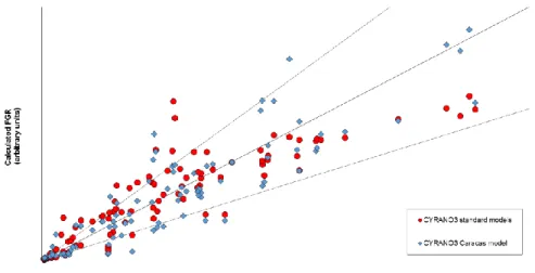
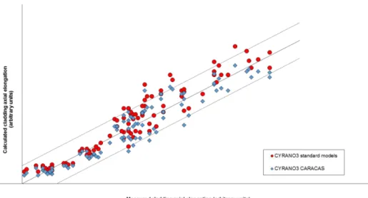
parameters. As for ALCYONE code the validation database is also made of fuel rods of different microstructures and enrichments. At this stage of the CARACAS model development, this integration is restricted to MOX fuel irradiated in steady-state conditions. Generalization to other transient conditions (power ramps) will be performed in a next future. The predictions given by the CARACAS model implemented in CYRANO3 are compared with the results of the CYRANO3 standard modeling. The CYRANO3 standard modeling is described in [15]. The next figures show the predictions of CYRANO3 code versus experimental measures, with standard (red dots) and CARACAS (blue dots) models. The following experimental measures are presented: the fission gas releases (Fig. 6), the internal pressures in rods (Fig. 7), and the cladding axial elongations (Fig. 8).
Fig. 6: CYRANO3 V3.5.4 – Fission Gas Release – Predictions of CARACAS and standard models vs Measures - The admitted tolerance is +/- 40%
Fig. 7: CYRANO3 V3.5.4 – Internal Rod Pressure – Predictions of CARACAS and standard models vs Measures - The admitted tolerance is +/- 16.5 %
Fig. 8: CYRANO3 V3.5.4 – Cladding axial elongation – Predictions of CARACAS and standard models vs Measures - The admitted tolerance is +/- 15%
The validation of CARACAS V3.0 in CYRANO3 V3.5.4, performed on a data base of 90 MOX fuel rods, shows very good predictions of the fission gas releases (Fig. 6) obviously at high burn up (i.e. for high fission gas releases). The predictions of internal rod pressures of rods (Fig. 7) are also very good. Moreover we notice a good adequacy between CARACAS and standard models. With CARACAS model, the axial elongation of the claddings are well predicted (Fig. 8), except for high axial elongations. These predictions are also lower than CYRANO3 standard models but they are in the acceptable tolerances.
IV.C. GALILEOTM code (AREVA NP)
The CARACAS model has been implemented in the GALILEOTM V1.2 fuel rod performance code. GALILEOTM is an advanced thermal-mechanical fuel rod performance code developed by AREVA NP. Based on state-of-the-art models coming from the pre-existing existing AREVA fuel rod codes COPERNIC2, CARO-E and RODEX4, GALILEOTM incorporates the latest thermal-mechanical modeling developments and improvements at AREVA NP. GALILEOTM is currently under review for licensing by the US-NRC (Nuclear Regulatory Commission).
As for CYRANO3, this CARACAS implementation in GALILEOTM has been done with a homogeneous mechanical fuel behavior law. The heterogeneous MOX fuel microstructure is only considered through power heterogeneity factors applied to the different MOX phases (3 phases for MIMAS MOX fuel) characterized by their volume fractions, grain sizes and residual as-fabricated porosities. The power heterogeneity factors are obtained thanks to external charts provided by the CEA and based on prior ALCYONE/PRODHEL calculations. At this stage of the CARACAS model development, these power heterogeneity charts partly cover the burnup and Pu content ranges required by the GALILEOTM MOX validation database. Therefore, these charts need to be complemented in a next future. Moreover, this integration is restricted to steady-state irradiation conditions and generalization to transient conditions will be performed later on (2017-18).
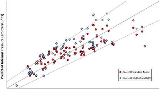
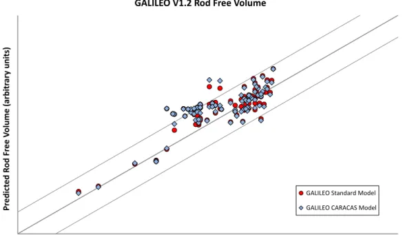
The predictions given by the CARACAS model implemented in GALILEOTM are compared with the results of the GALILEOTM standard modeling on its validation database of about 90 MOX rods. The GALILEOTM standard FGR model is originally based on the “Bernard & Bonnaud model” [16], but further improved at high linear heat generation rate and burnup thanks to a xenon concentration limit concept [17]. The next figures show the predictions of the GALILEOTM code versus experimental measures, with standard (red dots) and CARACAS (blue dots) models. The following experimental measures are presented: the fission gas releases (Fig. 9), the fuel rod internal pressures (Fig. 10) and free volumes (Fig. 11).
Calc u la ted FGR ( arbitr ar y u n its)
Measured FGR (arbitrary units)
GALILEO V1.2 Fission Gas Release
GALILEO Standard Model GALILEO CARACAS Model
Fig. 9: GALILEOTM V1.2 – Fission Gas Release – Predictions of CARACAS and standard models vs Measures - The admitted tolerance is +/- 40% Pr edict ed In tern al Pr essu re (arbitr ar y u n its)
Measured Internal Rod Pressure (arbitrary units)
GALILEO V1.2 Internal Rod Pressure
GALILEO Standard Model GALILEO CARACAS Model
Fig. 10: GALILEOTM V1.2 – Internal Rod Pressure – Predictions of CARACAS and standard models vs Measures - The admitted tolerance is +/- 18.5 %
Pr edict ed R o d Fr ee V o lume ( arbitr ar y u n its)
Measured Rod Free Volume (arbitrary units)
GALILEO V1.2 Rod Free Volume
GALILEO Standard Model GALILEO CARACAS Model
Fig. 11: GALILEOTM V1.2 – Fuel Rod Free Volumes – Predictions of CARACAS and standard models vs Measures - The admitted tolerance is +/- 2.5 cm3
From the above figures, it can be concluded that the CARACAS model implemented in the GALILEOTM code with the hypothesis of a homogenous mechanical fuel behavior law gives relevant and fairly accurate results for MOX fuel irradiated in steady-state conditions. Nevertheless, we can notice that the CARACAS FGR predictions appear to be more scattered than the GALILEOTM standard predictions with a trend to overpredict the lower FGR measurements (Fig. 9). This observation can be explained both by the power heterogeneity charts that partly cover the GALILEOTM validation database and by the specific GALILEOTM fuel creep and cracking models which strongly impact the fuel hydrostatic pressure, one of the sensitive CARACAS model parameters. These two points will need further analysis and improvements. On the other hand and despite FGR results, the CARACAS fuel rod internal pressure (Fig. 10) and free volume (Fig. 11) predictions are already satisfactory and globally in the acceptable tolerances.
GALILEO is a trademark of AREVA NP
V. CONCLUSION AND PROSPECTS
The fission gas model CARACAS has been adapted to fuels with complex microstructure, and coupled to a 3-phase mechanical behavior law. This scheme is fully operational in steady-state conditions, and some simplifications had to be done to represent the stress relaxing due to fuel creep at high temperature.
In the near future, we will take into account the fuel thermal creep in the 3-phase mechanical behavior law to better represent the progressive stress relaxing, and so better predict fuel rod evolution during either short transients (no holding time) or transients at intermediate power levels like REMORA3 for example.
REFERENCES
[1] G. JOMARD et al., “CARACAS: an industrial model for the description of fission gas behavior in LWR-UO2 fuel”,
Proc. WRFPM 2014, Sendai, Japan, Sep. 14-17, 2014, Paper No. 100154.
[2] L. NOIROT, “MARGARET: a comprehensive code for the description of fission gas behavior”, Nuclear Engineering
and Design, Volume 241, Issue 6, June 2011, 2099-2118.
[3] C. HINDMARSH, “ODEPACK, a systematized collection of ODE solvers”, Scientific Computing, R.S. Stepleman et al
(Eds.), North-Holland, Amsterdam (1983).
[4] A. BOULORÉ et al., “Advanced characterization of MIMAS MOX fuel microstructure to quantify the HBS formation”,
Nucl. Eng. Des. 281 (2015) 79-87.
[5] G. OUDINET et al., “Characterization of plutonium distribution in MIMAS MOX by image analysis”, J. Nucl. Mat. 375 (2008) 86-94.
[6] B. SECK et al., “Three scales simulations of MOX fuel rods behavior under irradiation”, communication at Nuclear Material Conference, Montpellier (France), 2016.
[7] J.M. RICAUD, R. MASSON, International Journal of Solids and Structures, 46 (2009), 1599-1606. [8] R. LARGENTON et al., Mechanics of Materials, 73 (2014), 76-100.
[9] T. MORI, K. TANAKA, Acta Metallurgica 21 (1973) 571-574. [10] Y.M. WANG, G.J. WENG, Journal of Applied Mechanics, 1992.
[11] “MATPRO -- A Library of Materials Properties for Light-Water-Reactor Accident Analysis”, US-NRC, NUREG/CR-6150 (1993).
[12] P. GARCIA et al., “In-pile densification of MOX fuel in relation to their initial microstructure”, ANS Light Water Reactor Fuel Performance Meeting 2000, Park City (USA).
[13] A. BOULORÉ et al., “Contribution of probabilistic approaches for the calibration of a fission gas release model”,
Transactions ANS Annual Meeting, San Antonio (USA), June 2015.
[14] P. BLANPAIN et al., “Recent results from the in-reactor MOX fuel performance in France and improvement program”,
Proc. International Topical Meeting on Light Water Reactor Fuel Performance, Portland (USA), March 1997.
[15] D. BARON et al., “CYRANO3 the EDF Fuel Performance code especially designed for engineering applications”, Proc.
2008 Water Reactor Fuel Performance Meeting, Seoul (Korea), October 19~23, 2008, paper No. 8032.
[16] L.C. BERNARD, E. BONNAUD, An efficient model for the analysis of fission gas release. Journal of Nuclear
Materials, (2002) 125-134.
![Fig. 2: Coupling scheme between fission gas behaviour and mechanical model [6]](https://thumb-eu.123doks.com/thumbv2/123doknet/12908908.372221/5.918.221.714.657.982/fig-coupling-scheme-between-fission-behaviour-mechanical-model.webp)