HAL Id: hal-02093136
https://hal.archives-ouvertes.fr/hal-02093136
Submitted on 8 Apr 2019
HAL is a multi-disciplinary open access
archive for the deposit and dissemination of
sci-entific research documents, whether they are
pub-lished or not. The documents may come from
teaching and research institutions in France or
abroad, or from public or private research centers.
L’archive ouverte pluridisciplinaire HAL, est
destinée au dépôt et à la diffusion de documents
scientifiques de niveau recherche, publiés ou non,
émanant des établissements d’enseignement et de
recherche français ou étrangers, des laboratoires
publics ou privés.
Simplified versus real geometry fingertip models: a finite
element study to predict force-displacement response
under flat contact compression
Jeremy Dallard, Sonia Duprey, Xavier Merlhiot
To cite this version:
Jeremy Dallard, Sonia Duprey, Xavier Merlhiot. Simplified versus real geometry fingertip
mod-els: a finite element study to predict force-displacement response under flat contact compression.
Journal of Mechanics in Medicine and Biology, World Scientific Publishing, 2018, 18 (4), 12 p.
�10.1142/S0219519418500483�. �hal-02093136�
SIMPLIFIED VERSUS REAL GEOMETRY FINGERTIP MODELS : A FINITE ELEMENT STUDY TO PREDICT FORCE-DISPLACEMENT RESPONSE UNDER FLAT
CONTACT COMPRESSION
JEREMY DALLARD
CEA, LIST, Interactive Simulation Laboratory Gif-sur-Yvette, F-91191, France
[email protected] SONIA DUPREY
Universit Claude Bernard Lyon 1, IFSTTAR, LBMC UMR T9406 F69622 Lyon, France
[email protected] XAVIER MERLHIOT
CEA, LIST, Interactive Simulation Laboratory Gif-sur-Yvette, F-91191, France
[email protected] Received (Day Month Year) Accepted (Day Month Year)
Finite element fingertip models are useful tools to assess product ergonomics. While ”real geometry” approaches provide accurate results, developing models requires medical im-ages. ”Simpified geometry” approaches have to date not been tested to see whether they can provide equally accurate results in terms of mechanical response, i.e. force-displacement response and dimensions of fingertip contact area. Four fingertip models were built either from medical images (Visible Human project) or from simplified ge-ometries. Simulations of fingertip flat contact compression at 20◦were performed. A 2nd
order hyperelastic material property was used to effectively reproduce the mechanical behavior of the fingertip. Models based on simplified geometries such as conics proved as accurate as models reconstructed from medical images. However, accurate positioning of the bony phalanx is paramount if a biofidelic mechanical response is to be reproduced. Keywords: Fingertip; Soft tissue; Finite element modeling; material properties; Hypere-lasticity
1. Introduction
In the context of human-environment interactions, the fingertips play a key role. During dexterous manipulations, fingertips are submitted to flat contact loadings up to 10 N , at various angles1,2. Numerical fingertip models submitted to such bound-aries conditions can be helpful in the field of computer aided design. Indeed, the
1
DALLARD, Jeremy, DUPREY, Sonia, MERLHIOT, Xavier, 2018, Simplified versus real geometry fingertip models: a finite element study to predict force-displacement response under flat contact compression, Journal of Mechanics in Medicine and Biology, vol18, n° 04, 1850048, DOI: 10.1142/S0219519418500483
ergonomics of a product has been proven to be linked with the peak pressure at the contact interface3. However, such models have to be both biofidelic in terms of mechanical response (force versus displacement, dimensions of the contact area, contact pressure) and in terms of geometry. Indeed geometrical differences can gen-erate peak contact pressure discrepancies up to 27%3.
Several finite element (FE) models of fingertips are described in the literature. The degree of anatomical detail varies according to the model’s application: some models include both the dermis and epidermis4, others feature a liquid phase in
the adipose tissue5 or include mecanoreceptors6. For ergonomics applications, FE models commonly use a single tissue to represent both the skin and the pulp soft tissues7,8,9. Fingertip behavior under compression is non-linear, as experimentally observed by several authors10,11,12,13: stress-strain curves from fingertip
compres-sion usually show low stress at first, followed by a major increase in stress even for small additional strains. This typical effect is called strain-hardening14, and can only
be overcome by material properties with a high-degree potential (n ≥ 2)15, even
though such non-linear behavior depends on both material properties and geometry. Geometry is tackled using two main approaches: a ”real geometry” approach3,8,9,16,17 and a ”simplified geometry” approach4,7,18. The first generally involves segmentation of medical images like MRI images3,8. This method provides
biofidelic models from an anatomical point of view, but the reconstruction process is lengthy and requires medical images with high resolution. The commonest simplified geometries are 2D ellipse cross-sectional models4,7,19. There are a few 3D models
of simplified geometry : Wu et al.20 proposed a ”smooth mathematical surface fit-ting” adaptable to digitized fingertip shapes and Yin et al.21proposed a parametric
model based on 21 measurements taken on the finger. While the advantages of 3D over 2D models have already been shown22, the 3D ”simplified geometry” models
have yet to be validated. Concerning material properties, fingertip models can refer to various behavior laws, from basic linear elasticity4,8,18 to hyperelasticity7,20,23. Since soft tissues are known to show non-linear hyperelastic behavior (also called the strain-hardening effect), hyperelastic laws should be preferred24,3. Nevertheless, complex material properties may be difficult to deal with due to the large number of parameters that need to be obtained either experimentally or by inverse simu-lations. The level of complexity required for material properties has not yet been determined.
Despite this diversity of approaches to fingertip modeling, the criteria for model choice and validation appear inadequate3,7,8,18,23. This raises the question of the
level of modeling complexity required to simulate fingertip compression with bound-ary conditions close to the loads imposed during dexterous tasks. The present study examines the simulated mechanical responses (force versus displacement and dimen-sions of the contact area) of FE fingertip models to determine whether ”simplified geometry” approaches can be as accurate as ”real geometry” approaches. An opti-mal material property for fingertip soft tissues is proposed.
2. Methods
2.1. Geometry of the models
To observe the influence of geometry on the mechanical response of fingertip models, four models of different complexity were examined: one based on a ”real geometry” approach and three based on ”simplified geometry” approaches.
• A geometrically accurate model reconstructed from images of the Visible Human project25 (V H model).
• A geometrically simplified model based on ellipsoids (Ellipsoid model). • Two geometrically simplified models based on conics (Conics1 and Conics2
models).
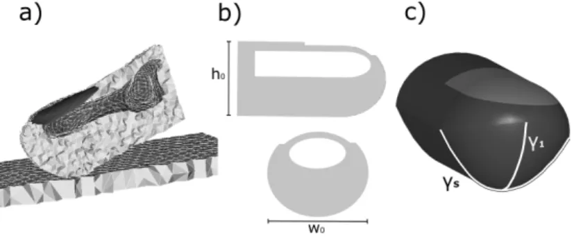
Each model had three parts: the bony phalanx, the nail and the pulp representing both the soft tissue and the skin (Fig.1).
Fig. 1. a) V H model, b) Ellipsoid model, c) Conics1&2 models
2.1.1. VH model
The V H model was built after segmentation of the bony phalanx, the nail and the outer envelope of the skin on the medical images (Fig. 1.a). Its dimensions were: height 12mm, width 16.7mm and soft tissue thickness 6.4mm. To fit the dimensions of experimental subjects’ fingertips, this model was scaled as required, using an isotropic homothety whose coefficient was defined by the finger width ratio.
2.1.2. Ellipsoid model
The external geometry of this model is based on an elliptic cylinder along the lon-gitudinal finger axis and an ellipsoid in the sagittal plane at the fingertip extremity (Fig. 1.b).
The ellipsoid parameters were chosen based on the external dimensions of the V H geometry: its height h0 and width w0. The following ratio (α = wh0
0) was then calculated. The bony phalanx is represented as an elliptic cylinder as proposed by Gerling et al.6. The dimensions and position of the phalanx were also defined to fit the V H geometry. The thickness of the nail was set at 0.6 mm as proposed by Shimawaki et al.8.
2.1.3. Conics models
For these models, the outer envelope was defined by two conics: the first was defined by the frontal curvature (γ1) and the second was defined by the sagittal curvature
(γS) (Fig. 1.c). Conics (Eq. 1) were chosen by a manuel inverse method so as to fit
a variety of fingertip morphologies.
Ax2+ 2Bxy + Cy2+ 2Dx + 2Ey + F = 0 (1)
For the Conics1 model, the phalanx was designed and positioned as for the Ellipsoid model. For the Conics2 model, the phalanx location was defined according to the method suggested by a previous study7: the bottom of the bony cylinder is placed at 42% of the fingertip height. The nail thickness was similar to that in the Ellipsoid model.
2.2. Material properties of the models
For each model, the distal phalanx was considered as a rigid body19, and the nail was
associated with a linear elastic material property (E = 170 M P a, ν = 0.30)3,5,7,8. For the material properties of the soft tissues, the simplest hyperelastic law (i.e. involving the fewest parameters) able to reproduce biofidelic behavior of the fingertip under compression loading was sought. Hyperelastic laws are generally used to model biological tissues known to be non-linear3,9,20,26,27,28. A previous
study showed that a simple first degree hyperelastic potential was not sufficient to model the non-linear behavior of the soft tissue of the fingertip29. Thus, a higher
degree potential was chosen here, starting from the second degree. A power law formulation, based on the generalized Rivlin model was considered (Eq. 2).
W = N X p,q=0 Cpq(I1− 3)p(I2− 3)q+ K 2 (J − 1) 2 (2)
A manual inverse method, based on experimental results was performed: both the Cpq coefficients and the bulk modulus were adjusted until the V H model response
(force versus displacement) was as close as possible to the experimental response10.
2.3. Mesh
Each model was meshed with linear tetrahedral elements. A convergence study seek-ing the optimal element size was performed. It determined a characteristic length of about 1 mm, which approximately corresponds to 20 000 elements per model.
2.4. Simulations and experimental data sets
Simulations were run with a finite element implicit free code (Code Aster, EDF, France). The contact was solved by a penalty method without friction, as common in the literature7,5,16,20. The penalty coefficient was chosen to avoid interpenetration. Two different experimental data sets from the literature were used in this study to 1/ determine the material property of the soft tissues of the V H model via an inverse method and 2/ validate the V H model. The first data set10 comes from index compression tests at 0◦ performed on 20 subjects; the second data set 12 is
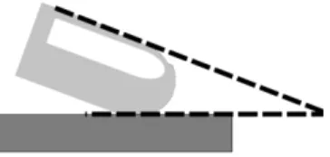
from compression tests at 20◦performed on 4 subjects. The results considered were force versus displacement (averaged over the subjects). The boundary conditions of the simulations aimed at reproducing the experimental conditions (Fig. 2). A rigid planar surface was displaced to create a contact at a given angle with the fingertip model. The bony phalanx of the finger model could not move.
Fig. 2. Schematic representation of the compression angle
The first simulations were performed with the V H model to identify the fingertip soft tissue material property and its associated parameters (inverse method based on the first experimental data set10) and to validate its mechanical response by
comparison with the second data set12.
Finally, simulations were also performed with the three geometrically simplified models at a compression angle of 20◦ (i.e. where the V H model is validated). The results in terms of force versus displacement curves and dimensions of the contact area for the 3 simplified models were compared to the results for the V H model.
3. Results
3.1. Material properties
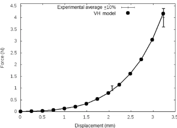
The inverse method was used with the V H model and experimental data at 0◦10 to determine the constant p and q of the generalized Rivlin model. Determining a second degree potential (Eq. 3) depending on both the first and second invariant enabled us to fit the average force versus displacement plus or minus 10% (Fig. 3).
W = C01(I2− 3) + C20(I1− 3)2 (3)
modulus of K = 200 kP a. The value obtained for the bulk modulus, typical of nearly-incompressible material behavior, approximatively corresponds to a Poisson coefficient of ν = 0.496.
Fig. 3. Force versus displacement at 0◦from Serina et al.’s experiments and from simulation with the V H model
3.2. V H model validation
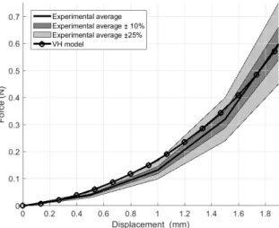
The simulated force versus displacement response at 20◦ from the V H model was compared to the experimental force versus displacement response found in the study by Wu et al.12 (Fig. 4). The V H model response fits the experimental ”average
±25%” corridor and can be considered as validated for a 20◦-compression loading
configuration. 3.3. Geometry
The Ellipsoid model dimensions fitting the Visible Human fingertip were defined in such a way that : α = 0.82. This ratio is in agreement with values from the literature, which go from 0.704 to 1.0019.
With the Conics models, the two best-fitting conics were a parabola (A = B = E = F = 0) for the sagittal curvature and a circle (B = D = E = 0) for the frontal curvature.
With the Conics1 and Conics2 models, the two different approaches to posi-tioning the bony phalanx resulted in a vertical offset of 2 mm (i.e. 2 mm less pulp for the Conics2 model).
Fig. 4. Force versus displacement at 20◦from Wu et al.’s experiments and from simulation with
the V H model
3.4. Comparison of the models
Force versus displacement results (Figure 5) showed that the response of the Conics1 model is very similar to the response of the V H model and within the ex-perimental ”average ±25%” corridor. The responses of the Ellipsoid and Conics2 models were very different from the response of the V H model and from the exper-imental average ±25% corridor. The Conics2 model was stiffer (higher forces for similar displacements), while the Ellipsoid model was less stiff.
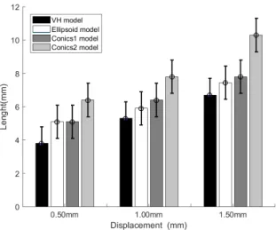
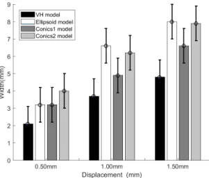
The contact area results (Figures 6 and 7) did not differentiate between the lengths predicted by the Ellipsoid, Conics1 and V H models given the ±1mm of un-certainty deriving from the element size. However, there were more discrepancies in width of contact area: from 1 mm of deflection, the Ellipsoid model over-estimated this parameter compared to the VH results. The Conics2 model over-estimated both length and width of contact area.
4. Discussion
In this study, a fingertip FE model based on realistic geometry (V H model) was used to identify a 2nd degree hyperelastic law from the generalized Rivlin model that can be applied to reproduce the non-linear behavior of the fingertip under flat contact compression. The simplicity of this law means that multiple parameters can be avoided. This is a valuable contribution to the literature, where fingertip models using hyperelastic potential can require six, ten or twelve parameters7,20,23, making
the identification of parameters based on experimental data time-consuming. The three parameters (C01, C20 and K) of this behavior law were identified in a 0◦
-Fig. 5. Force versus displacement at 20◦from Wu et al.’s experiments and from simulations with
the V H, Ellipsoid, Conics1 and Conics2 models
Fig. 6. Length of the contact area for plane contact compression at 20◦ from simulations with the V H, Ellipsoid, Conics1 and Conics2 models
compression-loading configuration. Then, this fingertip FE model was validated for a 20◦−compression configuration by comparison with experimental data. It should be noted that the term ”validation” signifies here that the model’s response fits an ”average ±25%” corridor. Since the standard deviation (std) of this experimental data set was not available, the authors chose to use an ”average ±25%” corridor30
Fig. 7. Width of the contact area for plane contact compression at 20◦from simulations with the
V H, Ellipsoid, Conics1 and Conics2 models
instead of an ”average ± std” corridor.
Three models based on simplified geometries were built. The Ellipsoid modeling approach offers the easiest implentation, requiring measurement of only the height and weight of the fingertip. The advantage of the Conics approach is that conics should be able to fit the geometry of any subject’s finger. However, the external geometry of the fingertip needs to be acquired. In a ”real geometry” approach, medical images are required. The mechanical responses of these models suggest that Conics is the only simplified approach providing results as accurate as the ”real geometry” approach. Thus, measuring the outer envelope of the fingertip and finding the conics that best fit the sagittal and frontal curvatures appears to be a mandatory step.
There were discrepancies between the Ellipsoid and Conics1 models in width of contact area. The width of soft tissue in contact increases faster for the Ellipsoid model than for the Conics1 model, generating higher width of contact area values. Yet trends for length of contact area in the Ellipsoid and Conics1 models were sim-ilar. The differences between these two models lie in their outer envelope, especially the curvatures along the sagittal and frontal planes. These curvatures determine the width of the cross-sectional tissue. Thus, our results show that the evolving width of contact area with respect to the displacement is linked to the width of the cross-sectional tissue,in contact with the plate. Taken together, these results highlight the influence of the outer envelope curvatures on the model’s outputs, and more specifically on width of contact area. These observations also point to the need to perform a sensitivity study assessing the influence of both anatomical fingertip curvatures on model simulation outputs.
Simulations with the Conics2 model showed that the position of the bony pha-lanx, and consequently the thickness of the soft tissues to be compressed, plays a very large role in the force versus displacement response. Obtaining a stiffer response for a smaller quantity of soft tissue may seem trivial. However, the authors are not aware of any studies pointing out the importance of the bony phalanx position or documenting the soft tissue thickness of the fingertip over a large population. Ex-periments providing such data are sorely needed.
The conclusions of this study are restricted to a single simulation configuration, i.e. a flat contact compression at 20◦. To confirm the benefits of a model based on conics with a 2ndorder hyperelastic law, this study should be extended to different kinds of mechanical loading (compression at a higher angle, indentation, transver-sal loading, etc.). A second limitation concerns the ±1mm of uncertainty regarding contact area dimensions (length and width). This limitation is linked to the size of the elements and could have been avoided by using smaller elements. Neverthe-less, while using this size of elements did not always lead to differentiation between models in the results (Lengths of the Ellipsoid and Conics1 models, for instance), discrimination was efficient in most cases (Length of the Conics2 model for in-stance, Widths of the Ellipsoid and Conics2 models). Finally, the models were not subject-specific and could not be compared to specific results. Future experimental perspectives include an experimental campaign involving both medical images and fingertip loading tests.
5. Conclusion
The study showed that a 2nd order hyperelastic material property can be used to
reproduce the mechanical behavior of the fingertip under compression at 20◦. In terms of geometry, care should be taken in positioning the bony phalanx within the fingertip envelope of a simplified model, since its position can greatly affect the models force versus displacement response. The performance of simplified models based on conics was comparable to models built from medical images in terms of force versus displacement response and dimensions of contact area.
Acknowledgments
Jeremy Dallard received a grant from CEA-List for this work.The authors wish to thank the National Library of Medicine for granting them access to the Visible Human Project data set.
References
1. Gonzalez F, Gosselin F, Bachta W. 2014. Analysis of Hand Contact Areas and In-teraction Capabilities During Manipulation and Exploration. IEEE Transactions on Haptics. 7:415–429.
2. Daams B. 1994. Human force exertion in user-product interaction: backgrounds for design. TU Delft, Delft University of Technology. ed. Delft, The Netherlands.
3. Harih G, Tada M. 2015. Finite element evaluation of the effect of fingertip geometry on contact pressure during flat contact. Int J Numer Method Biomed Eng. 31(6). 4. Shao F, Childs THC, Barnes CJ, Henson B. 2010. Finite element simulations of static
and sliding contact between a human fingertip and textured surfaces. Tribology Inter-national. 43:2308–2316.
5. Wu JZ, Dong RG, Rakheja S, Schopper AW, Smutz WP. 2004. A structural fingertip model for simulating of the biomechanics of tactile sensation. Med Eng Phys. 26:165– 175.
6. Gerling GJ, Rivest II, Lesniak DR, Scanlon JR, Wan L. 2014. Validating a population model of tactile mechanotransduction of slowly adapting type I afferents at levels of skin mechanics, single-unit response and psychophysics. IEEE Transactions on Haptics. 7:216–228.
7. Wu JZ, Dong RG, Rakheja S, Schopper AW. 2002. Simulation of mechanical responses of fingertip to dynamic loading. Med Eng Phys. 24:253–264.
8. Shimawaki S, Sakai N. 2007. Quasi-static deformation analysis of a human finger using a three-dimensional finite element model from CT images. J Environ Eng. 2:56–63. 9. Chamoret D, Roth S, Feng ZQ, Yan XT, Gomes S, Peyraut F. 2013. A novel approach
to modelling and simulating the contact behaviour between a human hand model and a deformable object. Comput Methods Biomech Biomed Eng. 16:130–140.
10. Serina ER, Mote CD, Rempel D. 1997. Force response of the fingertip pulp to repeated compression–effects of loading rate, loading angle, and anthropometry. J Biomech. 30:1035–1040.
11. Pawluk DTV, Howe RD. 1999. Dynamic lumped element response of the human fin-gerpad. J Biomech Eng. 121:178–183.
12. Wu JZ, Dong RG, Smutz WP, Rakheja S. 2003a. Dynamic interaction between a fingerpad and a flat surface: experiments and analysis. Med Eng Phys. 25:397–406. 13. P´erez-Gonz´alez A, Vergara M, Sancho-Bru J. 2013. Stiffness map of the grasping
contact areas of the human hand. J Biomech. 46:2644–2650.
14. Horgan CO, Saccomandi G. 2003. A description of arterial wall mechanics using limit-ing chain extensibility constitutive models. Biomech and model Mechanobiol. 1:251–266. 15. Gent AN. 2012. Engineering with rubber: how to design rubber components. Carl
Hanser Verlag.
16. Wang Z, Wang L, Ho VA, Morikawa S, Hirai S. 2012. A 3-D nonhomogeneous FE model of human fingertip based on MRI measurements. Transactions on Instrumentation and Measurement. 61:3147-3157.
17. Yoshida H, Tada M, Mochimaru M. 2006. 3D Finite Element Analysis of the fric-tional behavior of the human fingertip. Proceedings of the 28th Annual Internafric-tional Conference Engineering in Medicine and Biology Society. 91–94.
18. Maeno T, Kobayashi K, Yamazaki N. 1998. Relationship between the structure of human finger tissue and the location of tactile receptors. JSME International Journal Series C. 41:94–100.
19. Srinivasan MA, Dandekar K. 1996. An investigation of the mechanics of tactile sense using two-dimensional models of the primate fingertip. J Biomech Eng. 118:48–55. 20. Wu JZ, Welcome DE, Dong RG. 2006. Three-dimensional finite element simulations of
the mechanical response of the fingertip to static and dynamic compressions. Comput Methods Biomech Biomed Eng. 9:55–63.
21. Yin J, Gerling GJ, Chen X. 2010. Mechanical modeling of a wrinkled fingertip im-mersed in water. Acta biomaterialia. 6:1487–1496.
22. Harih G, Tada M, Dolak B. 2016. Justification for a 2D versus 3D fingertip finite element model during static contact simulations. Comput Methods Biomech Biomed Eng.,19(3):1409–1417.
23. Wu JZ, Dong RG, Smutz WP, Schopper AW. 2003b. Modeling of time-dependant force response of fingertip to dynamic loading.J Biomech. 36:383–392.
24. Harih G, Dolˇsak B. 2014. Recommendations for tool-handle material choice based on finite element analysis. Applied ergonomics.45(3):577–585.
25. Ackerman MJ. 1998. The visible human project. Proceedings of the IEEE. 86:504–511. 26. Hendriks FM, Brokken DV, VanEemeren JTWM, Oomens CWJ, Baaijens FPT, Horsten JBAM. 2003. A numerical-experimental method to characterize the non-linear mechanical behaviour of human skin. Skin Res Technol. 9:274–283.
27. Blemker SS, Delp SL. 2005. Three-dimensional representation of complex muscle ar-chitectures and geometries. Ann Biomed Eng. 33:661–673.
28. Telfer S, Erdemir A, Woodburn J, Cavanagh PR. 2015. Simplified versus geometrically accurate models of forefoot anatomy to predict plantar pressures: A finite element study. J Biomech. 49:289–294.
29. Dallard J, Merlhiot X, Duprey S, Wang X, Micaelli A. 2014. Fingertip finite element modelling-on choosing the right material property. Comput Methods Biomech Biomed Eng. 17:30–31.
30. Compigne S, Caire Y, Quesnel T, Verries JP. 2004. Non-injurious and injurious impact response of the human shoulder three-dimensional analysis of kinematics and determi-nation of injury threshold. Stapp car crash journal. 48:89-123.