Publisher’s version / Version de l'éditeur:
Vous avez des questions? Nous pouvons vous aider. Pour communiquer directement avec un auteur, consultez la première page de la revue dans laquelle son article a été publié afin de trouver ses coordonnées. Si vous n’arrivez pas à les repérer, communiquez avec nous à PublicationsArchive-ArchivesPublications@nrc-cnrc.gc.ca. Questions? Contact the NRC Publications Archive team at
PublicationsArchive-ArchivesPublications@nrc-cnrc.gc.ca. If you wish to email the authors directly, please see the first page of the publication for their contact information.
https://publications-cnrc.canada.ca/fra/droits
L’accès à ce site Web et l’utilisation de son contenu sont assujettis aux conditions présentées dans le site LISEZ CES CONDITIONS ATTENTIVEMENT AVANT D’UTILISER CE SITE WEB.
The 7th International Symposium on Virtual Reality, Archaeology and Cultural
Heritage VAST (2006) [Proceedings], 2006
READ THESE TERMS AND CONDITIONS CAREFULLY BEFORE USING THIS WEBSITE. https://nrc-publications.canada.ca/eng/copyright
NRC Publications Archive Record / Notice des Archives des publications du CNRC :
https://nrc-publications.canada.ca/eng/view/object/?id=8fbdae86-26e2-42f5-b1ae-b973d60831a1
https://publications-cnrc.canada.ca/fra/voir/objet/?id=8fbdae86-26e2-42f5-b1ae-b973d60831a1
NRC Publications Archive
Archives des publications du CNRC
This publication could be one of several versions: author’s original, accepted manuscript or the publisher’s version. / La version de cette publication peut être l’une des suivantes : la version prépublication de l’auteur, la version acceptée du manuscrit ou la version de l’éditeur.
Access and use of this website and the material on it are subject to the Terms and Conditions set forth at
Multi-Resolution Digital 3D Imaging System Applied to the Recording
of Grotto Sites: the Case of the Grotta dei Cervi
Beraldin, Jean-Angelo; Blais, François; Cournoyer, Luc; Picard, Michel;
Gamache, Daniel; Valzano, V.; Bandiera, A.; Gorgoglione, M.
National Research
Council Canada
Institute for
Information Technology
Conseil national
de recherches Canada
Institut de technologie
de l'information
Multi-Resolution Digital 3D Imaging System
Applied to the Recording of Grotto Sites:
The Case of the Grotta dei Cervi *
Beraldin, J.-A., Blais, F., Cournoyer, L., Picard, M.,
Gamache, D., Valzano, V., Bandiera, A., Gorgoglione, M.
November 2006
* published at The 7th International Symposium on Virtual Reality,
Archaeology and Cultural Heritage VAST (2006). Cyprus. October 30 -
November 4, 2006. NRC 48791.
Copyright 2006 by
National Research Council of Canada
Permission is granted to quote short excerpts and to reproduce figures and tables from this report, provided that the source of such material is fully acknowledged.
Multi-Resolution Digital 3D Imaging System Applied to the
Recording of Grotto Sites: the Case of the Grotta dei Cervi
J.-A. Beraldin1, F. Blais1, L. Cournoyer1, M. Picard1, D. Gamache1 V. Valzano2, A. Bandiera2
M. Gorgoglione3
1
IIT, National Research Council Canada, Ottawa, Ont, Canada, K1A OR6
2
SIBA Coordination, University of Lecce, LE, Italy, 73100
3
Superintendence of Archaeology of Apulia, Taranto, Italy
Abstract
The Grotta dei Cervi is a complex and fragile Neolithic cave where human presence left a large number of unique pictographs and petroglyphs. Detailed documentation necessitates recording it at different levels of details or spatial resolutions. A general approach would entail a combination of 3D data from different 3D sensors and information from different sources in order to meet set resolution targets. We used a prototype multi-resolution 3D laser imaging scanner that allowed acquiring the shape information of the three main chambers with a spatial resolution that improves with shorter standoffs. The system can record 3D data at a camera-to-object distance which ranges from 0.5 m to 10 m. At a standoff of 0.75 m, it provides a depth uncertainty of 0.08 mm and an optical lateral resolution of 0.2 mm on actual rock surfaces. This paper presents the project and the results obtained. The 10-day long visit into the Grotto generated more that 100 GB of 2D and 3D data that requires the development of new tools for modelling and managing the archive.
Categories and Subject Descriptors (according to ACMCCS): I.3.3 [Computer Graphics]: Picture/Image Generation - Digitizing and scanning
1. Introduction
1.1. High-resolution 2D and 3D information for multi-target applications
High-resolution 3D models of museum objects and heritage sites contain a wealth of information that can be examined and analyzed for a variety of conservation, research, and display applications [GBT*02]. For example, in the case of a site that must be closed or subjected to limited access for conservation reasons, an immersive 3D virtual reality theatre can be used to enable visitors to “virtually” visit the site. Researchers can magnify or zoom in on a 3D model to examine, measure, and compare fine surface details for signs of deterioration or to examine tool mark features. In contrast to photographs, the actual geometric 3D position of each point on the surface of the model is available. Computer-based visual enhancement and analysis techniques can be applied to accomplish a precise “virtual restoration” that cannot readily be accomplished using traditional conservation techniques. For example, sections of paintings that have been removed from a grotto to a distant museum can be scanned and digitally reintegrated into the site 3D model for recontextualization. Enhancement techniques can be used to improve the legibility of faded images or inscriptions as well as to remove graffiti that has defaced the images. Finally, 3D models recorded before and after an actual conservation treatment, can serve as vital archival record for ongoing site monitoring and maintenance.
1.2. General approach to accurate 2D-3D site recording
The accurate recording of rock art sites, ancient crypts and grotto sites is a challenging task. The sites have either formed naturally or been carved from the surrounding rock and typically the walls, floors, and ceilings have an irregular surface shape and the paintings (pictographs) or carvings (petroglyphs) follow the contours of the rock surface over large areas. These features particularly the shape of the rock surface and speleothems (wall concretions, stalactites) are difficult to record with a high level of detail, measure, compare and display using conventional recording techniques such as survey methods, rectified photography, distance meters, etc. There is no single method for shape and appearance recording that works for all types of environment and at the same time is fully automated and satisfies the requirements of the application. A general approach combines models created from multiple images, single images, range sensors, known shapes, CAD drawings, existing maps, and survey data [EBG*05]. The main objective is to minimize the impact of measurement uncertainties, augment the amount of information available (spatial resolution), and reduce costs and time spent on those sites.
J.-A. Beraldin et al. / Multi-Resolution Digital 3D Imaging System Applied to the Recording of the Grotta dei Cervi
. Figure 1: Grotta dei Cervi, Neolithic cave, Italy
(40°04’47”N, 18°29’02”E). Photographs showing
pictographs (Guano, Okra), petroglyphs and speleothems.
1.3. Neolithic Cave: Grotta dei Cervi, Italy
The Grotta dei Cervi project started in February 2004, and it aims at recording the shape and appearance of that cave and to push 3D technology to higher levels. The site is composed of three main corridors decorated with Neolithic pictographs made of red okra and bat guano and petroglyphs (see Fig. 1) [Gra02]. The Grotto discovered in 1970 by local speleologists is located in South-eastern Italy at Porto Badisco (40°04’47”N, 18°29’02”E), Otranto, LE. The main entrance is situated at 26 m above sea level and the largest depth is about 26 m. The Grotto contains a rich stygobitic fauna. The temperature is fairly constant at 18°C and the RH hovers between 98% and 100% [LGS*00]. The main motivation for this project comes from the fact that the cave is closed to the public and only a limited number of experts are allowed in every year. This measure is necessary in order to preserve the delicate environmental balance inside the site. Consequently, a detailed 3D model draped with colour information would allow for increased information on the site through detailed studies and virtual visits without traumatic consequences to it. Work on the central corridor measuring about 300 m long is underway (see Fig. 2). This corridor has passage ways barely allowing an adult in and some chambers have a maximum cross section of about 8 m wide × 5 m high.
1.4. Organization of paper
The objective of this paper is to review current literature on rock art 3D recording, and, present the project, an overview of the multi-resolution 3D imaging system used and the results obtained up to now. This research work is in progress because the 10-day long visit to the Grotto generated more that 100 GB of high resolution 2D and 3D data that will require the development of new tools for modelling and managing the archive. Section 2 summarizes
a number of projects aimed at documenting in 3D rock art sites. Section 3 presents details about the planning of the project. Section 4 discusses the characteristics of the prototype laser scanner and Section 5 will describe the preliminary results. This paper ends with some concluding remarks.
Figure 2: Map of the cave and illustration of the areas
completed (modified from [Gra02]).
2. Some projects on 3D recording of Rock Art sites
These examples will show the challenges in preserving record rock art sites and the increased interest in using laser scanners amongst other technique to acquire dense high resolution 3D information.
2.1. Caves and Crypts
As early as 1994, laser scanning has been used for cave recordings [Men02]. Electricité de France and Mensi undertook the modelling of the Cosquer cave that was discovered in 1985 by a diver near Marseille (France). The cave walls are decorated by paintings that are between 19000 and 27000 years old. Access to the cave is treacherous: the entry is 37 meters below the water level with a 175-meter long passage tunnel. This cave is now protected; the access is closed. The triangulation-based laser scanner was transported in a water proof case into the cave. The computer was positioned on the coast and connected directly to the scanner via a 300-meter cable. The final model was created from 28 different scanner positions, 128 images from the on-board video colour camera and took 67 work hours to create a model with 4.7 millions 3D points – resolution of 30 mm (XY) and 1 mm at 5 m (Z). In 1996, in collaboration with the Israel Antiquities Authority, NRC Canada undertook a project to demonstrate the application of a portable triangulation-based laser scanner for conservation documentation of the Arcosolia Room of the Tomb of St. James and a number of other sites in Israel [GBT*02]. The Arcosolia Room of St. James Tomb, which measures approximately 2 m x 2 m x 1.8 m, has been carved in the rock, and its interior surfaces are rough and irregular. The objective was to digitize the entire interior of the Tomb to prepare an archival record for conservation documentation. The entire interior of the Tomb was recorded at 10000 3D points per second with a lateral resolution of 2 mm (X,Y) and a depth uncertainty (Z) of 0.3 mm in one half day of on-site recording time. Subsequently, approximately 4 to 5 days were required off-site to prepare the 3D digital model.
J.-A. Beraldin et al. / Multi-Resolution Digital 3D Imaging System Applied to the Recording of the Grotta dei Cervi
In 2001, the SIBA Coordination at the University of Lecce, Italy in collaboration with NRC Canada applied a technique, which combined photogrammetry, 2D digital photography and 3D scanning to prepare a photo-realistic 3D model of the Byzantine Crypt of Santa Cristina in Carpignano, Italy for conservation documentation and visual communications [BPE*05]. The crypt excavated around the 9th century C.E., measures about 16.5 m x 10 m x 2.5 m and has a number of well-preserved frescoes on the walls. A photogrammetric technique was used for the main entrances and a commercial triangulation-based laser range scanner was used to provide 3D points at a rate of 100 points per second for the interior. Texture was acquired with a 6 mega-pixel digital camera. A total of 92 hours were spent in the Crypt to acquire about 12.8 million 3D points. The 3D spatial resolution on the walls is about 5 mm and on the ceiling and floor, 15 mm; texture resolution is 1 mm on the walls. The range uncertainty was estimated at 0.8 mm. The 3D model was created over a period of one month. A CDROM and DVD about the site along with a movie showing a virtual fly through of the Byzantine Crypt were prepared.
The Altamira cave located in Spain was a popular stop for tourists up to 1970. It was then closed because of the high number of visitors that resulted in an increase in temperature and humidity which is known to cause the prehistoric cave paintings to flake off the walls. The cave authorities decided to reconstruct the whole cave true to size so that the public could view the prehistoric paintings without risking damage to the original. A close range triangulation-based laser scanner recorded three-dimensional images of more than 2600 m² of painted walls [Min01]. Negative shapes were cut in foam and silicone moulds were made. The silicone moulds were painted by hand with natural pigments. The completed physical cave model is cooled down to 12°C to give a genuine cave experience. No indications of spatial resolution were found. Others have also been interested to laser scanning mapping in other caves around the world. In [KKC01], the authors discuss a multi sensory 3D scanning method where they achieve a fully integrated 3D model with texture that has roughly a 2 mm mesh density. In [GVI*05] the authors describe a solution for the remote fruition of a cave site based on a mobile robot. They aim at increasing both off-line and on-off-line experience of such sites with a robot that moves in the cave and collects both colour and 3D structures. They performed their experiment in the “Grotta dei Cervi” (“Stag’s Cave”) zone III. At the moment, spatial resolution and accuracy figures have not been released.
2.2. Pictographs and petroglyphs
In [EFP04], the authors present an approach to create detailed and realistic 3D models of Aboriginal pictographs of the Baiame cave in New South Wales, Australia. They used a combination of time of flight laser scanning, bundle adjustment, and surveying. The technique achieves the texture mapping without extracting common points between the texture images and the 3D geometric model. A total station was used to “tie” the data together by measuring the coordinates of points which were discernable
in the data. The standard deviations of the computed 3D coordinates were 13 mm (X), 9 mm (Y), and 11 mm (Z). In [CF05], according Chandler and Fryer, archaeologists, conservators and rock-site managers need record sites using simple and cost effective methods. They developed a methodology that enables a non-expert to acquire images suitable for photogrammetric measurement using a 3-megapixel digital camera and a scale bar. No laser scanner is necessary or desirable. At the moment, they still require expensive professional grade software and an external self-calibrating bundle adjustment to generate both accurate and dense DEMs/orthophotographs. They conducted fieldwork experiments in New South Wales, Australia where both petroglyphs and pictographs were recorded. The petroglyphs measure less than two meters in extent and the stereo imagery was captured by raising the digital camera 1 to 2 meters above the surface. A second 6-megapixel camera was used to assess the accuracy of the cheaper camera. In sharp contrast, the authors in [WSVW04] take a route based on a mid range laser scanner and GPS surveying instrument to record petroglyphs in Little Lake, CA, USA. At the moment, the topic of modelling petroglyphs by either laser scanning or photogrammetry is being revisited by many researchers around the world. The main reasons are that laser scanning is still seen as expensive, difficult to transport into the field and requires some expertise to use successfully during data capture and photogrammetry gives rather inaccurate and sparse data on featureless surfaces.
2.3. Illuminating rock art
In [Cha02], the author oriented his work to the creation of highly realistic rendered images which are based on as much real-world data as is obtainable. For the author, much research has been undertaken into accurately modelling archaeological sites and reconstructing incomplete structures. Unfortunately, the modelling of the illumination used by standard software packages for rendering tend to be based on sources that simulate daylight, and artificial sources, rather than original flame-based sources like oil lamp or candle light. It is essential that these be modelled accurately when recreating these ancient conditions. The site used to test the approach is a section of the cave at Cap Blanc, France which dates back to the Upper Palaeolithic era. The authors in [MYKI05] simulated how natural light might have illuminated the interior walls of the Fugoppe Cave, located in northern Japan which they obtained from their proposed modelling system based on short and mid range laser scanners. They examined the possibility that ancient painters and sculptors worked under natural light as opposed to what archaeologists believe that they worked using artificial lights such as torches.
3. Grotta dei Cervi: Practical considerations
A reconnaissance visit to the grotto in 2004 allowed the team to plan the activities. The main concerns were the technical difficulties the team might encounter and the determination of the required spatial resolutions. We had strict guidelines to abide to before entering the Grotto, a few are listed here
J.-A. Beraldin et al. / Multi-Resolution Digital 3D Imaging System Applied to the Recording of the Grotta dei Cervi
.
- emergency exits, equipment and first aid stations had to be determined in advance,
- drop cloths and carpet made of a resilient mesh to be used for equipment and people,
- light weight wires for electricity and commu-nication located in fixed positions,
- constantly monitor temperature during work, - two speleologists present in the grotto at all time, - no modifications allowed to the site to fit the
equipment or people.
The spatial resolution of a model depends on the level of details sought by the intended application of the 3D model but also by the equipment available and by practical and other logistic constraints. With reference to Figure 2, a list of interesting areas was considered for recording:
- Low and high-resolution 3D scans in zones III and VIII,
- Complete scanning of zones V and VII,
- Very-high-resolution 3D scanning of the Shaman of section VIII (2000 x 2000 pixels image), - Lower and medium resolution 3D scans of other
sections of the caves and passages that have less historical significance but important to create a more realistic 3D model of the site; some low-resolution scans of some floors were also done, - High-resolution texture photographs using flash
lamps according to work above,
In a few months during 2004, we put together the financing, the equipment, and complete team for the February 2005 visit. The NRC team was composed of five individuals directly involved in the project and one programmer that stayed on-line in Canada. From the SIBA-University of Lecce, five individuals participated directly to the recording inside the Grotto and one programmer that stayed on-line outside. Two experienced speleologists and two archaeologists accompanied and took an active role during the recording. The project went according to plan with minimum modifications from the original schedule even when considering the complexity and difficulty of this very challenging environment: dust, humidity, and size, etc. To limit the quantity of equipment inside the Grotto and to adapt quickly to the unpredictability of the irregularly shaded walls, we used our extensively modified prototype high resolution 3D laser imaging scanner. It acted like a three-in-one laser scanner. Section 4 will describe this prototype laser scanner. For texture acquisition, one digital camera (Kodak-14n®) with two lenses (24 mm) and four 500 watts•sec flashes were used. A low noise power generator, one UPS, two parallel electrical power lines of 300 m long: one for the 3D laser scanner, and the second for the flashes. One Ethernet link insured constant cave to surface communication, backup and data transfer between the computers. Some redundancy proved necessary and provided very smooth operation that otherwise may have jeopardized the whole project. The UPS placed outside the Grotto provided constant uniform voltage regulation
needed for the proper operation of the laser scanner which was completely isolated from the four flashes.
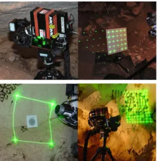
Figure 3: Photographs showing the 3D laser scanner,
calibration and resolution objects used to constantly verify and track cameras performance, virtual calibration grid for 2D camera.
4. Modelling techniques used for the project
In general, the selection of a particular 2D-3D solution must consider that the geometric fidelity depends mainly on the accuracy and data noise (measurement uncertainty-Z) and the level of surface details that can be sensed by the scanner/camera (spatial resolution-X-Y).
4.1. On the physics for optimal acquisition of shape and colour texture information
Without an understanding of the physics behind recording, most 3D acquisition and modelling methods will impose serious limitations on the final quality of the models and potential virtual interactions with them. Simply applying the typical processing pipeline used for 3D modelling will result in many cases in crude renderings of the 3D model caused by excessive filtering or polygonal compression or blurring because of poor image resolution. According to [BB06], the main reasons behind these limitations were until recently imputed to software that could not handle large models (> 50 million polygons). But today, displaying these models is being solved and one may now argue that increasing the number of recorded points or buying higher resolution imagers will solve the question of resolution. This simple answer is naive, it is hiding a more important issue which is the initial quality of the raw images being acquired; it is completely useless to over-sample if the 3D and textures are blurred to start with.
The authors in [BPE*05] present an overview of the basic theory about 3D sensing to help the reader decide on which technology to use. Blais in [Blais04] reviews many scanners on the market (prior to 2004). Interesting enough, for range between 5 m and 10 m, there are very few laser scanners available commercially that are adequate for very
J.-A. Beraldin et al. / Multi-Resolution Digital 3D Imaging System Applied to the Recording of the Grotta dei Cervi
high resolution visualization application. This span of distances represents a transition between triangulation and time of flight systems.
Figure 4: Team member and scanner at work.
Figure 5: Preliminary result of a very high-resolution scan
(X-Y: 0.2 mm spacing) performed over the Shaman in Zone VIII. The 3D image is shown without colour and using side shading from an artificial light source.
Obtaining colour texture using RGB lasers, collinear colour cameras, and perspective projection methods (texture mapping) has successfully been demonstrated [ABC04, BB06, BPE*05, GBT*02] and some of these techniques are currently being commercialized. Textures acquired by separate digital camera are registered with the geometric model using common points between the 2D image and the 3D model. This must be done for each image unless the camera is fixed to the scanner, then it may only be done once. In the latter situation, factory calibration is acceptable only if the two systems are rigidly mounted and do not require adjustments. This is valid for specific configurations such as systems with a fixed focus camera lens, usually focused at infinity for convenience e.g. in long-range laser scanners. However, for close-range measurements, this is not acceptable. The high resolution colour camera must constantly be optimized by either re-focusing the lens and/or adjusting the converging angle to better match the field-of-view of the colour camera and 3D
scanner. Increasing the number of pixels on the 2D camera certainly helps but is by far not sufficient because of the physical limitations imposed by the camera depth of field and field of view. The complex interrelations between optimal field of view, numeral apertures, focal length of the lens and physical parameters of the detector such as the number of pixels and size were investigated by [BB06]. In that reference, charts and equations are provided as guidelines to facilitate acquiring high resolution 3D and colour images. It is shown that compromises are mostly imposed by the laws of physics rather than engineering.
Figure 6: Same area but after mapping the colour
photograph (Canon-20D®) onto the 3D image.
4.2. NRC’s 3D technology
The scanner used for this project is known as “Big Scan” laser scanner. It is a research prototype system currently under development for high-resolution 3D digitization of large structures. The system allows 3D recordings at a camera to object distance which ranges from 0.5 m (camera standoff) to 10 m. At a standoff of 0.75 m, it provides a resolution of 0.08 mm on cooperative surfaces. A space qualified version of this scanner was built by Neptec design Group for inspection tasks on in-flight space shuttle missions. The use of this technology both for large-scale rock face analysis and for small-scale, detailed analysis and geo-material classification has been studied. The 3D NRC Laser Scanner system uses a green (532 nm wavelength) laser to acquire high-resolution 3D images of the surface of the object (Figure 4), a red laser marker was used to help manage the acquisition and the overlap between the images. 3D lateral resolution varies depending on the distance of measurement and the point density of the 3D images:
- 0.2 mm @ 0.75 m in the very high-resolution mode (for a 2048 x 2048 pixels images, Fig. 5-6), - 0.4 mm @ 0.75 m for the high-resolution mode
(1024 x 1024 pixels),
- 0.75 to 1.0 mm @ 1.4 to 2.0 m for the medium-resolution mode (1024 x 1024 pixels),
- 2 mm @ 2 m in the low-resolution mode (512 x 512 pixels).
J.-A. Beraldin et al. / Multi-Resolution Digital 3D Imaging System Applied to the Recording of the Grotta dei Cervi
. Figure 7: View from one end of the inside of zone VII
looking at the entrance to zone VIII. This view of zone VII is shown with independent colours for each scan. It illustrates the overlapping areas between images.
5. Preliminary results
We returned inside the Grotto in February 2005. Here, we summarize the main results obtained so far.
3D scanning
The 3D model is created by acquiring a mosaic of 3D images sections and by stitching these images by software. Overlapping areas between the 3D images is needed in order to properly align them together. The operation illustrated in Figure 7 was performed in the grotto to verify the quality of the image and pre-aligns the 3D images to avoid missing data (using IMAlign® from the Polyworks® Suite). Figure 8 shows the same area using synthetic shading (the colour information has been removed). An 8-Megapixel camera (Canan20D®) is mounted on the laser scanner (Fig.3). The camera intrinsic and extrinsic parameters are calibrated on the fly using a virtual 3D grid generated by the laser camera itself (Fig.3).
2D texture photography
As shown on Figure 9, 2D photographs of key critical sections of the grotto were acquired using a 14-Megapixel digital camera (24 mm lens focal length) at two predefined pre-calibrated positions: 2.0 m for close-ups and infinity for global image modelling. These images will be used to:
- Provide very-high resolution (4500 × 3000 pixels) colour texture mapping on the 3D models for each section of the “Grotta”.
- Good consistency in the reference colour and better uniform illumination.
- Accurate colour texture of sections of the cave that were not accessible by the laser scanner. At the moment, these high-resolution photographs must be manually mapped on a 3D object using software packages such as TexCapture®.
Figure 8: Same portion of zone VII scanned at medium and
low resolution and shown with artificial shading.
Figure 9: Team working on the photographs for the texture
of zone VIII, camera and flashes are shown.
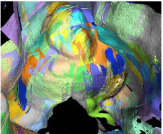
Figure 10: Preliminary result of a High-Resolution scan
made of a number of 3D images (X-Y: 0.5 mm spacing) performed in zone V.
Figure 10 shows a preliminary result obtained and illustrating the complexity of the 3D shape of the Grotto. It is important to mention that the colours were not corrected and that these images are only corrected and pre-aligned. A total of 35 GBytes for 716-3D images with photographs and 65 GBytes for 1786-high-resolution colour texture photographs were acquired.
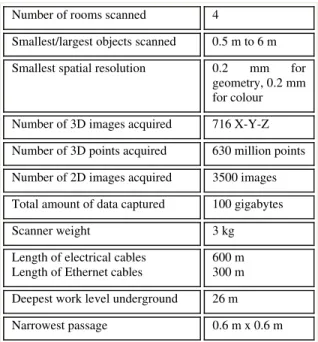
J.-A. Beraldin et al. / Multi-Resolution Digital 3D Imaging System Applied to the Recording of the Grotta dei Cervi Table 1: Project “Grotta Dei Cervi” in numbers.
Number of rooms scanned 4
Smallest/largest objects scanned 0.5 m to 6 m Smallest spatial resolution 0.2 mm for
geometry, 0.2 mm for colour Number of 3D images acquired 716 X-Y-Z Number of 3D points acquired 630 million points Number of 2D images acquired 3500 images Total amount of data captured 100 gigabytes
Scanner weight 3 kg
Length of electrical cables Length of Ethernet cables
600 m 300 m Deepest work level underground 26 m Narrowest passage 0.6 m x 0.6 m
Accurate registration of the 3D model, colour texture projection and compensation are planned for a phase II of the project. This very large amount of high-resolution 2D and 3D image data opens the door to providing a 3D model of the caves of unmatched resolution, never obtained before in any 3D model of a grotto site. This will be a major scientific milestone in modelling large and complex 3D environments. Our major challenge is associated with the size and resolution of the 3D images which causes computer crashes and excessive processing time. As a rule of thumb, the memory requirement increases linearly as the complexity of the model augment and in a quadratic manner for the processing. We are pushing the image resolution by almost an order of magnitude compared to previous work which implies that even the limits imposed by the computer operating system, for example 1.7GBytes for Windows, is becoming a major problem.
6. Conclusion
The potential of modelling as-built heritage sites opens-up promising applications. As demonstrated with the
Grotta dei Cervi project and many other projects
worldwide, a high degree of realism can be attained by those techniques. Three-dimensional models of ancient rock art sites, ancient crypts and grotto provide an important new level of documentation, which can be used for a variety of conservation, research and display applications. Perhaps the most important is that 3D VR theatre displays of accurate virtualized models of those sites can be used to enable very realistic virtual visits to the sites in lieu of actual site visits, which endanger the site itself. A second very important application is the use of the data to reliably monitor the condition and stability of the site. The problem we addressed and the approach we proposed in this paper are aimed at the effective use of 3D modelling to enhance the understanding of a heritage site that needs to be preserved and shown to more people in
order to raise awareness and understanding of rock art sites that are fragile, inaccessible and usually located in remote areas. The work will continue and we expect to do more research to create tools that will handle the models that will be created from the 100 GB of 2D and 3D data generated in the course of the 10-day visit to the grotto. Those models will be used for public outreach purposes and experts will have access to the data through collaborative projects. More research work is required to speed up the process of acquisition and modelling. These operations still require a larger amount of time. But one needs to understand that the current level of recording efforts and cost are worth spending compared to risking the forever loss of important historical sites to vandalism, natural disasters or wars.
7. Acknowledgements
The 3D recording of the Grotta dei Cervi was realized within I18 of the "Piano Coordinato delle Università di Catania e Lecce" co-financed by the European Union (FESR, PON Ricerca 2000-2006). We would like to thank L.G. Dicaire, I. Cancelliere, M. Caputo, G. Ciccarese, A. Malcangi, S. Martiradonna, F. Melcarne, S. Nuccio, P. Pulli and A. Toma through their great dedication made important contributions to this project. Financial support was also made by the town Council of Otranto (LE), the CEDAD and the Department of Beni Culturali of the University of Lecce, the Museo Provinciale of Lecce and the CASPUR of Rome.
References
[ABC04]ANDREETTO M.,BRUSCO N.,CORTELAZZO G.M.: Artifact removal in 3D textures. In Proc. CVMP ’04 (2004), V. 1, 111-117.
[BB06] BLAIS F.,BERALDIN J.-A.: Recent developments in 3D multi-modal laser imagng applied to cultural heritage. Machine Vision and Applications, in press. [BPE*05] BERALDIN J.-A.,PICARD M.,EL-HAKIM S.F., ET
AL: Virtual reconstruction of heritage sites: opportunities & challenges created by 3D technologies. In Proc. Int.
Workshop on Rec., Modelling and Vis .of Cultural Heritage, Ascona 2005, 141-156.
[Blais04] BLAIS F.: Review of 20 years of range sensor development, J. Elec. Ima., 13(1), Jan. 2004, 232-240. [CF05] CHANDLER J.H.,FRYER J.G.: Recording Aboriginal
Rock Art Using Cheap Digital Cameras and Digital Photogrammetry. In Proc. CIPA ’05 (2005), 193-198. [Cha02] CHALMERS A.: Very realistic graphics for
visualising archaeological site reconstructions. In Proc.
18th spring conf. on Comp. graphics ‘02 (2002), 43-48. [EBG*05] EL-HAKIM S.F.,BERALDIN J.-A.,GONZO L., ET
AL.: A hierarchical 3D reconstruction approach for documenting complex heritage sites. In Proc. CIPA ‘05 (2005), 790-795.
[EFP04] EL-HAKIM S.F.,FRYER J., PICARD M.: Modeling and Visualization of Aboriginal Rock Art in the Baiame Cave. In Proc. ISPRS ’04 (2004), 990-995.
J.-A. Beraldin et al. / Multi-Resolution Digital 3D Imaging System Applied to the Recording of the Grotta dei Cervi
.
[GBT*02] GODIN G., BERALDIN J.-A.,TAYLOR J, ET AL: Active Optical 3D Imaging for Heritage Applications. In
Proc. IEEE-CGA, 2002, Vol. 22, No. 5, 24-36.
[Gra02] GRAZIOSI, P.: Le pitture preistoriche della grotta
di Porto Badisco. Rist. anast. Istituto Italiano di
Preistoria e Protostoria, 2002.
[GVI*05] GRAMEGNA T., VENTURINO L., IANIGRO M., ET AL.: Pre-Historical Cave Fruition through Robotic Inspection. In Proc. IEEE Int. Conf. on Robotics and
Auto.‘05 (2005), 3187-3192.
[KKC01] KANAYA I., KADOBAYASHI R., CHIHARA K.: Three-Dimensional Modelling of Shofukuji Burial Chamber. In Proc. VSMM '01 (2001), 113-120.
[LGS*00] LAIZ L.,GROTH I.,SCHUMANN P.,ZEZZA F., ET AL.: Microbiology of the stalactites from Grotta dei Cervi, Porto Badisco, Intern. Microb. 3 (2000), 25-30. [Men02] MENSI: Cosquer Cave in Marseille. Cave
Scanning Report. In CD-ROM Cultural & Multimedia
Presentation, © Mensi 2000.
[Min01] MINOLTA EUROPE GMBH. 3D Digitizing. Altamira
II: high-tech cave reconstruction. 2001.
[MYKI05] MASUDA T.,YAMADA Y,KUCHITSU N.,IKEUCHI
K.: Sunlight Illumination Simulation for Archaeological Investigation - Case Study of the Fugoppe Cave. In:
Proc. CREST ’05, 65-72.
[WSVW04] WASKLEWICZ T., STALEY D., VOLKER H., WHITLEY D.: Terrestrial 3d Laser Scanning: A New Method For Recording Rock Art.