T.S. Argunova
Ioffe Physical Technical Institute, Russian Academy of Sciences, St. Petersburg, Russia, and Department of Materials Science and Engineering, Pohang University of Science and Technology, Pohang, Korea
M.Yu. Gutkin
Institute of Problems of Mechanical Engineering, Russian Academy of Sciences, St. Petersburg, Russia
Jung Ho Jea)and H.S. Kang
Department of Materials Science and Engineering, Pohang University of Science and Technology, Pohang, Korea
Y. Hwu and W-L. Tsai
Institute of Physics, Academia Sinica, Nankang, Taipei, Taiwan, Republic of China G. Margaritondo
Institute de physique applique´e, Ecole Polytechnique Fe´de´rale de Lausanne, CH-1015 Lausanne, Switzerland
(Received 16 March 2002; accepted 30 July 2002)
Phase-sensitive synchrotron radiation (SR) radiography was combined with x-ray diffraction topography to study structural defects of SiC crystals. The particular bulk SiC crystals examined had a low micropipe density and a hexagonal habitus composed of prismatic, pyramidal, and basal faces well developed. X-ray diffraction topography images of the sliced (0001) wafers, which were formed due to the complex lattice distortions associated with defective boundaries, demonstrated the existence of two-dimensional defective boundaries in the radial direction, normal to the (0001) planes. In particular, those parallel to the 〈112¯0〉 directions extended rather far from the seed. On the other hand, by phase-sensitive SR radiography the effect of micropipe collection was detected. Micropipes grouped mostly in the vicinities of the defective boundaries but rarely appeared between groups. Some general remarks about possible reasons for the development of such peculiar defect structures were made.
I. INTRODUCTION
Silicon carbide (SiC) attracts persistent research inter-est due to its unique electronic, thermal, mechanical, and other properties. The problem of manufacture of large-size single crystals free from structural defects, however, remains unsolved. The solution requires detailed inves-tigations of the SiC structural quality, which is sensitive to growth conditions. For nondestructive purposes, these are typically done by x-ray methods. X-ray imaging tech-niques allow the visualization of lattice defects within a crystal interior. Synchrotron radiation (SR) x-ray imag-ing has advantages caused by very high intensities and good collimations of synchrotron beams. SR diffraction topography has already allowed to show, in SiC wafers of relatively high structural quality, the generation of
hollow core dislocations, or micropipes (MPs), and the formation of other polytype inclusions.1,2
Low diver-gence of the synchrotron beam at the Stony Brook Syn-chrotron Topography Facility made it possible to establish an accurate method to simulate the pure orien-tation contrast from super screw dislocations.3 High flux and high energy of the x-ray beams available at the European Synchrotron Radiation Facility (ESRF), together with the large beam size, permitted studying the whole volume of the bulky SiC ingots.2 Moreover, special properties of the third-generation synchrotron sources, like the ESRF, opened the way to novel imaging techniques like phase contrast radiography.4,5 Being insensitive to strong deformations specific to sublimated grown SiC crystals of large area, this method allowed one to image MPs in samples of any crystalline perfec-tion.6,7 Besides the mapping and the determination of the size of the micropipes, phase-sensitive radiography provided information about their shape and spatial a)
Address all correspondence to this author. e-mail: [email protected]
distribution. Principal differences in image formation mechanisms make x-ray topography and phase-sensitive radiography complementary techniques, and investiga-tions of SiC structural quality will benefit by the use of both methods.
In this work we present such an approach to study SiC bulk crystals that were grown by the sublimation sand-wich method described in Ref. 8. A peculiar feature in the studied crystals was a well-defined hexagonal habitus composed of prismatic, pyramidal, and basal faces. The other specific attribute was a very low micropipe density observed over a large area located at a boule periphery. We report the observation of SiC defects using both strain-sensitive (topography) and density gradient sensi-tive (radiography) x-ray imaging techniques and discuss their nature and peculiarities of distribution in the crystal interior.
II. EXPERIMENTAL A. Instrumental
Phase-sensitive SR radiography experiments were per-formed at the Pohang Light Source (PLS Pohang, Ko-rea). We used the 5C1 beamline, whose 1.32-T bending magnet gives an effective source size (measured at 5.5 keV operated at 2.5 GeV) of the order of 60m in the vertical direction and 160m horizontally, at a dis-tance of 30 m from the studied sample. The experiments were performed in the edge detection regime with a sample-to-detector distance in the range from few centi-meters to 1 m. A model suggested by Margaritondo and Tromba9and verified by Hwu et al.10showed that, in this regime, image sharpening could be achieved under less stringent conditions than those used in pioneering SR phase radiography experiments.4,5Namely, on one hand, the longitudinal coherence length is not a rigid require-ment and, without too much loss of resolution, a poly-chromatic beam may be utilized. On the other hand, the requirements concerning the lateral coherence length are rather forgiving and can be fulfilled for SR beam param-eters considerably less extreme than those achievable at “long” beamlines. We used unmonochromatized (“white”) light with no optical elements except beryllium windows.
The x-ray images were detected by a slow scan charge-coupled device (CCD) camera after converting the x-rays to visible light with a thin CdWO4scintillator
crystal. Different microscope objectives were used to change the field of view between 4 × 3 mm2 and 0.6 × 0.4 mm2. The 12-bit CCD camera had a 1392 × 1040 pixels matrix size. Resolution of a few micrometers was routinely obtained. Each sequence of measurements was accomplished by a background subtraction. All im-ages displayed here are background-subtracted with no further processing.
X-ray diffraction topography investigation was done on a commercial source in one crystal set up with the Lang method in Bragg and Laue geometries by using Cu K␣ and Mo K␣ radiations. In the plane of scattering, angular divergence of the beam at the specimen was of the order of angular separation between␣1and␣2x-ray
lines. When the specimen to film distance was kept 5–10 mm, a few micrometers spatial resolution normal to the scattering plane could be achieved.
B. Samples under study
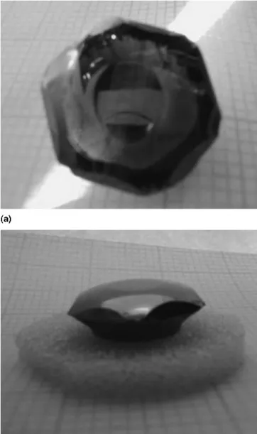
Bulk SiC crystals were grown by a sublimation sand-wich method in a tantalum container.8 Features of the boules that attracted investigation are evident in the op-tical photographs presented in Figs. 1(a) and 1(b). In pro-jection on basal plane the crystals were hexagonal in
FIG. 1. Photographs of the top (a) and side (b) views of SiC boule of hexagonal habitus.
shape with obtuse corners. The periphery of the boules exhibited remarkable prismatic faces crossed by sections of pyramidal faces, as illustrated in Fig. 2. A central part of the boule which was close to seed in the horizon-tal direction showed the lack of hexagonality (l in Fig. 2). A circular site (O in Fig. 2) parallel to the basal plane was placed just above the seed. Crystals grown by this method can be as large as 40 mm in diameter with the height up to approximately 20 mm. Note that the sample shown in Fig. 2 has an approximately 20-mm diameter. A boule near surface area (l and O in Fig. 2) was studied by x-ray diffraction topography in reflection geometry. For a further x-ray investigation the boules were sliced into wafers of a (0001) basal plane as well as (101¯0) and (112¯0) prism planes.
III. RESULTS
A. X-ray diffraction topography
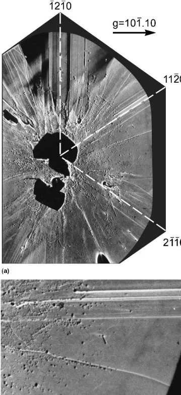
A typical example of an x-ray diffraction topograph of the (0001)-oriented wafer is shown in Fig. 3. Lines of bright contrast (high local intensity) extending out to the
wafer periphery in radial directions are visible, although their origin is not clear from the topographs alone. By correlating the positions of these lines in the wafers sliced at different distances from the beginning of growth, we suggested that they were basal plane traces
FIG. 2. Scheme of SiC crystal boule of a hexagonal habitus composed by the faces: (0001) (O); {101¯0} (m); {101¯1} (R). l is a part of the boule close to seed in the horizontal direction. Boules were sliced parallel to the planes (0001), (101¯0), and (112¯0) (n).
FIG. 3. (a) X-ray diffraction topograph of major area of (0001) SiC wafer: Lang method in Braff geometry, 101¯.10, Cu K␣, Bragg angle 35.8° (5×). (b) Higher magnification image: Lang method in Bragg geometry, 101¯.10, Cu K␣(12×). The contrast is inversed to the original image.
of two-dimensional (2D) defects, or defective boundaries. These traces were produced by diffraction contrast in both basal plane and prism plane reflections due to lattice distortions associated with the defective boundaries.
In particular, the traces parallel to the 〈112¯0〉 direc-tions, as magnified in Fig. 3(b), were visible continu-ously through several basal plane slices, indicating that the corresponding defective boundaries extended rather far from the seed. On the other hand, those defects rep-resented by curved lines in the topograph were mostly lost across the depth of one wafer. Comparing x-ray to-pographs obtained in the reflection and transmission ge-ometries, such as shown in Fig. 4(a) and 4(b), from the part of the sample displayed in Fig. 3, reveals that these two types of defects indeed differ from each other. The marked traces [Fig. 4(b)] clearly visible in the transmis-sion topograph while invisible in the reflection mode imply that the related boundaries are local.
The spotlike contrasts, as can be seen from the reflec-tion topograph in Fig. 3, are another type of defect, which can be correlated with hollow-core screw dislocations or micropipe defects. Their distribution primarily concen-trated in the central, close-to-seed area. A large area over the wafer periphery, on the other hand, was almost free from such diffraction spots [Fig. 3(b)]. With scanning electron microscopy etch pits associated with hollow-core screw dislocations in molten KOH treated wafers (data not shown) were observed in a very similar distri-bution. The dislocation density was found high in the central area but decreased with distance from the center. The density was also high close to the traces of the〈112¯0〉 defective boundaries with little in between. The resemblance therefore strongly suggested that spot-like contrasts we observed in the topograph were those micropipe defects.
The central part of the image [Fig. 3(a)] shows no contrast due to other polytype inclusions disoriented rela-tive to the main lattice.
B. Phase-sensitive SR radiography
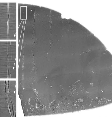
Direct evidence for the distribution of tubular-shaped defects in crystal interiors was obtained by SR radiogra-phy. By this technique the wafers sliced at different dis-tances from the seed parallel to (112¯0) and (101¯0) crystal planes were examined. Figure 5 shows the map of de-fects in the (112¯0)-oriented wafer cut, i.e., parallel to the micropipes and the direction normal to the basal plane traces of the far-reaching 2D defective boundaries, from
FIG. 4. (a) Reflection and (b) transmission topographs of the sample shown in Fig. 3: (a) Lang method in Bragg geometry, 101¯.10, Cu K␣ (6×); (b) Lang technique in Laue geometry, 112¯0, Mo K␣, Bragg angle
a central part of the boule. The most striking features are the defects vertically aligned in the central part of the sample (it should be noted that the radiograph presents only half of the wafer whose central region corresponds to the left-hand section of the image). As demonstrated in the left three figures that are the representative images magnified from the white square on top, this feature shown in the phase-sensitive radiograph resulted from closely spaced or interweaving tubular-shaped defects of approximately 10m in diameter. We call such bundles of micropipes here “superpipes.” Increase or decrease in the image intensity of this feature was attributed to the depth variation of their sites under the wafer surface. The existence of the superpipes suggested that micro-pipes bundled into groups and interacted11near the cen-ter of the boule. Such micropipe bundling effect will be further discussed in Sec. IV.
The lower part of the image (Fig. 5) provides the view of macrodefects distribution over the close-to-seed area. IV. DISCUSSION
Diffraction topographs and phase-sensitive radio-graphs of the defects in (0001)-, (101¯0)-, and (112¯0)-oriented slices provide complementary information on the structure and possible nature of these defects. If the 2D defective boundaries that were parallel to the [112¯0] direction and extended rather far from the seed [Fig. 3(a)] were perpendicular to the basal plane, the projection of the defective boundaries onto the (112¯0) plane would have a coincident edge at the hexagonal [0001] direction. That was the direction in which micropipes gathered in groups.
Due to the known distortion associated with the de-fective boundaries, one would expect that the driving force for the collection of micropipes is the accommo-dation of the lattice shear. Such transformation of micropipes to superpipes could therefore occur via coa-lescence, which, under these conditions, could be ener-getically favorable.
A micropipe can be considered as not only a super-screw dislocation having a Burgers vector but also as a tube having a free surface.11 When two pipes interact, they always attract each other, on the one hand, due to micropipe free surfaces, regardless of Burgers vector signs. This force varies with distance as approximately 1/r3.11On the other hand, the dislocation components are repelling or attractive depending on their Burgers vector signs, repelling (attractive) for the same (opposite) signs. The force varies with distance as approximately 1/r.12In dislocation theory, the first (approximately 1/r3) type is called a short-range interaction, while the second (ap-proximately 1/r) type is a long-range interaction.12 Mi-cropipes with Burgers vectors of opposite signs attract each other due to both types of interaction, resulting in
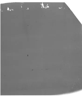
their coalescing. Meanwhile those with Burgers vectors of the same signs would interact in a more complicated manner. Nevertheless, one can still expect some equilib-rium distance exists where the repelling force due to the long-range interaction is equal to the attractive force due to the short-range one. This distance is rather small and of the order of an average radius of interacting micro-pipes. For smaller distance, the short-range attracting force prevails and the micropipes coalesce. It is also pos-sible that the long-range repelling force is suppressed by an “external” (with respect to this micropipe pair) shear stress due to residual thermal strains or other defects (micropipes, inclusions, internal boundaries, etc.). Gath-ering of a large amount of micropipes near the center of the boule and the 2D boundaries, which was attributed to higher defect density, resulted in the wafer regions be-tween the group almost free from micropipes, as illus-trated in Figs. 3 and 5. Meanwhile, in the wafers sliced far from the seed, micropipes were scarce. Figure 6 shows the example of the microradiograph demonstrat-ing the defects in a (101¯0)-oriented sample cut far from the central part of the boule. In this area micropipes were practically absent. The macrodefects seen on top were due to heavily damaged crystals containing frac-tions of material that were recrystallized by a spontane-ous growth in the cell between the holder and the back side of the seed—the process scrupulously described in Ref. 8.
V. CONCLUSIONS
Our x-ray imaging investigation by the combination of topography and phase-sensitive radiography techniques revealed that the distribution of structural defects in the SiC crystals studied here had the following special fea-tures: the 2D boundaries parallel to the directions〈112¯0〉 were associated with strong lattice distortions inside crystal interior and served as traps for micropipes. A fine structure of such regions still remains unclear. Not know-ing defect arrangements, one can hardly hope to find mechanisms for their formation. Thus, in this section we present some general considerations calling for further investigation.
Specifically, we found the existence of the planar de-fective boundaries collecting the micropipes. We were also able to map their distribution and orientation. Armed with this information, it would be much easier to propose a suitable model for the growth and therefore understand the origin of the defects.
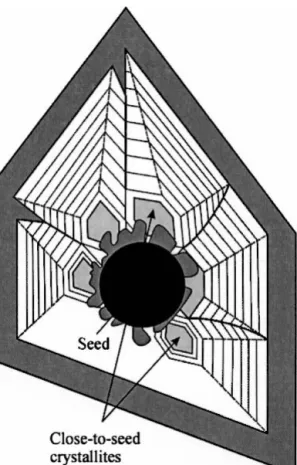
One could suppose that the growth of a hexagonal SiC crystal on a cylindrical seed started from multiple nu-cleation. With time, the nuclei appeared to be enclosed by a set of crystallites. The crystallites would finally come in contact and merge together leaving boundaries
inside the crystal body. A scheme illustrating the possible process of the formation of internal boundaries between close-to-seed crystallites is shown in Fig. 7. Thick solid lines trace the defective boundaries emerging at the joints between individuals. Interfacial regions between the merging crystallites were certainly imperfect, and crys-talline defects were then generated to relax lattice strain. Specifically, the shear component could be accommo-dated by superscrew dislocations, or micropipes. The un-derlying mechanism of the bundling effect of the micropipes and their interaction with the planar defective boundaries however remains uncertain.
The investigation of the region close to the outer sur-face of the boule (l in Fig. 2) by diffraction topography in reflection geometry did not reveal the defective bound-aries. It is likely that the joints were buried inside the crystal.
The importance of these problems is not confined by the scope of the present study. Sublimation-grown SiC crystals can contain internal boundaries of different types: between other polytype inclusions; between a re-crystallized segment and a matrix; between a matrix and a void. The explanation of the evolution of micropipes in the lattice disturbed by these defects would be an impor-tant issue.
In summary, the combination of diffraction topogra-phy and phase-sensitive radiogratopogra-phy has revealed that the micropipe defects are concentrated near internal boundaries buried inside the crystal interior, diminishing their average density in SiC wafers. This information, difficult to obtain with other techniques, is likely to pro-vide a useful clue to the defect formation and the growth of SiC large crystals.
ACKNOWLEDGMENTS
The authors are greatly indebted to Prof. Yu.A. Vodakov, Dr. E.N. Mohkov, and Dr. A.D. Roenkov, from the Ioffe Physical-Technical Institute of the Russian Academy of Sciences (St. Petersburg, Russia), for making available the SiC single-crystal samples. J.H.J. acknowledges the support by the BK21 project and by the Korea Institute of Science and Technology Evaluation and Planning (KISTEP) through the National Research Laboratory (NRL) project. T.S.A. acknowledges the support by the KISTEP through the Korea–Russia joint R&D program. REFERENCES
1. M. Dudley, X.R. Huang, W. Huang, A. Powell, S. Wang, P. Neudeck, and M. Skowronski, Appl. Phys. Lett. 75, 784 (1999). 2. E. Pernot, P. Pernot-Rejmankova, M. Anikin, B. Pelissier, C. Moulii, and R. Madar, J. Phys. D: Appl. Phys. 34, A136 (2001). 3. M. Dudley, X.R. Huang, and W. Huang, J. Phys. D: Appl. Phys.
32,A139 (1999).
4. A. Snigirev, I. Snigireva, V. Kohn, S. Kuznetsov, and I. Schelokov, Rev. Sci. Instrum. 66, 5486 (1995).
FIG. 7. Scheme illustrating a possible formation of internal bound-aries (solid lines) between crystallites resulting from a multiple nu-cleation on the seed.
5. P. Cloetens, R. Barrett, J. Baruchel, J-P. Guigay, and M. Schlenker, J. Phys. D: Appl. Phys. 29, 133 (1996).
6. T.S. Argunova, J. Baruchel, and J. Ha¨rtwig, in IEEE 10th
Inter-national Conference Proceedings (SIMC-X), Berkeley, CA (IEEE,
Piscataway, NJ, 1998), p. 287.
7. S. Milita, R. Madar, J. Baruchel, M. Anikin, and T. Argunova, Mater. Sci. Eng. B61–62, 63 (1999).
8. Yu.A. Vodakov, A.D. Roenkov, M.G. Ramm, E.N. Mokhov, and Yu.N. Makarov, Phys. Status Solidi (B) 202, 177 (1997).
9. G. Margaritondo and G. Tromba, J. Appl. Phys. 85, 3406 (1999). 10. Y. Hwu, H.H. Hsieh, M.J. Lu, W.L. Tsai, H.M. Lin, W.C. Goh, B. Lai, J.H. Je, C.K. Kim, D.Y. Noh, H.S. Youn, G. Tromba, and G. Margaritondo, J. Appl. Phys. 86, 4613 (1999).
11. M.Yu. Gutkin and A.G. Sheinerman, Phys. Status Solidi (B) 231, 356 (2002).
12. J. Hirth and J. Lothe, Theory of Dislocations (John Wiley, New York, 1982).