HAL Id: hal-02929166
https://hal.umontpellier.fr/hal-02929166
Submitted on 27 Nov 2020HAL is a multi-disciplinary open access
archive for the deposit and dissemination of sci-entific research documents, whether they are pub-lished or not. The documents may come from teaching and research institutions in France or abroad, or from public or private research centers.
L’archive ouverte pluridisciplinaire HAL, est destinée au dépôt et à la diffusion de documents scientifiques de niveau recherche, publiés ou non, émanant des établissements d’enseignement et de recherche français ou étrangers, des laboratoires publics ou privés.
Modifications of MXene layers for supercapacitors
Yachao Zhu, Khalil Rajoua, Steven Le Vot, Olivier Fontaine, Patrice Simon,
Frédéric Favier
To cite this version:
Yachao Zhu, Khalil Rajoua, Steven Le Vot, Olivier Fontaine, Patrice Simon, et al.. Mod-ifications of MXene layers for supercapacitors. Nano Energy, Elsevier, 2020, 73, pp.104734. �10.1016/j.nanoen.2020.104734�. �hal-02929166�
Modifications of MXene Layers for Supercapacitors
Yachao Zhu,1,2,3 Khalil Rajouâ,1,3 Steven Le Vot,1,3 Olivier Fontaine,1,3 Patrice Simon2,3 and Frédéric Favier1,3 1 Institut Charles Gerhardt Montpellier (ICGM), UMR 5253, Université de Montpellier, CNRS, 34095
Montpellier Cedex 5, France
2 CIRIMAT, Université de Toulouse, CNRS, INPT, Université Paul Sabatier, 118 route de Narbonne,
31062, Toulouse, France
3 Réseau sur le Stockage Electrochimique de l’énergie (RS2E), FR CNRS 3459, France
Abstract
The re-stacking of Ti3C2Tx-MXene layers has been prevented by using two different approaches: a facile
hard templating method and a pore-forming approach. The expanded MXene obtained by using MgO nanoparticles as hard templates displayed an open morphology based on crumpled layers. The corresponding electrode material delivered 180 F g-1 of capacitance at 1 A g-1 and maintained 99 % of its
initial capacitance at 5 A g-1 over five thousand charge-discharge cycles. On the other hand, the MXene
foam prepared after heating a MXene-urea composite at 550°C, showed numerous macropores on the surface layer and a complex open 3D inner-architecture. Thanks to this foamy porous structure, the binder-free electrode based on the resulting MXene foam displayed a great capacitance of 203 F g-1 at 5 A
g-1 current density, 99 % of which was retained after five thousand cycles. In comparison, the pristine
MXene –based electrode delivered 82 F g-1, only, in the same operating conditions. An asymmetric device
built on a negative MXene foam electrode and a positive MnO2 electrode exhibited an attractive energy
density of 16.5 Wh kg-1 (or 10 Wh L-1) and 160 W kg-1 (or 8.5 kW L-1) power density. Altogether, the
enhanced performances of these nano- engineered 2D materials are a clear demonstration of the efficiency of the chosen synthetic approaches to work out the re-stacking issue of MXene layers.
Keywords
MXene, foam, layer modification, pseudocapacitive behavior
In the wake of graphene1, other two dimensional materials2, such as, δ-MnO2 3, 4, 5, MoS
26, 7and MXene8, 9,
10, have received a surge of interest from the material science community, as they offer, together with their
unique “planar” physical peculiarities, an infinite number of surface chemistry opportunities, especially when compared with their carbonaceous flagship.11 These opportunities have been explored in many
application fields including electrochemical energy storage.12-14 In the corresponding devices, both basal
planes and defected edges are usually contributing to charge storage.15 As a result, one can take profit of
the strong in-plane covalent bonding and weak out-of-plane Van der Waals interactions between layers16,
to develop chemical strategies to provide or tune further active sites. These proceed by many chemical and physical methods including exfoliation17, intercalation18 and hybridization19. The main idea is to prevent
the natural tendency of the individual 2D layers to restack to minimize the surface energy just as in the pristine material(s). By chemical engineering at the nanoscale, associating layers of 2D materials of different chemical compositions and physical properties offers wonderful opportunities to take advantage of resulting synergistic effects20. Potential combinations are unnumbered, imagination is probably the limit.
As such, in the resulting composite, expanded, hybrid… materials, the opened 2D space between the layers can, for example, provide a “path” strongly suited for ion adsorption and transport. These characteristics have made 2D materials as very attractive electrode materials in batteries21 and
supercapacitors22. Two different kinds of supercapacitors (SC), can be distinguished, on the basis of the
corresponding charge storage mechanism: electrostatic interactions in electrical double layer capacitors (EDLCs), and fast redox reactions near the surface material in pseudocapacitors.23With 2D materials, this
classification remains as graphene is probably mostly EDLC type while exfoliated MnO2 birnessite is
pseudocapacitive.24-29 Composites obtained by stacking of EDLC and pseudocapacitive, EDLC and battery type, or battery type and pseudocapative 2D materials have been recently reported.30-33 However, the anisotropy of material properties could also be a critical drawback for 2D materials, especially in energy storage electrode materials. Although, both in-plane ionic and electronic conductivities can be remarkable, through-plane conductivities can be fairly limited. Depending on the layer orientation toward the current collector surface, perpendicular or parallel, electrode overall performance can be down-graded.
MXene34, as a remarkable 2D material, containing a conductive carbide core along with transition metal
researches in the field of energy storage and more specifically for supercapacitors.36-40 MXene is prepared
from the corresponding MAX phase by a chemical etching method, usually using a fluorine-containing solution. MAX phases are layered ternary carbides and nitrides with the formula Mn+1AXn, where M is an
early transition metal (such as Ti, V and Nb), A is an element from A-group (usually Al or Si) and X is carbon and/or nitrogen.8,41,42 Ti
3C2Tx-MXene could be obtained by etching Ti3AlC2 in a mixture of LiF and
HCl. Tx stands for the termination moieties at the layer surface. Their chemical nature depends on the
etching process. They have a strong impact on the electrolyte/electrode interface especially through the hydrophilic/hydrophobic surface balance. Ti3C2Tx-MXene also shows up to ≈ 6700 S.cm-1 of metallic
conductivity which is highly favorable to fast electron transfer.43-45However, as for other 2D materials, the
MXene flakes tend to restack during the preparation process, resulting in a drastic loss of the developed electroactive surface area, and hindering the electrolyte ion access into the electrode bulk15. To prevent
this re-stacking issue and simultaneously enhance the through-plane ionic conductivities, alternative methods based, for instance, on the modification of the layer morphology and texture have to be considered.
In this study, exfoliated Ti3C2Tx-MXene was first prepared by a chemical etching method from Ti3AlC2
corresponding MAX phase. To prevent the re-stacking of the resulting individual layers, several routes were explored. First, nano-sized MgO particles were used as solid spacer. After removal of the particles adsorbed at the layer surface, electrolytic ions were able to be efficiently transported in between the layers of the resulting expanded MXene during the charge-discharge process. Therefore, prepared expanded MXene (EM) electrodes showed enhanced electrochemical performances when compared to regular MXene. Alternatively, urea was used as molecular spacer or template. After a thermal treatment under argon atmosphere, a Ti3C2Tx-MXene foam (MF) was obtained. The resulting MF electrode showed an
attractive and seriously improved capacitance performance, especially at high rate. When associated to a MnO2 positive-electrode in an MF//MnO2 asymmetric device, an attractive energy density of 16.5 Wh kg-1
(or 10Wh L-1) was obtained at 160 W kg-1 (or 8.5 kW L-1) power density.
Preparation of MXene-Ti3C2Tx suspension and pure MXene: 1 g LiF (Sigma, 99.98%) and 20 ml 9 M HCl
(Sigma, 37%) solution were mixed in a plastic beaker and stirred for a few of minutes. 1 g Ti3AlC2 powders
was then slowly added to the solution. The reaction temperature was kept at 35 °C for 24 h under constant stirring. The resulting Ti3C2Tx flakes were washed with water and separated by centrifugation until the pH
value was ~ 6. The flakes were dispersed in 250 ml H2O and treated by sonication for 1 h. Finally, the
resulting Ti3C2Tx was recovered by a 1 h centrifuge step at 3500 rpm. The average size of resulting
MXene flakes is centered at 0.2 and 2 µm (Fig S1). The pure MXene film was prepared by a simple vacuum filtration procedure on a PTFE membrane by using 3500 rpm rotating speed.
Preparation of expanded MXene by hard templating method: 23.26 ml Ti3C2Tx MXene suspension (50 mg,
2.15 mg/ml) were dispersed in 26.74 ml, 200 mg MgO (Sigma, nanopowder ≤ 50 nm particle diameter) solution, and the solution was stirred for 24 h. During the filtration process, 40 ml, 3 M acetic acid (Sigma, 99.8%) were slowly added to remove the MgO template. After washing three times with pure water, the film was dried at 50 °C under vacuum.
Preparation of the MXene foam and overlapped MXene foam: 23.26 ml Ti3C2Tx MXene suspension (50
mg, 2.15 mg.ml-1) was mixed with 23.26 ml urea (Sigma) solution (200 mg with or without 0.1 M HCl).The
resulting solution was stirred for 2 h. A thick disk was obtained by vacuum filtration. After drying it at 50 °C under vacuum, the resulting film was placed in a porcelain crucible and treated at 550 °C for 2 hours under argon atmosphere.
Preparation of MnO2: 0.1272 g MnCl2 (Merck Schuchardt, anhydrous) was dispersed in 20 mL H2O under
continuous stirring. The same was done with 0.24 g KMnO4 (Sigma, 99.0%). The KMnO4 solution was
slowly added to MnCl2 solution. The resulting mixture was heated at 100 oC and kept for 6 h at this
temperature under constant stirring. After filtration and rinsing with water, the powder was obtained by drying at 80 oC overnight. From the XRD pattern, the prepared powder was assigned to -MnO
2 (Figure
S2). Corresponding SEM and TEM images are depicted in Figures S3 and S4, respectively.
Material characterization: The crystal phase and structure of the prepared material films were examined by X-ray diffraction (XRD) using a Phillips X’Pert diffractometer with Cu Kα radiation (λ=1.5405Å). Morphologies were imaged by using a JEOL JSM-6300F scanning electron microscope (SEM). The
element composition was analyzed by Energy-dispersive X-ray spectroscopy (EDX) in SEM. The thermal decomposition of MF was followed by thermo-gravimetry coupled mass-spectrometry (TG-MS) under Ar from room temperature to 800 °C (rate 5 °C/min).
Electrochemical characterization: Electrochemical measurements were performed in three electrode systems, symmetric device and asymmetric at ambient temperature by using a VMP3 multi-channel Bio-Logic electrochemical workstation. In three-electrode system, platinum foil and Hg/HgO/OH- electrode
were used as counter and reference electrode respectively. The working electrode was assembled by two clean nickel foam with sandwiched binder-free MXene film in between two stainless steel under 10 Mpa for 30 seconds. Finally, the system was tested in 1 M KOH electrolyte. In the symmetric device, two identical working electrodes were prepared as follows. The electrode was prepared by mixing the active material, carbon black and Polytetrafluoroethylene (PTFE) with a mass ratio of 60/30/10. The mixture was dispersed in a proper volume of ethanol under constant stirring. Then, the mixture was evaporated at 60 °C to get a slurry. With the adapted behavior, the slurry was rolled and, when dry, pressed in between two stainless steel under 10 Mpa for a few tens of second. Finally, the cut suitable film was assembled into the Swagelok device. For asymmetric device, MnO2 was used as a positive electrode. For individual
electrodes, capacitances are relative to the mass of active material while for devices, they are relative to the cu;ulative mass of active materials in both electrodes.
Results and discussion
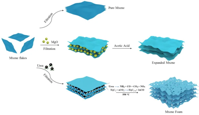
Figure 1. Synthesis scheme of the preparation of various forms of MXene, as re-stacked material after exfoliation
(top), expanded MXene after re-stacking in presence of MgO nanoparticles (middle), and MXene foam from thermal treatment in presence of urea (bottom).
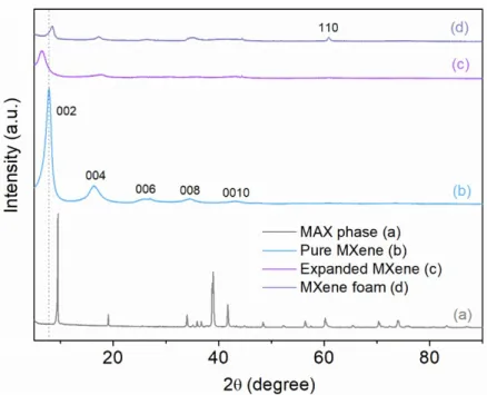
The specific synthetic routes are depicted in Figure 1. A suspension of exfoliated MXene flakes was first prepared as described in the experimental section (see Experimental details below). In the present study, it was used as starting material for the preparation of other MXene-based materials. The drastic changes in the corresponding XRD patterns shown in Figure 2 are a crystallographic proof of the conversion of Ti3AlC2 MAX phase (Fig. 2a) to MXene (Fig. 2b). As usually observed for 2D materials, only the peak
series characteristic of the layered structure of MXene remains after conversion while the other peaks, especially at about 39° 2, disappear. An inter-layer distance of 11.15 Å was calculated for the prepared MXene from the 2 position of the (002) diffraction peak at 7.87° 2. From Ti3AlC2 MAX phase (Fig. 3a) to
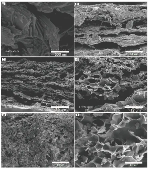
MXene (Fig. 3b), the more open and disordered 2D morphology is also evidenced by looking at the corresponding SEM micrographies.
Figure 2. XRD patterns of Ti3AlC2 MAX phase (a), MXene (b), Expanded MXene (c), and Mxene Foam (d).
To prevent the re-stacking of the MXene layers and eventually to get an even more open 2D structure, magnesium oxide was considered as a solid nano-spacer (Fig.1, middle). Such a hard template has already been used for the preparation of carbons with hierarchical porosities including activated or doped carbons, graphene...46,47,48 It appears as suited for this purpose as it is easy to prepare and/or
commercially available as nanoparticles that efficiently absorb material precursors, either in molecular, polymeric or solid states, through Van der Waals interactions and hydrogen bonds. Moreover, as such a template, it can be easily removed using a mild acidic post-treatment. MgO particles were first homogeneously dispersed in the suspension of Ti3C2Tx-MXene flakes by ultrasonication and vigorous
stirring. Once the composite suspension filtrated, MgO nanoparticles are randomly and uniformly distributed in between the MXene layers. Commercial MgO particles were actually chosen for their diameter below 50 nm to fit the MXene flake size distribution (at 0.2 and 2 µm, Fig S1). This flake/particle size ratio promoted a consistent 2D sandwich composite structure build on flakes large enough to cover “many” particles instead of a simple/single particle wrapping that would restrain the development of the targeted expanded framework. Afterwards, MgO particles were slowly “digested” by gently pouring an
acetic acid solution, and progressively washed away. The resulting film of expanded MXene was recovered after washing and drying. When comparing the XRD pattern of the expanded MXene as shown in Figure 2 with that of the exfoliated MXene used as precursor, the structural impact of the MgO hard templating is obvious: While the MXene layered structure remains, despite a severe amorphization of the material related to the loss of the long range order, a strong shift of the (002) peak towards lower angles is observed (Fig. 2c). As such, the interlayer distance increases from 11.15 to 13.60 Å along the c-axis thanks to hard templating with MgO nanoparticles.
Figure 3. Side views from SEM images of Ti3AlC2 MAX phase (a), Ti3C2Tx-MXene (b), Expanded Ti3C2Tx-MXene (c, d)
and Ti3C2Tx-Mxene foam (e, f).
SEM images in Figures 3 (c, d) show the side view of the prepared expanded MXene. The complex structure is built on large voids in between crumpled MXene layers. While voids are originating from the
dissolution of MgO nanoparticles by acidic treatment, layer crumpling could be assigned to the mechanical stress induced by capillary forces during material drying. The resulting open 3D architecture, with interconnected channels and conductive walls, is anticipated to promote suitable ion diffusion and electronic percolation through the whole material volume.
On the other hand, urea has been widely used as a reactant to synthesize N-doped materials through a pyrolysis process, including nanostructured metal oxides49, carbides50, carbons51,52, etc. Although, such a
doping is a conventional strategy in semiconductor processes, it has been more recently introduced in the synthesis of energy conversion and storage electrode materials, for oxygen reduction53, supercapacitors54
or LiS batteries55, leading to enhanced electrochemical performances and stability. After mixing the
Ti3C2Tx-MXene with urea, a thick disk was obtained by vacuum filtration. The re-staking of MXene layers is
prevented by urea molecules trapped in between. In such a slightly acidic medium, cationic protonated urea strongly absorbs at the negatively charged MXene flakes and the layers are efficiently kept apart when going to solid state. The resulting MXene@urea composite material was pyrolyzed at 550 °C under argon atmosphere. All synthetic details are given in the experimental part above. SEM micrographies of the pyrolized Mxene@urea composites are depicted in Figure 3e, 3f and Figure 4b to 4d. Although the side view (Fig.3e and 3f) is characteristic of the opening of the structure of the material induced by the synthetic process, the layered morphology of the pristine MXene (Fig. 3b) is hardly identified in the resulting disordered honey-comb structure. Moreover, discrepancies in the top views in Figure 4 of MXene and the resulting material are spectacular. While MXene shows a flat and “plain” surface build on Ti3C2Tx
layers (Fig.4a), the pyrolysis of MXene/urea composite obviously generate numerous macro-pores through the layers, i.e. perpendicular to the surface (Fig.4b-4d). The resulting 3D structure based on a disordered self-assembling of exfoliated and porous layers displays a complex foam architecture. When comparing with the pristine MXene, the (002) peaks of MXene Foam (MF) slightly shift towards greater 2 angles, suggesting a decrease of the inter-layer distance induced by the synthetic process (Fig.2d). Such a shrinking can be assigned to the de-intercalation of H2O molecules during the thermal treatment, either
free or solvating urea molecules, originally trapped in between the MXene layers. Moreover, during the process, MXene flakes are self-assembling as a foam structure by a pore-forming process that is confirmed by the appearance of a (110) peak at about 60.85° 2. This peak is characteristic of the
ordering induced in the non-basal directions. Meantime, as confirmed by the (002n) peaks, some c-axis ordering remains.56
Figure 4. The SEM images of pristine MXene (a) and MXene Foam (b-d) surface view.
As already mentioned, many authors have reported on the use of urea to N-dope various materials including carbons and carbides. To the best of our knowledge, any of these have mentioned such a drastic impact on the resulting material morphology, especially on pore generation. In the present case, the reactivity of urea towards Ti3C2Tx layers at 550 °C can be assigned to the pore forming process and
generation of the complex 3D foam structure. Surprisingly, it was not possible to demonstrate the presence of nitrogen as dopant in the resulting material by SEM-EDX (Fig. S5 and S6 and Table S1). The TG-MS analysis performed on an MXene/urea composite up to 800 °C, confirms the thermal decomposition of urea as ammonia, carbon monoxide, carbon dioxide and nitrous oxides. The mechanism
of formation of MXene foams involves these gases as generated CO2 etches the carbon from Ti3C2.2Tx–
MXene (as calculated from EDX measurements in Table S1) to drill holes in the layers, resulting in a Ti3C1.7Tx-MXene foam. Generated gases, while confined during the thermal treatment, are suspected to
induce mechanical deformations of the layers before to escape from the complex macroporous structure.
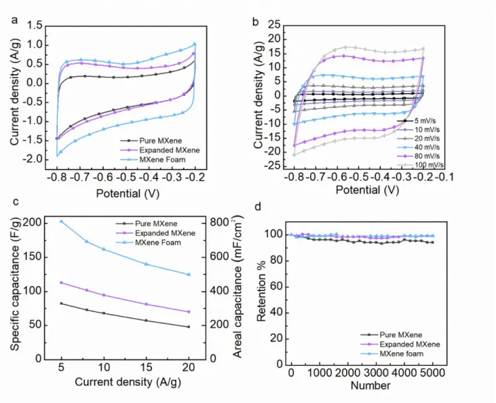
Figure 5. Electrochemical characteristics of binder-free electrodes in three electrode configurations using 1 M KOH as
electrolyte. (a) Comparison of CV curves of the prepared materials at 5 mV s-1 scan rate. (b) CV curves of MXene
foam electrode at various scan rates. (c) Comparison of the specific capacitances of the prepared material as a function of the applied current densities. (d) Comparison of the capacity retention of pristine MXene, expanded MXene and MXene foam at 5 A g-1 over 5000 charge-discharge cycles. Dashed curve for MXene Foam corresponds to data
Electrochemical performance of prepared electrode materials was investigated in three electrode configuration in 1M KOH electrolyte. In Figure 5a, the roughly rectangular shape of CVs at 5 mV s-1
demonstrates the pseudocapacitive behavior of prepared MXene-based materials. A similar behavior was also observed in 1M Na2SO4 neutral electrolyte while in acetonitrile organic electrolyte, the
electrochemical activity was limited (Figure S7). As demonstrated by the CVs of the MXene foam–based electrode in Fig. 5b, this behavior remains at higher scan rate, up to 100 mV s-1 at least, as only slight
distortions are observed. In the series, a quick comparison of the corresponding integral area at 5 mV s-1
scan rate suggests that the MXene foam -based electrode presents the greatest capacitance. This was confirmed by the galvanostatic charge-discharge measurements at 5 A g-1 (Fig. S8a) used for specific
capacitance calculations. The specific capacitance of pristine MXene is the lowest at 80 F g-1. For
expanded MXene, capacitances is 112 F g-1. Finally, the greatest specific capacitance at 5 A g-1 was
measured at 203 F g-1 (811 mF cm-2) for the MXene foam –based electrode. This enhancement can
certainly be assigned to the progressive opening of the material structures in the series leading to a larger electrochemical interface and greater number of sites available for electrolytic ions involved in charge compensation. The improvement in the ion transport capabilities of the materials is also confirmed by the specific capacitance retention at higher scan rate (Fig. 5b). In addition, the achieved capacitance of MXene foam in this paper exceeds other MXene-based supercapacitors. For instance, Zhao et al.57
prepared a composite, in which RGO plays a role of conductive “bridge” to link with Ti3C2Tx blocks, thus
showing a specific capacitance of 154 F g-1 at 2 A g-1. Zhu and co-workers58 decorated the TiO
2 on the
Ti3C2 layers by using a simple in situ hydrolysis and heat-treatment process. The synthesized composite
revealed a high specific capacitance of 143 F g-1 at 5 mV s-1. Yang et al.59 deposited the binder-free Ti
3C2
MXene/carbon nanotubes films onto graphite paper by the electrophoretic deposition method. The as-prepared electrode displayed 134 F g-1 at 1 A g-1. Shi et al.60 synthesized the MXene foam by using a
thermal treatment method to restrain the restacking issue. The obtained MXene foam exhibited a high capacitance of 123 F g-1 at 5 mV s-1. Starting with pristine MXene electrode at 48 F g-1, specific
capacitances at 20 A g-1 ranked about the same as the Expanded MXene electrode shows 70 F g-1 and
MXene Foam a remarkable 125 F g-1 specific capacitances (Fig. 5c and Fig. S8b). Moreover, the observed
actually shared by many MXene-based electrode materials.61, 62, 63, 64 Although a poor 65 % Coulombic
efficiency was measured for the MXene foam electrode at low current density (5 Ag-1), it reached up to
90% at 20 A.g-1. For pure MXene and Expanded MXene -based electrodes, fair Coulombic efficiencies of
99 and 95 % were measured, respectively. These values actually fit within the values reported in the literature with, in average, 81 % Coulombic efficiency when titanium carbide MXene is the active material in such pseudocapacitive electrodes (Table S2). Moreover, Coulombic efficiencies as low as 60 % were reported for an electrode based on a Ti2CTx/carbon nanotube film65. In the present study, limitations in
Coulombic efficiencies are assigned to parasitic redox reactions, more specifically those involving the electrolyte, such as water reduction, and/or the MXene surface groups. The Faradaic origin of this (slow) phenomenon is supported by the improvement of the measured Coulombic efficiency as the scan rate (or current density) is increased (Fig. S9a). The detrimental effects of such parasitic Faradaic reactions are obviously related to the developed active surface area of the corresponding electrode material. As such they are progressively more marked for the electrode based on pure MXene, then expanded MXene, and finally MXene foam. Calculated Coulombic efficiencies were normalized by the active surface area of each electrode and plotted as a function of the applied current density (Fig. S9b). For all the electrodes in the series, the behavior of the normalized Coulombic efficiency is the same when increasing the applied current density, confirming the dependence of the Coulombic efficiency towards the electroactive surface area and the unique Faradaic origin of the parasitic reaction impeding the electrode Coulombic efficiencies. By the end, the improvement of the Coulombic efficiency with charge/discharge rate makes these materials as remarkably suited for supercapacitor application, especially when using an MXene foam -based electrode for which the improvement is the greatest. A more detailed analysis was done on the kinetics of the charge storage in the various prepared MXene-based electrode materials. First, the Log-Log current versus scan rate curves were plotted from CV data at various scan rates (Fig. S10). b slopes were calculated at 1.06 (pure MXene), 0.99 (Expanded MXene) and 1.02 (MXene foam) and correspond to
i=a v
b relationship66, 67, 68. Being close to 1, they suggest the charge storage mechanism inthe corresponding materials to mostly proceed through fast surface-controlled processes, hardly limited by diffusion of electrolytic ions in the electrode bulk. Second, the stronger contribution of the surface material was especially confirmed for the MXene foam electrode by separating capacitive (surface) versus
diffusion-limited currents in the corresponding CVs operated at various scan rates (Fig. S11). The corresponding capacitive ratio are reported as an histogram in Fig. S12. It should be noticed that it is 71% at 5 mV s-1, implying a significant capacitive/surface contribution to the overall measured capacitance,
even at such a low scan rate. Furthermore, the capacitive contribution increases while raising the scan rate, suggesting that, at high rates, MXene foam stores charges mostly through surface reactions in the EDL.
Nyquist plots shown in Fig. S13 confirm the similar behaviour of the prepared electrodes at high frequency, especially in terms of charge transfer resistance, but the straight and sharp increase of the imaginary part of the impedance (-Z’’) of the MF -based electrode in the low frequency range confirms this material attractive capacitive performance. On the other hand, the cycle stability was tested for 5000 cycles by galvanostatic charge-discharge measurements at 5 A g-1 current density. The results are shown
in Fig. 5d for MXene–based electrodes. Dashed curve, especially between cycles #2000 and #3000, corresponds to data withdrawn because of equipment failure. Finally, the pristine MXene keeps 94 % of its initial specific capacitance, while expanded MXene and MXene foam show excellent 99 % capacitance retention.
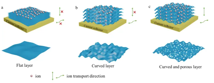
The electrochemical performances of the prepared electrode materials can be rationalized by using Gogotsi statement on the various strategies to prevent nanosheet re-stacking to fully use the developed surface area and enhance the electrolytic ion diffusion and transport.15 As shown in Figure 6a, the flat
layers of the pristine MXene are the less favorable material design in the series as nothing, in such a case, can prevent the natural trend of the layers to self-assemble in a re-stacked structure. The diffusion of the electrolytic ions is hindered by the limited inter-layer space and most of the electrochemically active surface corresponds to the external surface of the material. Ion diffusion perpendicular to the layer surface is only possible along the edges of the MXene particle. As such, corresponding electrochemical performances, especially specific capacitance and rate capability, are fair but also leave many room for improvement. In contrast, the morphology of the expanded MXene is inherited by the shape and the size of the MgO particles used as hard template. The open structure is promoted by the assembling of a composite made of exfoliated MXene layers wrapping MgO particles. After hard template removal in mild acidic conditions, its footprint remains, providing the assembled layers with a crumpled morphology and an enlarged interlayer space. The porosity generated in between the curved layers is obviously more favorable for in-plane fast ion transport and access to more active sites. As a consequence, both electrochemically active surface area and ion diffusion are greatly improved. So are the corresponding electrochemical performances. Unfortunately, diffusion through the plane is still limited to particle edges. This limitation can be overpassed by introducing porosity on the layers. The thermal decomposition of urea between or at MXene layers generate holes and promote a structure built on the assembly of curved porous layers. The resulting electrochemical performances of the prepared foam take advantage of this complexe 3D structure showing simultaneously large interlayer spaces and many connexions through the layers facilitating access of the electrolytic ions to the entire volume of the electrode.
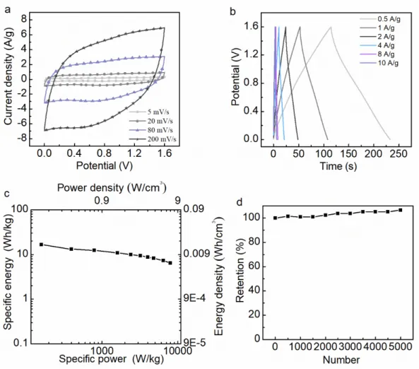
Figure 7. The electrochemical characteristic of symmetric MF//MF device. (a) CV curves at various scan rates. (b)
Cycling performance over 8k cycles of charge discharge at 5 A g-1.
The electrochemical performance of a symmetric device based on MXene foam –based electrodes (MF//MF) are shown in Figure 7 and Fig. S15. The CV curves in KOH 1M at various scan rates are displayed in Fig. 7(a).A decent device rate capability is anticipated since, up to 300 mV s-1, distortions of
the rectangular CV shape measured at low scan rate are very limited. Specific capacitance values were calculated from galvanostatic charging-discharging measurements at various current densities. Up to 20 A g-1 the signal kept the expected triangular shape with limited Ohmic drop (Fig. S15a). Device energy and
power densities were obtained from these measurements and reported in the Ragone plot shown in Fig. S15b. With electrode loadings at about 3.5 mg cm-2, the energy density of symmetric MF//MF device is
about 3.6 Wh kg-1 at 350 W kg-1 of power density. When relative to the cumulative volume of MF in both
electrodes, it translates as 2.5 Wh L-1 at 2.5 kW L-1. Although these performances are limited, the aim of
these measurements, either in 3- and 2- electrode setups, is to highlight the specific behavior of MF electrode, notwithstanding the potential limitations by any other “counter” electrode material. The cycle stability of device was measured at 5 A.g-1 over 8000 charge-discharge cycles. The calculated 87 %
capacitance retention confirm the fair stability of the electrode materials when operated in the given conditions (Fig. 7b). However, despite the promising electrochemical behavior of the electrode material, in such MF//MF symmetric device, the operating voltage is limited to 0.7 V with a severe impact on the
available energy density, especially. To address this issue, an asymmetric device was considered. It was built on a MnO2 positive electrode (Fig. S16) and a MF negative electrode. Electrochemical results in KOH
1M are summarized in Figure 8. In comparison with the symmetric MF//MF device, MF//MnO2 shows a
great enhancement as a 1.6 V cell voltage was obtained. Both CV and galvanostatic series of curves are characteristic of the pseudocapacitive behavior of the electrode components but the signal distortions are characteristic of lower rate capabilities (Fig. 8a and 8b). This was confirmed when calculating the device power density at 160 W Kg-1 or 8.5 kW L-1. In contrast the effect of the larger cell voltage is expressed by
an enhanced energy density at 16.5 Wh kg-1, 2 to 3 times greater than that of a C//C symmetric device
based on activated carbon electrodes in aqueous electrolyte69. When considering the volume of active
materials in both electrode, the volumetric energy density reached 10 Wh L-1 (4 times greater than that of
a C//C device). During the first 5000 charge-discharge cycles, the device capacitance progressively increased to reach more than 110% of the initial value at 25 F g-1 (Fig. 8d). This increase can be assigned
Figure 8. The electrochemical performance of asymmetric MF//MnO2 device. (a) CV curves at various scan rates. (b)
Galvanostatic charge-discharge test at various current densities. (c) Charge-discharge cycling performance at 5 A g-1
over 5k cycles.
Conclusion
To address the re-stacking issue of exfoliated MXene layers, we successfully prepared and engineered the expanded MXene and MXene foam materials by a hard template approach and a pore-forming method, respectively. As electrode materials, the binder-free MXene-based materials showed promising electrochemical performances in KOH 1M, either in terms of specific capacitance, rate capability and long term cycling. When moving from MXene to expanded MXene and MXene foam, the observed great improvement was assigned to the increase of the developed electroactive area and ion transport capability promoted by the morphology opening with larger interlayer space and pores through the MXene layers.
MF was tested as electrode material in devices. Both symmetric MF//MF and asymmetric MF//MnO2
devices displayed attractive rate capability and excellent cycle stability. Moreover, MF//MnO2 device
exhibited a fair energy density of 16.5 Wh kg-1and 10 Wh L-1. Acknowledgements
Y. C. ZHU (NO. 201606240097) is supported by China Scholarship Council (CSC). We thank C. Bodin and P. Lannelongue for help with the electrode preparation.
Reference
1. Novoselov, K. S. Mishchenko, A. Carvalho, A. Castro Neto, A. H., Science 2016, 353 (6298), aac9439. 2. Lin, D. Liu, Y. Liang, Z. Lee, H. W. Sun, J. Wang, H. Yan, K. Xie, J. Cui, Y., Nat Nanotechnol 2016, 11 (7), 626-32.
3. N. Jabeen, A. Hussain, Q. Xia, S. Sun, J. Zhu, and H. Xia, Adv. Mater. 2017, 29, 1700804. 4. Y, Zhao, W, Ran, et al. D. Gao and F. Gao, Small 2015, 11, 1310–1319.
5. Y. Zhao, et al., W, Huang, and T, Zhang, Adv. Energy Mater. 2017, 7, 1700005.
6. Lv, R. Robinson, J. A. Schaak, R. E. Sun, D. Sun, Y. Mallouk, T. E. Terrones and M. Terrones, Acc. Chem. Res. 2015, 48 (1), 56-64.
7. S. Karunakaran, et al., B. Basu, and M. De, J. Am. Chem. Soc. 2018, 140, 12634−12644.
8. Alhabeb, M. Maleski, K. Anasori, B. Lelyukh, P. Clark, L. Sin, S. Gogotsi, Y., Chemistry of Materials 2017, 29 (18), 7633-7644.
9. C. Zhang, et al., Y. Gogotsi, and V. Nicolosi, Stamping of Flexible, Adv. Funct. Mater. 2018, 28, 1705506.
10. Ling, Zheng, et al., Proceedings of the National Academy of Sciences 111.47 (2014): 16676-16681. 11. Gupta, A. Sakthivel, T. Seal, S., Progress in Materials Science 2015, 73, 44-126.
12. Yang, Xiaowei, et al. science 341.6145 (2013): 534-537.
13. Coleman, Jonathan N., et al. Science 331.6017 (2011): 568-571. 14. Augustyn, Veronica, et al. Nature Materials 12.6 (2013): 518.
16. Mas-Balleste, R. Gomez-Navarro, C. Gomez-Herrero, J. Zamora, F., Nanoscale 2011, 3 (1), 20-30. 17. Parvez, K. Wu, et al., R. Feng, X. Mullen, K., J Am Chem Soc 2014, 136 (16), 6083-91.
18. Lukatskaya, M. R. Mashtalir, O. Ren, C. E. Dall’Agnese, Y. Rozier, P. Taberna, P. L. Naguib, M. Simon, P. Barsoum, M. W. Gogotsi, Y., Science 2013, 341 (6153), 1502.
19. Wu, J. Zhang, Q. e. Wang, J. Huang, X. Bai, H., Energy & Environmental Science 2018.
20. W. Quan, C. Jiang, S. Wang, Y. Li, Z. Zhang, Z. Tang, and F. Favier, Electrochimica Acta, 2017, 247, 1072-1079.
21. Liu, Y. Lin, D. Liang, Z. Zhao, J. Yan, K. Cui, Y., Nat Commun 2016, 7, 10992. 22. Wang, Y. Song, Y. Xia, Y., Chem Soc Rev 2016, 45 (21), 5925-5950.
23. Yang, P. Sun, P. Mai, W., Materials Today 2016, 19 (7), 394-402.
24. Sun, Yiqing, Qiong Wu, and Gaoquan Shi. Energy & Environmental Science 4.4 (2011): 1113-1132. 25. Huang, Yi, Jiajie Liang, and Yongsheng Chen. Small 8.12 (2012): 1805-1834.
26. Stoller, Meryl D., et al. Nano letters 8.10 (2008): 3498-3502. 27. Hu, Liangbing, et al. ACS nano 5.11 (2011): 8904-8913.
28. Liu, Jinping, et al. Advanced Materials 23.18 (2011): 2076-2081. 29. Zhang, Xiong, et al. Electrochimica Acta 89 (2013): 523-529.
30. Zhang, Fan, et al. Energy & Environmental Science 6.5 (2013): 1623-1632. 31. Dubal, Deepak P., et al. Chemical Society Reviews 44.7 (2015): 1777-1790.
32. Wang, Yonggang, Yanfang Song, and Yongyao Xia. Chemical Society Reviews 45.21 (2016): 5925-5950.
33. Augustyn, Veronica, Patrice Simon, and Bruce Dunn. Energy & Environmental Science 7.5 (2014): 1597-1614.
34. Ding, L. Wei, Y. Li, L. Zhang, T. Wang, H. Xue, J. Ding, L. X. Wang, S. Caro, J. Gogotsi, Y., Nat Commun 2018, 9 (1), 155.
35. Lukatskaya, M. R. Kota, S. Lin, Z. Zhao, M.-Q. Shpigel, N. Levi, M. D. Halim, J. Taberna, P.-L. Barsoum, M. W. Simon, P. Gogotsi, Y., Nature Energy 2017, 2 (8), 17105.
37. Li, H. Hou, Y. Wang, F. Lohe, M. R. Zhuang, X. Niu, L. Feng, X., Advanced Energy Materials 2017, 7 (4), 1601847.
38. Tian, Y. Yang, C. Que, W. He, Y. Liu, X. Luo, Y. Yin, X. Kong, L. B., Journal of Power Sources 2017, 369, 78-86.
39. Yan, J. Ren, C. E. Maleski, K. Hatter, C. B. Anasori, B. Urbankowski, P. Sarycheva, A. Gogotsi, Y., Advanced Functional Materials 20, 27 (30), 1701264.
40. Yang, Q. Xu, Z. Fang, B. Huang, T. Cai, S. Chen, H. Liu, Y. Gopalsamy, K. Gao, W. Gao, C., J. Mater. Chem. A 2017, 5 (42), 22113-22119.
41. Ahmed, B. Anjum, D. H. Hedhili, M. N. Gogotsi, Y. Alshareef, H. N., Nanoscale 2016, 8 (14), 7580-7. 42. Chaudhari, N. K. Jin, H. Kim, B. San Baek, D. Joo, S. H. Lee, K., Journal of Materials Chemistry A 2017, 5 (47), 24564-24579.
43. Couly, C. Alhabeb, M. Van Aken, K. L. Kurra, N. Gomes, L. Navarro-Suárez, A. M. Anasori, B. Alshareef, H. N. Gogotsi, Y., Advanced Electronic Materials 2018, 4 (1), 1700339.
44. Sang, X. Xie, Y. Lin, M. W. Alhabeb, M. Van Aken, K. L. Gogotsi, Y. Kent, P. R. Xiao, K. Unocic, R. R., ACS Nano 2016.
45. Shahzad, F. Alhabeb, M. Hatter, C. B. Anasori, B. Man Hong, S. Koo, C. M. Gogotsi, Y., Science 2016, 353 (6304), 1137.
46. X. He, R. Li, et al., M. Zheng, Carbon, 2012, 50, 4911-4921.
47. Y. Zhang, et al., M. Xie and X. Guo, J. Mater. Chem. A, 2018, 6, 2353-2359.
48. J. Wei, D. Zhou, et al., Y. Xia and D. Zhao, Advanced Functional Materials, 2013, 23, 2322-2328. 49. Y.Cong, J. Zhang, F. Chen and M. Anpo, J. Phys. Chem. C 2007, 111, 19, 6976-6982.
50. C. Yang, W. Que, et al., Y. Yang and M. Que, Electrochimica Acta, 2017, 225: 416-424. 51. D. Qu, M. Zheng, et al., Z. Xie and Z. Sun, Nanoscale, 2013, 5, 12272-12277.
52. D. Qu, M. Zheng, et al., H. Fan and Z. Sun, Scientific reports, 2014, 4: 5294.
53. Z. Gordon W. Liu, M. Liu and C. Wong, Advanced Energy Materials, 2012, 2, 884-888.
54. L. Sun, et al., M. Li and H. Fu, RSC Adv., 2012, 2, 4498-4506.
55. W. Bao, et al., D. Wang and G. Wang, Advanced Energy Materials, 2018, 8(13): 1702485. 56. Li, L. Zhang, M. Zhang, X. Zhang, Z., Journal of Power Sources 2017, 364, 234-241.
57. C. J. Zhao, et al., ACS Appl. Mater. Interfaces 2016, 8, 15661−15667.
58. J. F. Zhu, et al., Journal of The Electrochemical Society, 2016, 163 (5) A785-A791.
59. L. Yang, W. Zheng, P. Zhang et al., Journal of Electroanalytical Chemistry 2018, 1-6, 830-831. 60. L. Shi, S. Lin, W. Wu, et al., Ceramics International 44 (2018) 13901–13907.
61 J. Jian, X. T. Yuan, et al., J. H. Lin and J. L. Sun, Advanced Energy Materials, 2017, 7(15): 1602725. 62. X. Q. Xie, M. Q. Zhao, et al., G. X. Wang and Y. Gogotsi, Nano Energy, 2016, 26: 513-523.
63. Y. Yue, N. S. Liu, et al., J. Su and Y. H. Gao, ACS nano, 2018, 12(5): 4224-4232.
64. C. F. Zhang, et al., Y. Gogotsi and V. Nicolosi, Advanced Functional Materials, 2018, 28(9): 1705506. 65. L. Li, F. Wang, J. Zhu and W. Wu, Dalton Trans., The facile synthesis of layered Ti2C MXene/carbon nanotube composite paper with enhanced electrochemical properties, 2017, 46, 14880.
66. C.-H. Lai, D. Ashby, M. Moz, Y. Gogotsi, L. Pilon, and B. Dunn Langmuir 2017 33 (37), 9407-9415. 67. P. Yu, C. Li, and X. Guo, The Journal of Physical Chemistry C 2014 118 (20), 10616-10624. 68. S.Y. Dong, et al., Q. Sheng and X.G. Zhang, J. Mater. Chem. A, 2015,3, 21277-21283