HAL Id: hal-01021569
https://hal-enac.archives-ouvertes.fr/hal-01021569
Submitted on 25 Sep 2014
HAL is a multi-disciplinary open access
archive for the deposit and dissemination of
sci-entific research documents, whether they are
pub-lished or not. The documents may come from
teaching and research institutions in France or
abroad, or from public or private research centers.
L’archive ouverte pluridisciplinaire HAL, est
destinée au dépôt et à la diffusion de documents
scientifiques de niveau recherche, publiés ou non,
émanant des établissements d’enseignement et de
recherche français ou étrangers, des laboratoires
publics ou privés.
Origin and avoidance of spurious solutions in the
transverse resonance method
Hervé Aubert, Bernard Souny, Henri Baudrand
To cite this version:
Hervé Aubert, Bernard Souny, Henri Baudrand. Origin and avoidance of spurious solutions in the
transverse resonance method. IEEE Transactions on Microwave Theory and Techniques, Institute of
Electrical and Electronics Engineers, 1993, 41 (3), pp 450-456. �10.1109/22.223744�. �hal-01021569�
450 IEEE TRANSACTIONS ON MICROWAVE THEORY AND TECHNIQUES, VOL. 41, NO. 3, MARCH 1993
Origin and Avoidance of Spurious Solutions
in the Transverse Resonance Method
H e n 6 Aubert, Bernard Souny, and Henri Baudrand,
Senior Member, ZEEEAbstract- In the context of transverse resonance method, a criterion is established for the choice of trial functions introduced in Galerkin’s method: this criterion allows to avoid the appear- ance of spurious solutions in the whole region of a propagation diagram and guarantees, at the same time, a good precision for the true solutions.
I. INTRODUCTION
OST OF the research dealing with the problem of
M
spurious solutions has been developed in the context of finite-element method and many options for avoiding these nonphysical solutions have been presented in scientific liter- ature [ 11-[4]: the fundamental cause of spurious modes lies in the inaccurate approximation of the zero eigenvalue and the corresponding eigenfunctions [ 5 ] . The enforcement of the divergence-free constraint on the trial functions allows to suppress spurious solutions present in the initial formulation VI, [61.Up to now, no scientific communication, at least to our knowledge, has dealt with the origin and the avoidance of spurious solutions in the transverse resonance method. This method, particularly well-adapted to the study of multilay- ered structures, is used very often to characterize dispersion phenomena in planar transmission lines [7]-[ 131: the size of matrices resulting from the transverse resonance condition is reduced considerably compared with the usual finite-element method. Meanwhile, spurious solutions may be encountered in the numerical treatment of the transverse resonance method which are difficult to distinguish from the true propagation constants and which hinder the systematic investigation of physical solutions: the origin of these embarassing solutions is very obscure and therefore their avoidance a priori seems to be quite difficult.
In this paper, the problem of spurious solutions is studied in the context of the transverse resonance method. We show that the characterization of dispersion phenomena in planar transmission lines gives rise to a resonance condition which has theoretically a solution for an infinite propagation constant. This nonphysical solution seems to be the origin of spurious solutions in the numerical resolution of dispersion problem: as a matter of fact, we show that the basic cause of spuri-
Manuscript received December 11, 1991; revised July 7, 1992.
H. Aubert and H. Baudrand are with Ecole Nationale Superieure d’Electrotechnique, d’Electronique, d’Informatique et d’Hydraulique de Toulouse, 2 rue Charles Camichel, 31071 Toulouse, France.
B. Souny is with Ecole Nationale de I’Aviation Civile, Avenue Edouard Belin, 31 Toulouse. France.
IEEE Log Number 9205463.
ous modes lies in the inaccurate approximation of the field belonging to this infinite-p solution.
In order to describe well the fields belonging to the infinite- @ solution, a criterion for the choice of trial functions used in the Galerkin’s method is rigorously found. In the E-field formulation, the tangential components of the electric field in the discontinuity plane are expanded over trial functions: the key step for the elimination of spurious solutions is the enforcement of zero curl of the E-field along the axis normal to the discontinuity plane. A similar criterion can be established in the H-field formulation, where we have to force the curl of the magnetic field to zero along the axis normal to the discontinuity plane.
The numerical applications of our general theoretical study is divided in two parts. First, in the case of unilateral finline, we consider the behavior of spurious and physical solutions with respect to the number of trial functions which do not satisfy the criterion deduced in the theoretical approach. These results illustrate the existence of an infinite solution for the propagation constant: the inaccurate description of the field belonging to this nonphysical solution generates spurious solutions.
In the second part of the numerical application, we show that a appropriate choice of trial functions satisfying the above mentioned criterion suppresses the spurious solutions and guarantees, at the same time, a good precision for the physical solutions.
11. THEORETICAL APPROACH
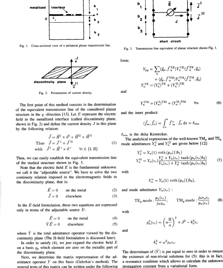
In order to illustrate the theoretical developments, consider the general unilateral transmission line of Fig. 1. The metal on the interface is distributed arbitrarily.
The dielectric substrate of Fig. 1 is assumed to be isotropic and homogeneous. Losses in the dielectric and in the conduc- tors as well as the metal thickness are neglected.
A. Transverse Resonance Method
The analysis of planar structures using the transverse reso- nance method has been the subject of numerous publications [7]-[13]. In this study, the application of the method to the characterization of dispersion phenomena in the planar transmission line of Fig. 1 will be presented in a brief development. Note only that the operator formalism is used to reinforce the systematic character of this method: it is a concise and clear way to treat the well-known relationships be- tween the electromagnetic fields, deduced from the equivalent transmission line of the structure.
45 1
AUBERT et al.: ORIGIN AND AVOIDANCE OF SPURIOUS SOLUTIONS
Fig. 1.
F
i
t
I
I
l b 3
Cross-sectional view of a unilateral planar transmission line.
short circuit
4
-form:
t i
The first point of this method consists in the determination of the equivalent transmission line of the considered planar structure in the 1~ -direction [13]. Let E represent the electric field in the metallized interface (called discontinuity plane, shown in Fig. 2) and define the current density J in this plane by the following relation:
J'= @I
n"
+ @I1 2 1 1 Thusf =
J"
+
J'"
(1) with J'Z = xZ i
Vz E {I, 11) b*4
b I
3 I short circuitFig. 3 . Transmission line equivalent of planar structure shown Fig. 1.
Then, we can easily establish the equivalent transmission line of the studied structure shown in Fig. 3.
Note that the electric field E is the fundamental unknown: we call it the "adjustable source". We have to solve the two continuity relation imposed to the electromagnetic fields in the discontinuity plane, that is:
Y,'" = (Y,')'"
+
(Y,")'" V n and the inner product:Smn is the delta Kronecker.
mode admittances Y,' and Yil are given below [12]:
The analytical expressions of the well-known TM, and
TE,
Y,' = Yn(l) coth(pn(l)bi) discontinuity plane
Fig. 2. Presentation of current density. and
with
+
E = 0 on the metal (2) and mode admittance Yn(er) :
J ' = 0 elsewhere
(8)
(3) P n ( E r ) . J W E o E r
TE, mode :
-,
TM, mode :-
J W P O P n ( E r )
In the E-field formulation, these two equations are expressed only in terms of the adjustable source E: with
8
= 0 on the metal (4)Y8
= 0 elsewhere ( 5 )and where Y is the total admittance operator viewed by the dis- continuity plane (The H-field formulation is discussed later). on a basis g p which element are zero on the metallic part of the discontinuity plane.
Next, we determine the matrix representation of the ad- mittance operator Y on this basis (Galerkin's method). The general term of this matrix can be written under the following
In order to satisfy (4), we just expand the electric field E k,2 = w2p0t,.
The determinant of (Y) is put equal to zero ifi order to ensure the existence of non-trivial solutions for (5): this is in fact, a resonance condition which allows to calculate the unknown
452 IEEE TRANSACTIONS ON MICROWAVE THEORY AND TECHNIQUES, VOL. 41, NO. 3, MARCH 1993
B. Existence of an Infinite Solution for the Propagation Constantp
to the infinite-P solution, we have to choose trial functions
4,"(x)
and $ y ( x ) so that:(1 1)
By applying the transverse resonance method, we demon-
strate the existence of an infinite solution for the dispersion
4m(-yx
a4:
) (. vm problem. In other words, we demonstrate the fact that:with
( Y ) ( Z )
-0a
-mThe symbol ( Y ) defines the matrix representation of the
admittance 'perator On the basis g p and
p
denotes the LdCnown where e," ande y
are the components Over trial functions4:
propagation constant along the z-axis. We can write: and
4:
respectively.Comments: 1) In the H-field version of the method, the current density is taken as the fundamental unknown of the problem.
From (2) and (3), the new equations to be solved will be the followings:
(2)
= C . P i ? P Pand the boundary condition (5):
(Y)(E') = 0
*
CYp,.,
= 0 v p (9)9 ZJ'= 0 on the metal (13)
with Ypq given above by (6). Since J = 0 elsewhere (14)
+
Y,T" + cc a + c c
instead of (4) and (5) considered in the E-field version, in which 2 is the total impedance operator viewed by the dis- continuity plane. Thus, we have to solve the system equations: and
(Z)(J) = 0
*
z p q x q = 0 v p(4
=&a
(10)we can find a solution E , for (9) when
p
is infinite: it is sufficient to take: Y y + 0P -
03 Vn P with P and 1 with z p , = C($P> f:E)j+f:E>G,) n ( G p ,IT",
= 0 V n > Pthat is to say E , expanded over a TM, basis satisfies the boundary conditions for infinite
p.
Thus, we obtain the following result: infinite-P is a possible theoretical solution of the dispersion problem. This nonphysi- cal solution satisfies the fundamental boundary conditions (5) and is transverse magnetic along y-axis.
Therefore, we obtain a similar criterion of (1 1 ) for the choice of trial functions
e,m
and expanding the current density in the discontinuity we could easily demonstrate that aTE, condition must be satisfied in to fully describe all the mathematical solutions of (13) and (14). This condition can
be expressed in terms of the current density. In fact, we have: In other words, from the Maxwell equation, we can
(e
xE )
. y ' = - j w &. g =
0 ( e x x ) . g = j w t Z . ? j = Osince since
H , = 0 E, = 0
which leads to with
aE, dE, d z ax
= o
+ + J = H x @ dE.2 Therefore:ax
d J , a J , ax a z+
-jPE, =-
Therefore. in order to fullv described all the solution of the = 0 boundary problem, that is to say the electric field belonging to
AUBERT et al.: ORIGIN AND AVOIDANCE OF SPURIOUS SOLUTIONS 453
so the current density in the discontinuity plane must be expanded over trial functions 6: and which do satisfy the following relationship:
In this manner, in order to avoid the spurious solutions-or
at least, to numerically remove these solutions far away from the physical ones-it seems judicious to choose trial functions satisfying the criterion (11) in the E-field formulation or Note that the application of the criterion (1 1) and (15) does not depend on the structure configuration. As matter of fact, the criterion ( 1 1) (resp. (15)) is deduced from the zero TM, mode admittance (resp. zero TE, mode impedance) when @ is infinite: this property is quite general and, therefore, the criterion is applicable for all kinds of planar transmission lines.
80,-
e m . & 4
Qm (15) criterion (15) in the H-field formulation.(16) with
where 2: and z? are the components over trial functions 0: and 0," respectively.
Note that this result has been used for other reasons by Jansen in [18] for the characterization of dispersion phenom- ena in single and coupled microstrip lines.
2) An analogy can be made between our approach and
the one used in the finite-element method: the basic cause of spurious modes in the latter method lies in the inaccurate approximation of the zero eigenvalues and the corresponding eigenfunctions [ 5 ] . These spurious modes do not satisfy the free divergence Maxwell equation. Indeed, the equation to be solved is:
111. NUMERICAL RESULTS AND DISCUSSION
A . Numerical Properties of Detected Spurious Solutions
Let N , and N , represent the number of trial functions along
the
x
and z-axis respectively, being inevitably finite numbers for the numerical requirements. The values of these parameters are conditioned by the convergence criterion on the solution for the propagation constantp.
The analytical expression of trial functions is given in such a way to ensure a good accuracy of obtained results, to build a well-conditioned matrix and to calculate easily the matrix
(e
xe
xE )
- IC:,!? = 0 (17) elements [14].Usually, in order to reduce the matrix size, the edge effects,
In the case of isotropic and homogeneous media, by taking
the divergence of (17) we obtain:
that is to say the tendmcY of the mx-"m electric field compo- nent to a metallic edge to become infinite near this edge, are taken into account by the choice of appropriate trial functions Take the example of a unilateral finline: the metallization thickness is assumed to be zero and allows us to choose the following usual trial functions for the electric field in the slot:
(3
xG
x2)
- k i e . 2 = 0 1151.which gives
(18)
k ? G . E = O
So, (1 8) yields mathematically a non zero divergence of the
electric field when k , is equal to zero. The divergence of the eigenfunctions belonging to the zero eigenvalue is not zero.
The key step for the elimination of spurious modes is the enforcement of the zero divergence of the vector fields used for the fields description [2]-[6]. This static solution for w = 0 is obviously a uninteresting one, but must be mathematically well-described, otherwise it takes a finite value and may appear as spurious solution in the investigation domain of physical solutions.
In the context of transverse resonance method, we formu-
late an analogous principle: since infinite-/3 is a solution of the boundary equations to be solved, we have to describe simultaneously the E , field corresponding to this solution and the E field belonging to the physical solutions. In other words, we have to choose correct trial functions which have to be appropriate for taking into account the characteristics of the true solutions and the requirement for infinite- /3 solution. If this choice is not made, that is if the trial functions do not allow to describe the theoretical E , field, the infinite- @ solution will take a very embarassing finite value in the numerical treatment (becoming visible as a zero determinant in the domain of real solutions) and will hinder the investigation of physical solutions. 27r a cos ( m - 1)- (x -
1)
4,"(x)
= Q m E { l , 2 , 3 ; . . , N Z ) &(x) = sin ( k - wwhere w designates the slot width. Thus, one or two trial functions are enough to obtain good numerical results for the propagation constant [ 161.
But, with these acceptable solutions, we detect another solution, called ,Boo, which has a surprising behavior versus the number of trial functions.
As a matter of fact, for a given number of modes, there
exists a number N = N , = N , of trial functions beyond which this solution takes increasingly larger values (Fig. 4): The greater is the number N of trial functions, the better are described all the solutions of the boundary problem, especially the infinite-@ solution. Thus numerical solution
pm
is removed to infinity for a sufficiently large number of trial functions.The transverse Magnetic nature along the y-axis of the infinite-
p
solution can be illustrated by the calculation of the454 IEEE TRANSACTIONS ON MICROWAVE THEORY AND TECHNIQUES, VOL. 41, NO. 3, MARCH 1993 + 30modes * 40mOdes + 50mcdes * 60mcdes 70modes * 80modes --t Wmodes = physicalsduhn 0 0 5 10 I5
number Of Wel fUncli0Il.S N = NX = Nz
Fig. 4. The two numerical solutions of the resonance condition versus the number of trial functions in the case of a unilateral finline: a = 3 . 5 5 6 mm,
bl = 3 , 5 5 6 mm, = 0.254 mm, b3 = 3.302 mm, E,. = 2. 22 with a frequency of 30 GHz.
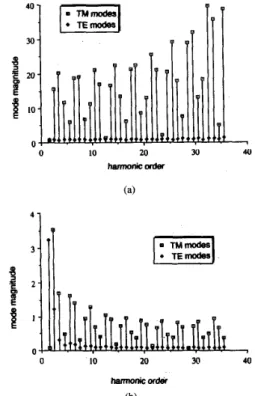
mode magnitudes of spurious solutions
p,:
take a very large value for solution of the resonance condition det ( Y ) = 0 and determine the true solution of this resonance condition. As an example, in the case of a unilateral finline, with 70 modes and 1 1 trial functions, we give the mode magnitude spectrum for these two kinds of solutions (Fig. 5). It can be noted that the solution is principally Transverse Magnetic, since the TE, mode magnitudes are negligeable compared with TM, mode magnitudes.B . Avoidance of Spurious Solutions z-axis mentioned above:
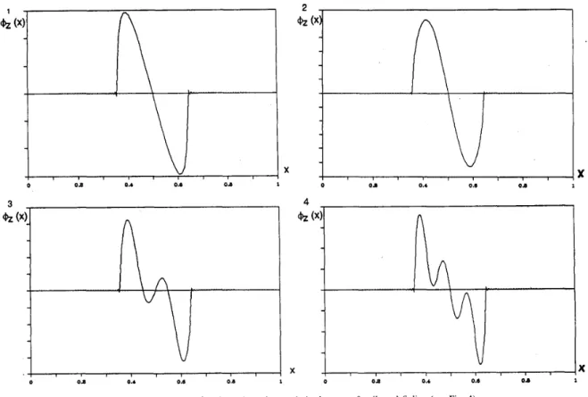
Applying the criterion (11) with the trial functions along
4Z(X) =
Vm E {l,2,3,...,Nz}
and
(20)
yields trial functions along z-axis which have not to be expressed analytically. Actually, the matrix representation of the admittance operator needs only the determination of the inner products
(4:,
f n z ) , since the other inner products(4pl
fnz) can be easily deduced by integration by part:Mk,
f n z ) =caz4,",
f n z )=
-k#t,
a z f n Z ) a ( d t , fnz)Therefore, we calculated twice less inner products in this case than in the case of classical trial functions given by (20).
A, is introduced in (20) to ensure a zero-component of the electric field on the fin (boundary condition).
Nevertheless, for information, we give the variation of the first trial functions along the z-axis in the discontinuity plane (Fig. 6).
The obtained results with the new kind of trial functions are very encouraging: the spurious solutions
Pm,
detected in30
3
g
202
t
lo 0 0 LO 20 w 4u harmonicorder 4 1P
d l n 0 10 20 a 40 harmonicor& (b)Fig. 5. Mode Magnitudes spectrum. (a) Of spurious solution: 0 = 61.240,01 rad/m. (b) Of physical solution: = 598,82 rad/m.
the calculation of the propagation constant of the fundamental mode in a unilateral finline, has disappeared, or at least, is removed far away from the investigation domain of physical solutions for
p
(its value is greater than lo8 rad/m !).The cosine trial functions, namely:
V m E { 1 , 2 1 3 , . . . , N z }
4:(z)
= sin(IC
- 1)- (z --
2w W
">
2V k E { 1 , 2 , 3 , . . . , N z } (21)
seem not to generate spurious solutions-moreover note that they satisfy the criterion (1 1)-and do not involve complex calculations. The drawback in the manipulation of this kind of trial functions is that the solutions of the resonance condition (zero determinant) do not converge very well with the number of these trial functions. Since they do not take the edge effects into account, they involve matrices of relatively large sizes.
The variation of the determinant versus the propagation constant /3 for the three kinds of trial functions (19), (20), and
(21) (Fig. 7) shows a very similar behavior of the determinant
in the cases of the trial functions (20) and the cosine trial functions.
Finally, calculate the power density of the true and spurious solution in the cross section of a unilateral finline (Fig. 8) (the spurious solution is obtained in the case of trial functions which do not satisfy the criterion (1 l), that is those of equation (19)).
AUBERT et a/.: ORIGIN AND AVOIDANCE OF SPURIOUS SOLUTIONS
/I
1
h
/ I
with mal funcnons (IS1 3 I 0 O d 0.4 0.6 0.0 0 X 0 0 1 0.4 0.6 O d 1 0 O d 0.4 0.6 01 1
Fig. 6. The new trial functions along the z-axis in the case of unilateral finline (see Fig. 4).
i
wnh mal funcnons (IS1
455
x
I
0 6000
B (radlm)
Fig. 7. Determinant versus the unknown 3 for three kinds of trial functions.
We find that the energy of the physical solution is principally localized between the fins. In contrast, the spurious solution localizes its energy near the fins and essentially, near the edges.
IV. CONCLUSION
A very promising and simple criterion about the choice of
trial functions in Galerkin's method has been theoretically found to suppress spurious modes present in the transverse resonance method. With a particular choice of trial functions, this method does not suffer from the appearance of nonphysical solutions in the numerical resolution of dispersion problem.
(b)
Fig. 8. Power density in the cross section of a unilateral finline. (a) For the physical solution ( 3 = 598.82 rad/m). (b) For the spurious solution ( 3 = 61.240.01 rad/m).
I/
I I I456 IEEE TRANSACTlONS ON MICROWAVE THEORY AND TECHNIQUES, VOL. 41, NO. 3, MARCH 1993
ACKNOWLEDGMENT [16] 0. Picon, J. Ackar, V. Fouad, and Hanna, “Scattering parameters of a step discontinuity in a suspended microstrip line,” Microwave and Optical Technology Letters, vol. no. 1, Sept. 1988.
[I71 R. E. Collin, Field Theory of Guided Waves. New York: Mac-Graw Hill, 1960.
1181 R. H. Jansen. “High-speed computation of single and coupled microstrip
To M. Chaubet (Centre National d’Etudes Spatiales) for his encouragement, and to M. Ahmadpanah and M. Ghomi for their advice in the writing of this paper.
REFERENCES
J. A. M. Svedin, “A numerically efficient finite-element formulation for the general waveguide problem without spurious modes,” IEEE Trans. Microwave Theory Tech., vol. 37, no. 11, pp. 1708-1715, Nov. 1989. K. Hayata, M. Koshiba, M. Egushi, and M. Suzuki, “Vectorial finite- element method without any spurious solutions for dielectric waveguid- ing problems using transverse magnetic-field component,” IEEE, vol. MTT-34, no. 11, pp. 1120-1124, Nov. 1986.
D. R. Lynch and K. D. Paulsen, “Origin of vector parasites in numerical Maxwell solutions,” IEEE Trans. Microwave Theory Tech., vol. 39, no. K. D. Paulsen and D. R. Lynch, “Elimination of vector parasites in finite element Maxwell solutions,” IEEE Trans. Microwave Theory Tech., vol. 39, no. 3, pp. 395-404, Mar. 1991.
I. Bardi and 0. Biro, “An efficient finite-element formulation without spurious modes for anisotropic waveguides,” IEEE Trans. Microwave Theory Tech., vol. 39, no. 7, pp. 1133-1139, July 1991.
K. Hayata, M. Eguchi, and M. Koshiba, “Finite element formulation for guided-wave problems using transversal electric field component,” IEEE Trans. Microwave Theory Tech., vol. 37, no. 1, pp. 256-258, Jan. 1989. R. Sorrentino and T. Itoh, “Transverse resonance analysis for finline discontinuities,” IEEE Trans. Microwave Theory Tech., vol. MTT-32, no. 12, pp. 1633-1638, Dec. 1984.
J. Bomemann and F. Amdt, “Calculating the characteristic impedance of finlines by transverse resonance method,” IEEE Trans. Microwave Theory Tech., vol. MTT-34, no. 1, pp. 85-92, Jan. 1986.
G. Schiavon, R. Sorrentino, and P. Tognolatti, “Characterization of coupled finlines by generalized transverse resonance method,” Inter- national Journal of Numerical Modelling: Electronic Networks. Devices and Fields, vol. 1, pp. 45-59, 1988.
G. Bartolucci and R. Sorrentino, “Equivalent circuit modeling of fin- line end-coupling and short-end by generalized transverse resonance analysis,” J . Electromagn. Waves Appl., vol. 2, no. 1, pp. 63-76, 1988. T. Uwano, R. Sorrentino, and T. Itoh, “Characterization of stripline crossing by transverse resonance analysis,” IEEE Trans. Microwave Theory Tech., vol. MTT-35, no. 12, pp. 1369-1376, Dec. 1987. T. Itoh Ed., Numerical Techniques for Microwaves and Millimeter- Waves Passive Structures. New York: Wiley-Interscience, ch. 11, 1989. H. Baudrand, “Representation by equivalent circuit of the integral methods in microwaves passive elements,” 20rh EuMc, Budapest, Sept. 1990.
R. F. Hamngton, Field Computation by Moment Method. New York: MacMillan, 1968.
R. Mittra and S . W. Lee, Analytical Techniques in the Theory of Guided Waves. New York: MacMillan, 1950.
3, pp. 383-394, Mar. 1991.
~~
parameters including dispersion, high-order modes, loss -and finite strip thickness,” IEEE Trans. Microwave Theory Tech., vol. MTT-26, no. 2,
pp. 75-82, Feb. 1978.
H e r d Aubert was bom in Toulouse on July 22, 1966. He received the “Diplome d’Ing6nieur” degree in electronics from the Institut National Polytechnique de Toulouse, France, in 1989.
Since then, he has been working on the electromagnetism model- ing in the “Groupe Microondes” of the “Ecole Nationale Supdrieure d’Electrotechnique, d’Electronique, d’tnformatique et d’Hydraulique de Toulouse (E.N.S.E.E.I.H.T), where he is presently studying towards “Docteur en Electronique” Degree.
Bernard Souny was bom in Ussel on November 20, 1950. He received the “Diplome d’Ing6nieur” degree in electronics from the Ecole Nationale de 1’Aviation Civile (ENAC), Toulouse, France, in 1973.
After four years passed in the Centre de Controle R6gional de la Navigation Aerienne, Bordeaux, France, he joined ENAC in 1978, where he works on Microwave Circuits and Electromagnetism.
Henri Baudrand (M’S&SM’90) was bom in France in 1939.He received the Diplome d’IngCnieur degree in electronics and the Docteur-bs-Science degree in microwaves, both from the Institut National Polytechnique of Toulouse, France, in 1962 and 1966, respectively.
Since then he has been working on the modeling of active and passive microwave circuit devices in the Electronics Laboratory of ENSEEIHT in Toulouse. Currently he is a Professor of Microwaves and is in charge of the Microwaves Research Group, and member of IEEE-MTT French Chapter.