Design of Real-time PID tracking controller using
Arduino Mega 2560for a permanent magnet DC
motor under real disturbances.
(1)ZARIFI AdelElectrical Engineering Department, Faculty of Sciences and Applied Sciences, University of Bouira, Algeria.
(10000) Bouira, Algeria adelzarifi10@gmail.com
(2)AIT ABBAS Hamou
line 2: Laboratoire d’informatique,
Mathématique et Physique pour l’agriculture et les Forets, Electrical Engineering Department,
Faculty of Sciences and Applied Sciences, university of Bouira, Algeria
(10000) Bouira, Algeria h.aitabbas@univ-bouira.dz
(3)SEGHIOUR Abdellatif Ecole Supérieure en Génie Electrique
et Energétique
Oran (31000), Algeria. seghiour.abdellatif@gmail.com
Abstract— The most widely used control strategy in industry is proportional integral derivative (PID) controller. The popularity of PID controllers can be attributed partly to their robust performance in a wide range of operating conditions and partly to their functional simplicity. One of the applications is to control CNC cutting machine model by using permanent magnet DC motor as actuator.
In the current work, we contribute to present the design of Real-time PID tracking controller using Arduino Mega 2560 for a permanent magnet DC using Matlab with the intention to both illustrate graphical interface properties using (Matlab GUI) and display the responses of DC motor controlled through PID in real time under real constraints and disturbances. Furthermore, we implement it to the selected Arduino by using S upport Package for Arduino Hardware in MATLAB.
The speed control implementation of permanent magnet DC motor based on Arduino mega 2560 and L298N H-Bridge as alimentation using PID control method has been validated by experiments on the physical system. Practical results are presented to demonstrate the effectiveness and advantage of the system control scheme in Matlab in real time. Performance analysis shows the effectiveness of the proposed control scheme in real time.
Keywords— DC Servo Motor, MATLAB, PID Controller, User Interface, Arduino Mega 2560, L298N H-Bridge.
I. INT RODUCT ION
Industrial systems with high-efficiency and great performance have taken more advantages of robot technology. The large number of control research and many control applications were presented during the last years, concentrated on control of robotic systems. Robot man ipulator fie ld is one o f the interested fie lds in industrial, educational and medica l applications [1]. Due to their advantages over other conventional motors, such as better speed and torque characteristics, better dynamic response, high efficiency, no need for e xcitation current, no noise operation and high weight to torque ratio, re lative ly lo w cost [2], pe rmanent magnet DC (PM DC) motors have started to be used in many applications inc luding wiper blades, heater, air conditioners and personal co mputer, in recent years [ 3]. It works in unpredictable, haza rd and inhospitable circu mstances which human cannot reach, such as, working in nuclear or che mica l reactors is very dangerous, while
when a robot instead hu man it involves no risk to human life [2].
In literature, various control methods are used to regulate the speed of a PMDC motor [1, 3]:
1. The PID controller.
2. Advanced controller (adaptive and improving). 3. Intelligent controller (fu zzy and neural) in which we find: a) Feed forward control, b) Direct inverse control (e xtracting inverse dynamics), c) Indirect adaptive control method based on NN identification, d ) d irect adaptive control with guarantied stability, e) Feedback linearization, f) Pred ictive control [1]. In the direct inverse control method, a MNN is trained by specialized back-propagation algorithm [6, 7].
This last method has attracted much attention in recent years because it is intuitive, and simple to be imp le mented [8, 9, 10, 11, 12]. Ho wever, the plant to be controlled may not have a unique or stable inverse, which is the drawback o f direct inverse dynamics method.
The aim o f this paper is to verify the performance of the PID control strategy (with Zighle r Nichols method) based on low cost hardware (Arduino) wh ich is proposed for the real time control of the MPDC motor as actuators in CNC cutting mach ine under unstructured disturbances since much literature said that PID controllers has have better stability and small overshoot [2].
This paper has two main contributions ; Firstly, we take to use Matlab to program the Arduino in order to both illustrate graphical interface properties using (Matlab GUI) and visualize the responses of PMDC motor controlled v ia PID controller under real constraints and disturbances in real time . Para meters of the PID controller are calculated v ia zighler-Nichols method.
Secondly, we describe a design of Real-time PID trac king controller on a very ine xpensive At mega 2560 microcontroller and L298N H-Bridge as alimentation under real constraints and disturbances, validated by experiments on the physical system.
The paper will be o rganized as fo llo ws : Section-II describes the PMDC motor model. Section-III describes the design of the practical test bench. Section-IV is focused on the open loop control of the PMDC motor. Then, the closed loop control using the PID is presented in the Section-V. Finally, the conclusion presented in Section VI c loses the paper.
II. PHYSICS- BASED MODEL OF A PMDC MOTOR
DC servo motors are most appropriate for vast range speed control and are there fo r many adjustable speed drives. For the present case study, the corresponding electric circuit o f the physics-based model of a PMDC motor is illustrated in Fig….
Fig. 1: Schematic representation of the PMDC motor […] The physical parameters of the DC motor are:
x J: Moment of inertia; x f: Friction coefficient; x Kt: Motor torque coefficient ;
x Ke: Electromotive force coefficient ;
x L: Armature inductance ; x R: Armature resistance ;
Putting K=Kt=Ke, the model of the PM DC motor fo r
controlling speed can be represented by the transfer function:
The canonical form can be e xp ressed as a product of two first order:
with :
in which :
x τ: is the constant of electromechanical time (all the greater as the inertia J is large).
x τe: is the constant of electrical t ime (resulting fro m
the electronic co mponents, in particula r the inductance).
After some simp lifications on the orders of magnitude, the PMDC motor can be regarded as product of two functions of the first order :
III. DESIGN OF THE PRACT ICAL TEST BENCH
The equipments used for this e xperiment (as shown in Fig. 2) are : Ardu ino Mega 2560, L298N H-Bridge, DC powe r supply, PMDC motor, encoder (sensor speed) and computer with Matlab software.
Fig. 2: Photograph of the used equipments.
Re mind that there are several co mputer software to progra m the Arduino such as Lab Vie w, At mel Studio and Matlab. In the current paper, we like ly involve the Arduino IDE since it is the most used. Thus, it is available on the officia l website for free download (www.arduino.cc).
In this area, we contribute to use Matlab to program the Arduino in order to both illustrate graphical interface properties using (Matlab GUI) and visualize the responses of PM DC motor controlled via PID controller in rea l time . However, to be able to progra m the Arduino via Matlab, you have to download the "support package for Arduino Hardware".
A. SOFT PART (Control’s Interface using Matlab GUI)
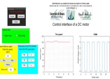
The PMDC motor control interface realized by Matlab GUI is illustrated in Fig. 3.
Fig. 3: The PMDC motor control interface designed with Matlab GUI
This control interface contains 4 blocks and 2 axes: the 4 blocks are:
1) Connec tion: which will allow us to confirm the connection / disconnection of the arduino with Matlab . 2) Contr ol’s kind: fro m which one will select the type of control that will be used (open loop or closed loop).
3) S pee d reference signal: in which we will designate the setpoint (the value of the refe rence signal) speed with which we will work.
4) Par ameters of the PID Controller: we introduce the gains of the regulator (Proportionel, Integral, De rivative) according to our need.
the 2 axes are:
1) the axis of the left is used to represent the speed response. 2) the right axis contains the PWM signal that was used. By installing this co mmand interface designed with Matlab GUI in a s martphone, it will g ive us the advantage of controlling our physical system (CNC mach ine based PMDC motor) remotely.
B. Hard PART (Control’s Interface using Matlab GUI)
Characteristics of the PMDC motor (type DCM2) used in this case study are[9] :
- 12 V motor with gearbox (1: 30 ratio)
- Power consumption: 530 mA approx. (and 150 mA empty) - Blocking current: 2.5 A
- Rotation speed: 170 rpm (216 rpm empty) - Torque: 1.5 kg.cm.
- Encoder: 360 pulses per revolution - Dimensions: Ø28.5 x 86.6 mm - Ø 5 mm shaft (4 mm on flat)
IV. OPEN LOOP CONT ROL OF THE PMDCMOT OR
A method of imp le menting the open loop control scheme is showed in Fig. 4.
Fig. 4: A PMDC motor speed control scheme In this case, we exp loit the designed PMDC motor control interface with Matlab GUI (see Fig. 5) and we proceed as follow:
Fig. 5: Parameters selection for open loop case on the PMDC motor Control interface.
a) we connect the used Arduino to Matlab in order to obtain confirmat ion in the first block (connecti on) of the designed control interface.
b) in the second block of the designed control interface (Control’s kind), we select “open loop”.
c) in the third bloc k (S pee d refere nce signal) of the control interface, we involve the value of the signal reference and we obtain the following practical results in real time:
A- without charge
Fig. 6: a) MPDC motor speed response with PID without resistant torque (set speed 100 rpm), b) PWM signal
B- With charge
Fig. 7: a) MPDC motor speed response with PID with resistant torque at t=4.8s (set speed 100 rp m), b) PWM signal
For the first case (without resistant torque), the Figure 6 illustrates the rotational speed and PWM waveforms. It is clear that the speed suitably follows the reference signal. Consequently, an exce llent tracking performance is reached which justifies the potential of the control system that has been realized.
For the second case, we start the PMDC motor without resistive torque, then we apply a load (resisting torque) at t = 4.8s, we notice that the speed decreases. It can be said that this control is not robust during the applicat ion of the load since the feedback does not intervene in open loop. The PWM signal re mains the same value when the load is applied (see Fig. 7 right).
V. CLOSE LOOP CONT ROL OF THE PMDCMOT OR
Fig. 8: A closed-loop PMDC motor speed control scheme based on PID controller.
The proportional-integral-derivative (PID) controllers a re e xtensively e xploited in industrial systems as they offer simp le configurat ion, are simp le to design and have low cost [3, 4]. The PID control is inserted in the direct chain of the servo-control, in series with the process, as indicated in Fig. 8. This regulator e laborates easily a control signal uc(p) by
combin ing the proportional (Kp), integral (Ki) and derivative
(Kd) terms acting on the error signal ε(t).
A. PID parameters according to the Ziegler-Nichols method
The PID para meters according to the Ziegler-Nichols of the PMDC motor are given in Table 1 [4].
Table 1: Parameter of a corrector according to Takahashi We choose the coefficients of the cor rectors P, PI and PID in the (Table 1) so-called coeffc ients of Takahachi, according to two methods of Ziegler and Nichols.
The first method of Ziegler and Nichols (the pumping method) is used to determine the Kp, Ki and Kd values. Fro m Table (1), we find the values of Kp = 0.36, Ki = 8 and Kd=0.125 .
B. Practical results in closed loop
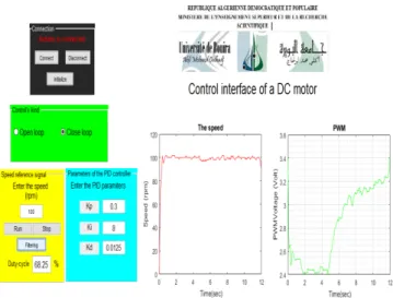
We also e xplo it the designed PMDC motor control interface (see Fig. 9) and we proceed as follow:
Fig. 9: Parameters selection for the closed loop case with PID controller on the PMDC motor Control interface. a) we connect the used Arduino Mega 2560 to Matlab in order to obtain confirmat ion in the first block (connecti on) of the designed control interface.
b) then, we select “closed loop” in the second block of the designed control interface (Control’s kind) .
c) after that, we involve the value of the signal refe rence (fo r e xa mple 100 rp m) in the third block (S pee d re ference
signal) of the control interface.
d) in the fourth block of the control interface, we introduce the values of the proposed controller (according to Zieg ler -Nichols method)
e)we return to the third block (Spee d reference signal) and we push the button “run”. Then, we obtain the following results:
A- Without charge
Fig. 10: a) MPDC motor speed response with PID without resistant torque (set speed 100 rpm), b) PWM signal
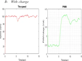
B- With charge
Fig. 11: a) MPDC motor speed response with PID with resistant torque (set speed 100 rpm), b) PWM signal
For the case without load and when starting the DC motor, the speed represents an acceptable overshoot and then it follows suitably the setpoint (100 rp m) with a satisfactory response time (see Fig. 10). As for the PWM, it peaks at (3.5 V) and then reaches the value (about 2.4 V, which imp lies α = 48%) for a speed reference equal to v = 100 rpm (see Fig. 11).
When the load is applied at the instant (t = 5s), the speed decreases and then immediately returns to its set point. For the PWM, it increases when the load is applied in order to compensate the real disturbance (Fig. 11).
Consequently, Experimental results of the PMDC motor controlled using PID controller demonstrate clearly the potential of the proposed control scheme in rea l time even with load torque variations . A video of the experiment can be senn at:
https://youtu.be/3yMMh2ohe-M
The presented work clearly argues about the powerful and the potential of the proposed control system in real time even under real constraints and disturbances . Furthermore, the presented practical results show that the PID controller can be an attractive solution for small devices based on low cost hardware such as Arduino.
VI. CONCLUSION
Better control performance, robustness and overall stability can be e xpected using the PID controlle r which has better stability, small overshoot, and fast response. Based on the results, the time response parameters can be observed. Even though, the PID controller produces the response with lower rise time.
Finally, the proposed experimental configuration offers an attractive experiment for undergraduate engineering students sinceboth we describe a design of Real-time PID tracking controller on a very inexpensive Atmega 2560 microcontroller and L298N H-Bridge as alimentation and we can remort ly control and visualise responses our physical system in real time under unstructured disturbances directely via the proposed control interface (designed with Matlab GUI).
REFERENCES
[1] Rai, N., & Rai, B. “Neural network based closed loop speed control of DC motor using arduino uno”. International Journal of Engineering T rends and T echnology, vol. 4, n. 2, pp. 137-140, 2013.
[2] Akbar, M. Amirullah. "Simulation of fuzzy logic control for DC servo motor using Arduino based on MATLAB/Simulink." Intelligent Autonomous Agents, Networks and Systems (INAGENT SYS), 2014 IEEE International Conference on. IEEE, 2014.
[3] Tir, Z., Malik, O., Cherif, H., Bekakra, Y., & Kadrine, A. “Implementation of a Fuzzy Logic Speed Controller For a Permanent Magnet DC Motor Using a Low-Cost Arduino Platform”, 5th international conference on Electrical Engineering-Boumerdes, Algeria, October 29-31, 2017.
[4] Hägglund, T., “PID controllers: theory, design, and tuning”, vol. 2. [5] Abbas, H. A., Zegnini, B., & Belkheiri, M. (2015, March). Neural
network-based adaptive control for induction motors. In Systems, Signals & Devices (SSD), 12th International Multi-Conference on (pp. 1-6). IEEE, 2015.
[6] Moussavi, S., Alasvandi, M., and Javadi, S. "Speed control of permanent magnet DC motor by using combination of adaptive controller and fuzzy controller,"International Journal of Computer Applications, vol. 52, pp. 11-15, 2012.
[7] Velagic, J., and Galijasevic, A. "Design of fuzzy logic control of permanent magnet DC motor under real constraints and disturbances," in 2009 IEEE Control Applications, (CCA) & Intelligent Control, (ISIC), pp. 461-466, 2009.
[8] Abbas, H. A., Belkheiri, M., & Zegnini, B. “Feedback linearisation control of an induction machine augmented by single-hidden layer neural networks”, International Journal of Control, 89(1), 140-155, 2016.
[9] Michel Pinard, “Commande électronique des moteurs électriques“, 2ème édition, paris, Dunod, (2004,2007).
[10] Ait abbas, H., Belkheiri, M., and Zegnini, B. “Robust Neural Output Feedback Tracking Control For a Class of Uncertain Nonlinear Systems Without Time-delay”, Nonlinear Dynamics and Systems T heory, (vol. 16, no. 02, pp. 115–128), 2016.
[11] Ait abbas, H., Belkheiri, M., and Zegnini, B. Radial Basis Function Neural Network-based Adaptive Control of Uncertain Nonlinear Systems, 3rd International Conference on Control, Engineering and Information Technology (CEIT’2015), Tlemcen-Algeria, (10.1109/CEIT.2015.7233124), 25-27 May, 2015.
[12] Belkheiri, M., Ait abbas, H., and Zegnini, B. Feedback Linearization Control of Nonlinear Uncertain Systems Using Single Hidden Layer Neural Networks, The 11th IEEE International Multi-Conference on Systems, Signals and Devices, (DOI: 10.1109/SSD.2014.6808779), Castelldefels-Barcelona, Spain, (11-14 Février 2014).