User-interactive wirelessly-communicating “smart” textiles
made from multimaterial fibers
Thèse
Stepan Gorgutsa
Doctorat en physique
Philosophiae doctor (Ph.D)
Québec, Canada
© Stepan Gorgutsa, 2016
User-interactive wirelessly-communicating “smart” textiles
made from multimaterial fibers
Thèse
Stepan Gorgutsa
Sous la direction de :
Prof. Younès Messaddeq, directeur de recherche
Prof. Sophie LaRochelle, co-directrice de recherche
Résumé
En raison de la nature intime des interactions homme-textiles (essentiellement, nous sommes entourés par les textiles 24/7 - soit sous la forme de vêtements que nous portons ou comme rembourrage dans nos voitures, maisons, bureaux, etc.), les textiles intelligents sont devenus des plates-formes de plus en plus attrayantes pour les réseaux de capteurs innovants biomédicaux, transducteurs, et des microprocesseurs dédiés à la surveillance continue de la santé. En même temps, l'approche commune dans le domaine des textiles intelligents consiste en l'adaptation de la microélectronique planaire classique à une sorte de substrat souple. Cela se traduit souvent par de mauvaises propriétés mécaniques et donc des compromis au niveau du confort et de l'acceptation des usagers, qui à leur tour peuvent probablement expliquer pourquoi ces solutions émergent rarement du laboratoire et, à l'exception de certains cas très spécifiques, ne soit pas utilisés dans la vie de tous les jours. Par ailleurs, nous assistons présentement à un changement de paradigme au niveau de l'informatique autonome classique vers le concept de calculs distribués (ou informatique en nuage). Dans ce cas, la puissance de calcul du nœud individuel ou d'un dispositif de textile intelligent est moins importante que la capacité de transmettre des données à l'Internet.
Dans ce travail, je propose une nouvelle approche basée sur l'intégration de polymère, verre et métal dans des structures de fibres miniaturisées afin de réaliser des dispositifs de textiles intelligents de prochaine génération avec des fonctionnalités de niveau supérieur (comme la communication sans fil, la reconnaissance tactile, les interconnexions électriques) tout en ayant une forme minimalement envahissante. Tout d'abord, j'étudie différents modèles d'antennes compatibles avec la géométrie des fibres et des techniques de fabrication. Ensuite, je démontre expérimentalement que ces antennes en fibres multi-matériaux peuvent être intégrées dans les textiles lors d’un processus standard de fabrication de textiles. Les tests effectués sur ces textiles ont montré que, pour les scénarios «sur-corps et hors-corps», les propriétés émissives en termes de perte de retour (S11), le patron (diagramme) de radiation, l'efficacité (gain), et le taux d'erreur binaire (TEB) sont directement comparables à des solutions classiques rigides. Ces antennes sont adéquates pour les communications à courte portée des applications de communications sans fil ayant un débit de données de Mo/s (méga-octets par seconde) (via protocoles Bluetooth et IEEE 802.15.4 à la fréquence de 2,4 GHz). Des simulations numériques de taux d'absorption spécifique démontrent également le plein respect des règles de sécurité imposées par Industrie Canada pour les réseaux sans fil à proximité du corps humain.
Puisque les matériaux composites de fibres métal-verre-polymère sont fabriqués en utilisant des fibres de silice creuses de diamètre submillimétrique et la technique de dépôt d'argent à l'état liquide, les éléments conducteurs sont protégés de l'environnement et ceci préserve aussi les propriétés mécaniques et esthétiques des vêtements. Cet aspect est confirmé par des essais correspondant aux normes de l'industrie du textile, l'étirement standard et des essais de flexion. De plus, appliquer des revêtements superhydrophobes (WCA = 152º, SA = 6º) permet une
communication sans fil sans interruption de ces textiles sous l'application directe de l'eau, même après plusieurs cycles de lavage.
Enfin, le prototype de textile intelligent fabriqué interagit avec l'utilisateur à travers un détecteur tactile et transmet les données tactiles à travers le protocole Bluetooth à un smartphone. Cette démonstration valide l’approche des fibres multi-matériaux pour une variété d'applications.
Abstract
As we are surrounded by textiles 24/7, either in the form of garments that we wear or as upholstery in our cars, homes, offices, etc., textiles are especially attractive platforms for arrays of innovative biomedical sensors, transducers, and microprocessors dedicated, among other applications, to continuous health monitoring. In the same time, the common approach in the field of smart textiles consists in adaptation of conventional planar microelectronics to some kind of flexible substrate, which often results in poor mechanical properties and thus compromises wearing comfort and complicates garment care, which results in low user acceptance. This explains why such solutions rarely emerge from the lab and, with the exception of some very specific cases, cannot be seen in the everyday life. Furthermore, we are currently witnessing a global shift from classical standalone computing to the concept of distributed computation (e.g. so-called thin clients and cloud storage). In this context, the computation power of the individual node or smart textile device in this case, becomes progressively less important than the ability to relay data to the Internet.
In this work, I propose a novel approach based on the idea of integration of polymer, glass and metal into miniaturized fiber structures in order to achieve next-generation smart textile devices with higher-level functionalities, such as wireless communication, touch recognition, electrical interconnects, with minimally-invasive attributes. First, I investigate different possible fiber-shaped antenna designs and fabrication techniques. Next, I experimentally demonstrate that such multi-material fiber antennas can be integrated into textiles during standard textile manufacturing process. Tests conducted on these textiles have shown that, for on-body and off-body scenarios, the emissive properties in terms of return loss (S11), radiation pattern, efficiency (gain), and bit-error rate (BER) are directly comparable to classic ‘rigid’ solutions and adequately address short-range wireless communications applications at Mbps data-rates (via Bluetooth and IEEE 802.15.4 protocols at 2.4 GHz frequency). Numerical simulations of the specific absorption rate (SAR) also demonstrate full compliance with safety regulations imposed by Industry Canada for wireless body area network devices.
Since metal-glass-polymer fiber composites were fabricated using sub-millimetre hollow-core silica fibers and liquid state silver deposition technique, the conductor elements are shielded against the environment and preserve the mechanical and cosmetic properties of the garments. This is confirmed by the textile industry standard stretching and bending tests. Additionally, applied superhydrophobic coatings (WCA=152º, SA=6º) allow uninterrupted wireless communication of the textiles under direct water application even after multiple washing cycles. Finally, I fabricated a user-interactive and wireless-communicating smart textile prototype, that interacts with the user through capacitive touch-sensing and relays the touch data through Bluetooth protocol to a smartphone. This demonstration validates that the proposed approach based on multi-material fibers is suitable for applications to sensor fabrics and bio-sensing textiles connected in real time to mobile communications infrastructures, suitable for a variety of health and life science applications.
Table of Contents
Résumé ... iii Abstract ... v Table of Contents ... vi List of Tables ... ix List of Figures ... xList of Abbreviations ... xiv
Acknowledgements ... xvi
Foreword ... xvii
Chapter 1 Introduction ... 1
1.1 Literature review ... 1
1.1.1 Early trends in smart textiles ... 1
1.1.2 Smart textile functionalities of today ... 2
1.1.3 Fiber-shaped electronics ... 5
1.1.4 Wireless communications – RF textile antennas ... 7
1.1.5 Summary ... 10
1.2 Multimaterial fibers – research opportunity for the next generation of smart textiles ... 11
1.3 Research objective and organization of the thesis ... 13
1.3.1 Research objective and strategy ... 13
1.3.2 Thesis structure ... 13
Chapter 2 Fiber antenna basics and fabrication ... 15
2.1 LCX antenna ... 15
2.2 Wire-shaped antennas ... 17
2.3 Fiber fabrication ... 19
2.3.2 Copper deposition ... 20
2.3.3 Effect of the surface roughness on the electrical properties of the Ag and Cu coatings ... 21
2.4 Textile integration ... 24
2.5 Summary ... 25
Chapter 3 Textile antenna characterization ... 26
3.1 Emissive properties ... 26 3.1.1 Return loss (S11) ... 26 3.1.2 Radiation pattern ... 29 3.1.3 Gain measurements ... 31 3.1.4 Impedance matching ... 32 3.1.5 On-body performance ... 34 3.2 Mechanical properties ... 36
3.2.1 Effects of mechanical stretching and bending ... 36
3.3 Environmental endurance ... 39
3.3.1 Effect of water on fiber antenna performance ... 39
3.3.2 Hydrophobic coating ... 40
3.3.3 Washing cycles ... 43
3.4 Safety (SAR) ... 44
3.4.1 SAR simulations ... 44
3.4.2 Power loss measurements ... 44
3.5 Conclusions ... 46
Chapter 4 Textile touch transmission link prototype ... 47
4.1 Data transmission with textile antennas ... 47
4.1.1 BER ... 47
4.1.2 Bluetooth ... 49
4.3 User-interactive textile with Bluetooth connectivity ... 52
4.4 Conclusions ... 54
Chapter 5 Conclusion and Perspectives ... 55
5.1 Conclusions ... 55
5.2 Perspectives ... 56
5.2.1 Respiration sensor ... 56
5.2.2 IR-UWB approach ... 57
References ... 58
Appendix A: Published Papers ... 65
"Novel Wireless-Communicating Textiles Made from Multi-Material and Minimally-Invasive Fibers" ... 66
"Emissive Properties of Wearable Wireless-Communicating Textiles Made From Multimaterial Fibers" ... 82
"User-Interactive and Wireless-Communicating RF Textiles" ... 91
"Washable hydrophobic smart textiles and multi-material fibers for wireless communication" ... 101
List of Tables
Table 1 Effective conductivity for deposited Cu and Ag films ... 23
Table 2 Dielectric properties of different tissues at 2.4 GHz. ... 34
Table 3 Frequency shift induced by the proximity to the phantom ... 35
Table 4 Hydrophobic properties of the multi-material fibers, materials and textiles in different configurations ... 42
List of Figures
Figure 1 (a) Woven electronic fibers with sensing (humidity, temperature) and display (LED) functions [31]. Copyright 2010, WILEY-VCH Verlag GmbH & Co. KGaA, Weinheim. (b) Design of the FBG sensor integrated into a harness (c) for respiratory monitoring [32] (d) Schematic of 3D stacked paper skin structure composed of pressure, temperature, and humidity arrays. (e) Digital photograph of flexible temperature sensors array [33] Copyright 2016, WILEY-VCH Verlag GmbH & Co. KGaA, Weinheim (f) Images of the stretchable graphene thermistors at relaxed and twisted states [34] Copyright 2015 American Chemical Society (g) Thermochromic ink [35] (h) Liquid crystal ink [36] Copyright 2006, ACM New York, NY, USA and (i) optical fiber based textile displays [37] Copyright 2016 Optical Society of America (j) prototype mechanical energy harvesting dress [38] (l) the piezoelectricity harvesting garment module [39] Copyright 2016 IOP Publishing Ltd (m) flexible, solid electrolyte lithium battery stripes integrated into textiles [40] Copyright 2012 The Electrochemical Society. ... 4
Figure 2 (a) Structure of the fiber-based supercapacitor [45] Copyright, 2014, WILEY-VCH Verlag GmbH & Co. KGaA, Weinheim (b) Schematic illustration of the fiber pressure sensor [48] Copyright, 2015, WILEY-VCH Verlag GmbH & Co. KGaA, Weinheim (c) Topology of WECT fiber transistor [4] Copyright, 2011, The Electrochemical Society. (d) Photograph and optical microscope image of the fibriform OFET based on MIS microfiber embedded in the textile [47] Copyright, 2016, WILEY-VCH Verlag GmbH & Co. KGaA, Weinheim (e) Schematic illustrations of the photovoltaic textile and (f) Demonstration of the photovoltaic textile to power a digital calculator under natural solar irradiation [49]. Copyright, 2015, WILEY-VCH Verlag GmbH & Co. KGaA, Weinheim ... 7
Figure 3 (a) Copper coated conductive fabric textile patch antenna [53] Copyright 2016 SAGE Publications (b) Dual-band Substrate Integrated Waveguide Antenna with a solar cell [52] Copyright 2014 IEEE. (c) Design and photograph of the stretchable monopole antenna with feed and support structure [54] Copyright 2015 WILEY-VCH Verlag GmbH & Co. KGaA, Weinheim (d) Textile patch antenna made with conductive threads [55] Copyright 2011 IEEE (e) Triband embroidered e-fiber antenna [51] Copyright 2012 IEEE (f) Coplanar waveguide monopole antenna with artificial magnetic conductor on body [56] Copyright 2016 Springer-Verlag Berlin Heidelberg (g) 3D weaved microstrip antenna [57] Copyright 2015 IEEE (h) Structure and photograph of an ink-jet printed antenna [50] Copyright 2014 IEEE. ... 8
Figure 4 Multimaterial fiber approach developed at MIT [61]. ... 11
Figure 5 (a) Rectangular leaky wave antenna (b) condition for the leaky wave component to exist ( < k0) ... 15
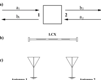
Figure 7 Schematic of the beam steering with an LCX antenna ... 17
Figure 8 Dipole antenna schematic (a) and radiation pattern (b). ... 18
Figure 9 (a) Loop antenna schematic and (b) E- and H- planes of the loop antenna radiation pattern ... 18
Figure 10 Schematic and radii of the fabricated 3-slit LCXs using hollow-core polymer-clad silica fibers for 2.4 GHz operation. ... 19
Figure 11 SEM picture of the multi-material fiber with a zoom on the inner silver coating in the inset ... 20
Figure 12 SEM pictures of the multimaterial fibers with external layer of Cu deposited using electroplating technique ... 21
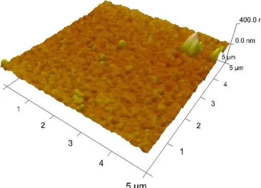
Figure 13 AFM (Atomic Force Microscope) pictures of the silver layer deposited using electroless technique. ... 22
Figure 14 Triangular corrugated surface in the Hammerstad and Jensen (H&J) model ... 23
Figure 15 Integration of multi-material fibers into textile hosts using conventional weaving process. Four specific fiber devices discussed in this work: textile LCX antenna (upper left), textile dipole antenna (middle), textile loop antenna (upper right inset) and textile touch-sensor (lower left insert). ... 24
Figure 16 (a) Concept of a two-port network. (b) A LCX fiber antenna and (c) a two antennas transmission system as examples of two-port networks. ... 27
Figure 17 (a) Fabricated LCX fiber antenna and (b) measured S11 and S21-parameters. ... 28
Figure 18 Measured (solid) and simulated (dashed) using ANSYS HFSS return loss (S11) for the dipole (black) and loop (red) textile integrated fiber antennas. ... 28
Figure 19 (a) Measured and (b) simulated radiation patterns along the E-plane and H-plane of the LCX textile fiber operating at 2.4 GHz frequency ... 29
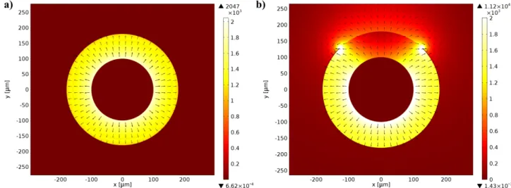
Figure 20 E-field simulation of the (a) propagation of a TEM-like mode inside the windowless segments of the LCX, and (b) coupling to radiation modes in the windowed segments. These numerical simulations were performed by Victor Bélanger-Garnier [82] ... 30
Figure 21 Radiation patterns at 2.4 GHz frequency for the (a) dipole and (b) loop textile antennas compared to (c) commercial ducky WiFi dipole antenna. Solid curves represent experimental measurements, dashed curves represent numerical simulations. Numerical simulations were performed by Mazen Khalil [81] ... 31
Figure 22 Schematic of the antenna gain measurements setup. An RF absorber is placed on the ground in order to avoid multipath interference. ... 31
Figure 23 Typical results of the gain measurements for the LCX (a) and dipole (b) textile integrated antennas. The S11 curves (blue) correspond to the return losses of the Aaronia HyperLog 7060 antenna and S22 curve (red) to the return losses of the antenna under study, the green S21 curve represents the power transmitted from one antenna to another over the 150 cm distance over an unobstructed path in the lab environment. ... 32
Figure 24 Real (blue) and imaginary (green) input impedance of (a) dipole, (b) loop and (c) LCX multi-material fiber antennas. ... 33
Figure 25 (a) Textile integrated antenna placed on the phantom during radiation pattern measurements in anechoic chamber (b) H-plane and (c) E-plane radiation patterns at 2.4 GHz for the commercial rubber ducky (black dotted line) and the textile dipole antenna: experimental (red) and numerical simulation (blue) results ... 35
Figure 26 Frequency shift of the dipole (a) and loop (b) textile antennas under stretch load ... 37
Figure 27 Frequency shift of the dipole (a) and loop (b) textile antennas under bending over cylinders of various radii ... 37
Figure 28 (a) LCX bending schematic (b) induced S11 frequency shift ... 38 Figure 29 LCX antenna radiation pattern distortion due to 90º arc bend (a) E-plane (b) H-plane 38
Figure 30 (a) Non-coated loop textile antenna test under direct water application. Experimental measurements (b) and numerical simulations (c) of the operating frequency shift depending on the water level. ... 39
Figure 31 (a) Hydrophobicity of the surface is characterized by the water contact angle (WCA) and sliding angle (SA) and depends on surface energy and structure (b) Macro image of a water droplet on the surface of polyimide tape coated with UED: WCA = 156.7º+/-2.6º, SA < 1º ... 41
Figure 32 Measurements of WCA and SA based on macro images in the case of the standalone multi-material fibers with UED coating (a) and textile samples with TextileShield coating (b) . 41
Figure 33 (a) Dipole antenna integrated into textile with superhydrophobic coating under direct water application. On the inset: water droplets purposely placed on UED coated multi-material fiber. Return loss S11 for textile dipole antenna under direct water application (b) before and (c) after superhydrophobic coating application. ... 42
Figure 34 (a) WCA of the wirelessly communicating textile sample with hydrophobic coatings after multiple washing cycles (b) Water-induced shift of the operating frequency after 10 and 20 washing cycles. ... 43
Figure 35 Numerical simulations of the SAR for the dipole (a) and loop (b) textile antennas at 0 dBm antenna transmission power, calculated using Ansys HFSS for the four-layer (skin-fat-muscle-bone) model ... 44
Figure 36 Results of the power loss measurements of the dipole (a) and loop (b) textile antennas. ... 45
Figure 37 Components of the BER transmission link test setup, including multi-material fiber loop textile antenna ... 48
Figure 38 Bit-error rate (BER) curves of a 2 Mbps communication link at -18 dBm transmitting power comprising wearable multi-material fiber textile antennas distanced from 1 to 10 meters in the following scenarios: on-body dipole textile antenna (blue line), on-body loop textile antenna (green line), on-body commercial dipole ducky antenna (red line), and off-body commercial dipole ducky antenna (black dotted line). ... 48
Figure 39 Received signal strength via Bluetooth from the textile prototype comprising both touch-sensing and RF-communicating functionalities, as function of distance. ... 49
Figure 40 (a) Capacitive touch sensing with multi-material fibers principle (b) Proof-of-concept prototype for user finger touch detection based on Atmel AT42QT1011 ... 51
Figure 41 Finger touch response of the capacitive textile touch-sensors fabricated using multi-material fibers connected to an Atmel AT42QT1011 device. The Signal-to-Noise ratio and time response were measured at SNR > 35 and < 1 millisecond, respectively. ... 51
Figure 42 Schematic of the textile prototype comprising both touch-sensing and RF-communicating functionalities, designed to relay wirelessly the user’s touch sensing textile signal to a smartphone. ... 53
Figure 43 (a) Spiral antenna design (b) operating frequency shift of the spiral antenna under 0-10% stretch... 56
Figure 44 (a) Schematic [111] Copyright, 2010, EMW Publishing and (b) operating principle [112] Copyright 2002 IEEE, of an IR-UWB sensing system. ... 57
List of Abbreviations
RFID Radio-frequency identification IR-UWB Impulse Radio Ultra Wide Band GPS Global Positioning System MIT Massachusetts Institute of Technology
EEE Electrical, Electronic, Electromechanical
RF Radio Frequency
EMG Electromyogram
EEG Electroencephalogram
ECG Electrocardiogram
LED Light Emitting Diode
FBG Fiber Bragg Grating
MRI Magnetic Resonance Imaging
PVDF Polyvinylidene fluoride
SC Super Capacitor
WTFT Wire thin film transistors
WECT Wire electrochemical transistors
CE Counter Electrodes
GSM Global System for Mobile Communications PCS Personal Communications Service WLAN Wireless Local Area Network
AMC Artificial Magnetic Conductor
CMOS Complementary metal–oxide–semiconductor
LCX Leaky Coaxial Cable
TEM Transverse Electromagnetic Mode TEOS Tetraethyl Orthosilicate
AFM Atomic Force Microscope GPIB General Purpose Information Bus
WCA Water Contact Angle
SA Sliding Angle
UED Ultra Ever Dry TM
RPM Rotations per minute
SAR Specific Absorption Rate
US FCC United States Federal Communications Commission ISM Industrial, Scientific and Medical radio band
WPAN Wireless Personal Area Network
BER Bit Error Rate
SNR Signal-to-Noise Ratio
TUI Touch User Interface
Acknowledgements
It would be very hard to acknowledge all the people that have contributed to this thesis. First of all, I would like to express my gratitude to my supervisors: research director Prof. Younès Messaddeq and co-director Prof. Sophie LaRochelle for their constant support, encouragement, and professional and scientific guidance during my PhD research. At the same time I would like to acknowledge fruitful collaboration with the group of Prof. Benoit Gosselin from the Department of Electrical and Computer Engineering.
All the time I was surrounded by wonderful colleagues: Victor Bélanger-Garnier, Mazen Khalil, Mickael Blais-Roberge, Jeff Viens and Bora Ung. I would like to thank them all for the helpful discussions, advices and mutual support. Also I would like to thank Kyle Bachus from Queen’s University, Ontario for the help with super-hydrophobic coatings deposition and characterization.
I also acknowledge jury members, Prof. John Ballato, Prof. Tigran Galstian and Prof. Martin Bernier, as well as the program director, Prof. Laurent Drissen for their time and valuable comments that contributed greatly to the improvement of the current thesis.
Finally, I would like to thank all the professors, employers and staff members of the Université Laval who taught me, answered my numerous questions and helped with the organization and administrative side.
Foreword
During my PhD, I mainly worked in the field of wirelessly communicating textiles. This work resulted in a number of the papers published in international peer-reviewed journals, conference proceedings and general media reports, the full list of which is given in Appendix B: List of publications. I am the first author and principal contributor of four journal papers presented below in chronological order, these papers form the core of the current thesis.
1. S. Gorgutsa, V. Bélanger-Garnier, B. Ung, J. Viens, B. Gosselin, S. LaRochelle, and Y. Messaddeq, "Novel Wireless-Communicating Textiles Made from Multi-Material and Minimally-Invasive Fibers," Sensors, vol. 14, pp. 19260-19274 (2014).
In this paper the concept of multi-material fibers, specifically of leaky coaxial design (LCX), was first introduced. Both I and Victor Belanger-Garnier performed all the experimental procedures, leaky coaxial design idea was proposed by Bora Ung. Jeff Viens and I wrote the paper. Professors Benoit Gosselin, Sophie LaRochelle and Younes Messaddeq provided many useful comments and suggestions during the discussions. The main results reported in this paper regarding LCX antennas are provided in Chapter 2 and Chapter 3 of the current thesis.
2. S. Gorgutsa, M. Khalil, V. Belanger-Garnier, J. Viens, B. Gosselin, S. LaRochelle, and Y. Messaddeq, "Emissive Properties of Wearable Wireless-Communicating Textiles Made From Multimaterial Fibers," IEEE Transactions on Antennas and Propagation, vol. 64, pp. 2457-2464 (2016).
In this paper I for the first time present and fully characterize loop textile fiber antenna. I had performed all the experimental part and wrote the paper, Mazen Khalil performed numerical simulations and Victor Belanger-Garnier contributed to fiber fabrication, and data transmission protocol. Jeff Viens, Professors Sophie LaRochelle and Younes Messaddeq provided many useful comments and suggestions during the discussion. The results reported in this paper represent the core part of Chapter 3.
3. S. Gorgutsa, M. Blais-Roberge, J. Viens, S. LaRochelle, and Y. Messaddeq, "User-Interactive and Wireless-Communicating RF Textiles," Advanced Materials Technologies (2016)
In this paper, I demonstrate user-interactive wirelessly communicating textiles that transmit touch-sensing event through Bluetooth protocol at 2.4 GHz. I fabricated the prototype, developed and characterized hardware and software parts. Both I and Jeff Viens wrote the paper. Mickael Blais-Roberge contributed to the fiber fabrication. Professors Sophie LaRochelle and Younes Messaddeq provided many useful comments and suggestions during the discussions. The results reported in this paper are provided in Chapter 3 and mainly in Chapter 4.
4. S. Gorgutsa, K. Bachus, S. LaRochelle, R. D. Oleschuk and Younes Messaddeq, "Washable hydrophobic smart textiles and multi-material fibers for wireless communication", submitted to Smart Material and Structures
In this paper, two types of hydrophobic coating were applied to the previously developed textile integrated fiber antennas and environmental endurance of the obtained prototypes was investigated. Kyle Bachus contributed to the idea and polyimide film characterization as well as proofreading the manuscript. I carried out most of experimental measurements and wrote the paper. Professors Sophie LaRochelle, Richard D. Oleschuk and Younes Messaddeq provided many useful comments and suggestions during the discussions. The main results regarding environmental endurance of the textile prototypes reported in this paper are provided in Chapter 3 and Chapter 4
Co-authors affiliations: Mickael Blais-Roberge
Centre for Optics Photonics and Lasers (COPL), Department of Chemistry,
Université Laval, Quebec G1V 0A6, QC, Canada
Victor Bélanger-Garnier, Mazen Khalil, Jeff Viens, Bora Ung – at the time of publication: Centre for Optics, Photonics and Lasers (COPL),
Department of Physics, Engineering Physics and Optics, Université Laval, Quebec, G1V 0A6, QC, Canada
Prof. Younès Messaddeq
Centre for Optics, Photonics and Lasers (COPL),
Department of Physics, Engineering Physics and Optics, Université Laval, Quebec, G1V 0A6, QC, Canada
Prof. Sophie LaRochelle
Centre for Optics, Photonics and Lasers (COPL), Department of Electrical and Computer Engineering, Université Laval, Quebec, GIV 0A6, QC, Canada Prof. Benoit Gosselin
Department of Electrical and Computer Engineering, Université Laval, Quebec, GIV 0A6, QC, Canada Kyle Bachus and Richard. D. Oleschuk
Department of Chemistry,
Introduction
Smart textiles have become a somewhat controversial topic of active research in the past decades with periodic spikes of interest following technological breakthroughs. On one hand, since textiles surround us 24/7 either as garments that we wear or as upholstery in our cars, homes, offices, etc., they are incredibly attractive as a platform for integration of various smart functionalities from biomedical sensors to user-interface elements. At the same time, one can observe a global shift from classical standalone computing to the concept of distributed computation (e.g. so-called thin clients and cloud storage). In this context, the computation power of the individual node, or smart textiles device, becomes progressively less important than the ability to relay data to the Internet. And this, in turn, enables variety of applications in continuous health monitoring [1] and more efficient work-force location and management [2]. On the other hand, despite all the advancements made in the field of smart textiles, including the progress in the domain of wire thin film [3] and electrochemical transistors [4] possibly leading to the development of an all-textile electronic circuits, such solutions rarely emerge from the lab and, except for some very specific cases, cannot be seen in the everyday life. In this thesis, I will first make an attempt to explain this seeming contradiction through the analysis of smart textiles evolution and current state of the art. Then I will propose and validate a new multi-material fiber approach to fabricate wirelessly communicating touch-sensitive smart textiles.
1.1 Literature review
1.1.1 Early trends in smart textiles
Early evolution and trends in smart textiles development can be divided into three periods:
In the first period, 1980s to 1997, the design approach can be regarded as technology driven. Most research and development efforts at that time focused on so-called ‘wearable computing’ technique [5], in which electronics is directly integrated on textiles - “E-textiles” [6],[7]. For example, with the support of US Naval Department in 1996, Georgia Tech has developed a garment called Wearable Motherboard (with the commercial name of Smart Shirt) [8],[9]. It was a fabric featuring woven electric wires and/or optical fibers that served as a flexible information buses. All these prototypes were based on the trends of miniaturisation of electronic devices and were more ‘portable’ rather than ‘wearable’. The same goes for the MIT wearable computer [10] or Randell’s CyberJacket [11] with integrated location sensors (GPS), displays, etc.
In the second period, early 2000s, collaborative development efforts between electronic and fashion fields intensified, resulting in several demonstrated prototypes. For example, the Cyberia project [12] in which researchers worked in collaboration with industrial designers in order to place electronics on the user’s body so that it fits without restricting the mobility. A special supporting vest was constructed between the coating and the lining to carry the weight of the devices. This way the mass of the electronics does not affect the posture of the garment and the wiring was carefully placed along the seams in order not to restrict user’s movements. Later, experts in textile and clothing initiated their own research and development activities [13]. Thus
the number of smart clothes available on the market increased dramatically, e.g. the North Face MET5TM jacket [14], Adidas smart shoes [15] and GapKid sweatshirts with embedded FM radio [16]. Although the applications became more wearable, most outcomes were still prototype garments. Since the technologies were either underdeveloped, e.g. Philips and Levis ICD+ jacket [17] and SCOTT eVast [18], or did not match requirements of the general public – practical applications of the optical fiber screens [19] on clothes were not clear.
The last decade brought about significant shift in an understanding of the definition and role of smart textiles. First, there came an understanding that even if people carry electronic devices around it does not necessarily mean that they want these devices to be part of their clothes. Therefore, instead of adhering to smart textile use for every day-to-day activities, many researchers turned their attention to the more specific tasks such as health monitoring [20], [21], resulting in prototypes as, for example, VivoMetrics Lifeshirt [22]. Second, it became necessary to differ ‘smart textiles’ from ‘wearable electronics’ in that wearable devices are merely contained and carried by clothing, whereas smart textiles have the functionality of wearable devices actually integrated into the fabric. This is an important distinction to make, because several commercial products marketed as smart textile are actually regular fabrics that envelope traditional electric, electronic, and/or electromechanical (EEE) devices.
In the next sections, I will review various smart textile solutions developed up to date with particular attention to the fiber-shaped electronics and textile antennas.
1.1.2 Smart textile functionalities of today
As of today, active functionalities in smart textiles can include power generation or storage, human interface elements, sensing devices, radio frequency (RF) emission/reception, various assistive technologies such as personal emergency response systems, augmentative communication, etc. The basic technological elements of smart textiles are conductive or semiconductive threads, various nanoelectronics applied directly to fibers, yarns, or woven elements, and chemical treatments that provide different features.
Indeed, a great variety of textile-integrated sensors have already been developed, for instance, temperature and humidity sensors [23]; shape-, pressure-, and movement-sensitive elements [24]; electrocardiogram (ECG) [25], electromyography (EMG) [26], and electro-encephalography (EEG) textile sensing devices [27]. Textiles that provide a seamless command-oriented user interface are a relatively new domain of investigation, however some capacitive touch sensing prototypes have been demonstrated [28] , [29], including those previously reported by our group [30]. Several examples of the different smart textile functionalities are presented in Figure 1. So-called e-fibers from [31] are shown in Figure 1 (a), they represent a classical attempt to adopt standard microelectronic solution (humidity or temperature sensors, an LED, etc.) to the flexible polyimide substrate in a form of 2x50 mm microstripes with additional encapsulation with Kapton or polyethylene layers. Authors of [32] used a different approach to create fiber Bragg grating (FBG) based strain sensor for respiration monitoring applications (see Figure 1 (b) and
(c)). The FBG fiber in this case was attached to the elastic part of the bondage in unobtrusive manner, it allowed stable respiration rate detection even during MRI scans, however this technique still naturally requires the FBG fiber to be plugged into an optical time-domain reflectometer.
Sensors for smart textiles can be both very simple and very complex by design. For example authors of [33], while still using the flexible substrates to compose layers of pressure, temperature, and humidity sensors arrays into the paper skin platform (see Figure 1 (d), (e)) were able to achieve great results using off-the shelf products and “garage” fabrication methods. Temperature sensor was either cut out of aluminum foil or drawn with the silver conductive pen on the Post-it paper. The resistance of the sensor varied depending on the ambient temperature due to phonon vibrations in the lattice structure of the metal, which reduced the ability of the material to properly conduct the electrical current. And for the pH sensor authors used an HB pencil to create the sensing graphite film. Operation principle is based on the redox reaction occurring between the graphite and hydroxyl ions in the corresponding aqueous solutions. When exposed to an alkaline solution, the carbonyl functional group goes through a reduction step (gaining electrons e−), decreasing the resistance with respect to neutral solution resistance. And when exposed to an acidic solution, the carbon based film goes through an oxidation step (loses e−) increasing the measured sensor resistance.
On the other side of the complexity spectra, there are resistive graphene channels and highly conductive silver nanowires (AgNWs) acting as electrodes on elastic PDMS substrate (see Figure 1 (f)) fabricated through a lithographic filtration method by Yan et al [34] for temperature sensing applications.
Figure 1 (a) Woven electronic fibers with sensing (humidity, temperature) and display (LED) functions [31].
Copyright 2010, WILEY-VCH Verlag GmbH & Co. KGaA, Weinheim. (b) Design of the FBG sensor integrated into a harness (c) for respiratory monitoring [32] (d) Schematic of 3D stacked paper skin structure composed of pressure, temperature, and humidity arrays. (e) Digital photograph of flexible temperature sensors array [33] Copyright 2016, WILEY-VCH Verlag GmbH & Co. KGaA, Weinheim (f) Images of the stretchable graphene thermistors at relaxed and twisted states [34] Copyright 2015 American Chemical Society (g) Thermochromic ink [35] (h) Liquid crystal ink [36] Copyright 2006, ACM New York, NY, USA and (i) optical fiber based textile displays [37] Copyright 2016 Optical Society of America (j) prototype mechanical energy harvesting dress [38] (l) the piezoelectricity harvesting garment module [39] Copyright 2016 IOP Publishing Ltd (m) flexible, solid electrolyte lithium battery stripes integrated into textiles [40] Copyright 2012 The Electrochemical Society.
During the past decade various textile based ink-displays (see Figure 1 (g)) became especially popular. One of the most commonly used ink for this type of displays is thermochromic ink that changes color based on the temperature. Typically such inks are deposited on textile [41], [42] and then are actuated by either electrically conductive yarn that is woven into the fabric or by incorporated wires. When powered up, the conductive yarn heats up and actuates the thermochromic ink to change the color. In Mosaic Textiles [36] (see Figure 1 (h)), authors use liquid crystal inks which work on the same principle as thermochromic inks, actuated also by the conductive yarn. However, such displays are limited, from one hand, by the size of the electrically conductive heaters, and by the lateral diffusion of heat emanating from the heaters. On the other hand, the displays that use only heating source such as body heat or conductive yarn without any cooling method, lack switching controllability and those that have a cooling system typically require high-cost and complex electronic elements. In 2008 Gauvreau et al [37]
implemented a different approach, polymer photonic band-gap Bragg fibers were integrated into textile (see Figure 1 (i)), under ambient illumination the fibers appear colored due to optical interference in their microstructure and the white color coupled in the low refractive index core is partly guided by the photonic bandgap effect, partly uniformly emitted through the cladding. The exact colors are controlled by the thickness of the Bragg fiber layers and can be adjusted during the fabrication.
In addition to sensing functionalities, there is a great interest in autonomous smart textiles that don’t require external power sources. The idea of harvesting body movement energy with the help of textiles had been investigate from numerous directions, from pure mechanical (see Figure 1 (j)) to electrostatic charge harvesting [43]. Naturally, exploiting materials that demonstrate strong piezoelectric effect (such as PVDF films, for instance) remains the most popular approach. In the latest (2016) work of Jin-Hee et al [39] the piezoelectricity harvesting garment module was placed on the user’s elbow (see Figure 1 (l)) and knee joint and demonstrated maximum of 39.53 V for 2 Hz frequency at the knee joint. Harvested energy can then be then stored in all-solid textile battery (from the safety point of view it is desirable to avoid liquid lithium-ion electrolytes) such as the one shown in Figure 1 (m). Those flexible batteries [40] have a soft artificial leather-like feel, although each strip produces only ~0.2-0.3 V (0.05 mA) they can be connected in series to produce enough power, for example, to light an LED.
1.1.3 Fiber‐shaped electronics
Due to the technical complexity of integration of the advanced electronic functionalities into a textile fiber itself, currently there are not many examples of such fibers. Historically, fiber super capacitors (SC) and batteries were among of the first explored so-called power source fibers, including fiber-shaped solarcells, fiber-shaped chargeable cells, self-regulating fiber-shaped fuel cells fiber-shaped thermoelectric power generators, and micro-fiber-based nanogenerators, etc. [44] Through the years different configurations of electrodes (symmetric/asymmetric), types of electrolytes (aqueous/solid) and materials for the separator layer were reported. In Figure 2 (a) a schematic representation of a typical fiber-based SC is given: two parallel fiber electrodes
(composed of a conductive fibrous substrate and electrochemically active materials) are packaged into a flexible plastic tube filled with electrolyte and a well-designed helical spacer wire [45]. In the same time one should not forget that such devices usually refer to the 10 um – 1 mm scale, their fabrication is quite complex, while their mechanical properties often do not allow to incorporate them directly into the textiles.
Also, several groups [3], [4], [46], [47] have recently demonstrated organic all-fiber transistors which can potentially allow creation of the electronic logic circuits by weaving. According to the articles published until now, fibre transistors can be divided into two large families: wire electrochemical transistors (WECTs) [4] and wire thin film transistors (WTFTs) [47]. In the case of WECTs (see Figure 2 (c)), the gate is on one yarn and other parts of transistor are on another yarn. These two separated yarns are glued to each other via an electrolyte solid which can be ion gel, poly ion liquid or the combination of these two electrolytes. The required control voltage for WECTs is typically about 2–3 V, however the switch time is on the scale of several tens of seconds. The advantage of WTFTs, which integrate the dielectric layer, the semiconductor layer and three electrodes (gate, source and drain) in/on one wire filament (see Figure 2(d)) is the short response time (<1 µs), the operating voltage is higher (several tens of volts).
Overall WTFTs had attracted probably more attention and developed techniques were implemented, for example in the recent (2015) photovoltaic textile prototype (see Figure 2 (e, f)) demonstrated by Zhang et al. The photovoltaic textile was composed of wire-type photoanodes and counter electrodes (CE), as schematically shown in Figure 2 (e). The wire-type photoanode was fabricated by growing a layer of ZnO nanoarrays on Mn-plated polymer wire as the substrate. After being dye sensitized, a layer of CuI was deposited onto the ZnO nanoarrays as the hole-transfer material. The CE was made of Cu-coated polymer wires. Under a standard light intensity of 100 mW cm −2, an open circuit voltage of 4.6 V and a short-circuit current density of 7.8 mA cm−2 were achieved, this corresponds to an efficiency of 1.3% for a single cell unit, which was enough to power a digital calculator (see Figure 2 (f)).
Finally, fiber-shaped textile pressure sensors have been actively explored for the great variety of applications from gait analysis to motion detection. Various operation types of pressure sensors (capacitive, piezoresistive, piezoelectric, optical) have been proposed, one recent remarkable all-fiber solution was demonstrated by Lee et al. [48] (see Figure 2 (b)). The textile pressure sensor is based on highly conductive (0.15 Ω cm–1) fibers coated with dielectric rubber materials, fabricated by coating poly(styrene-block-butadienstyrene) (SBS) polymer with Ag nanoparticles on the surface of poly(p-phenylene terephthalamide) (Kevlar) fiber. When two fibers like that are stacked perpendicularly, as shown in Figure 2 (b), they form a capacitive type pressure sensors in which deformation of the separating elastomer layer leads to great change in the capacitance. Authors report high sensitivity of 0.21 kPa−1, rapid response (~ 40 ms) and short relaxation times (~10 ms) of their sensor.
Figure 2 (a) Structure of the fiber-based supercapacitor [45] Copyright, 2014, WILEY-VCH Verlag GmbH & Co.
KGaA, Weinheim (b) Schematic illustration of the fiber pressure sensor [48] Copyright, 2015, WILEY-VCH Verlag GmbH & Co. KGaA, Weinheim (c) Topology of WECT fiber transistor [4] Copyright, 2011, The Electrochemical Society. (d) Photograph and optical microscope image of the fibriform OFET based on MIS microfiber embedded in the textile [47] Copyright, 2016, WILEY-VCH Verlag GmbH & Co. KGaA, Weinheim (e) Schematic illustrations of the photovoltaic textile and (f) Demonstration of the photovoltaic textile to power a digital calculator under natural solar irradiation [49]. Copyright, 2015, WILEY-VCH Verlag GmbH & Co. KGaA, Weinheim
1.1.4 Wireless communications – RF textile antennas
Textiles capable for wireless communication have been an increasingly popular topic in the recent years [50], [51], [52]. The use of fabric antennas has already been explored by some parties prompted by military or space applications; such antennas have been integrated into NASA Extravehicular Mobility Unit (EMU), EVA suit and the KORONA-M communications
system for the Russian Space Agency ORLAN-M EVA suit. Still the most common approach is based on various patch antenna designs and consists of either depositing conductive layers (copper) on some kind of flexible substrate (see Figure 3 (a-c)) or using conductive threads stitched on top of woven in specific shapes (see Figure 3 (d-f)).
Figure 3 (a) Copper coated conductive fabric textile patch antenna [53] Copyright 2016 SAGE Publications (b)
Dual-band Substrate Integrated Waveguide Antenna with a solar cell [52] Copyright 2014 IEEE. (c) Design and photograph of the stretchable monopole antenna with feed and support structure [54] Copyright 2015 WILEY-VCH Verlag GmbH & Co. KGaA, Weinheim (d) Textile patch antenna made with conductive threads [55] Copyright 2011 IEEE (e) Triband embroidered e-fiber antenna [51] Copyright 2012 IEEE (f) Coplanar waveguide monopole antenna with artificial magnetic conductor on body [56] Copyright 2016 Springer-Verlag Berlin Heidelberg (g) 3D weaved microstrip antenna [57] Copyright 2015 IEEE (h) Structure and photograph of an ink-jet printed antenna [50] Copyright 2014 IEEE.
Classical patch ‘textile’ antenna made from copper coated conductive fabric can be seen in Figure 3 (a). While the thickness of the conductive layer itself is typically very small (often on sub-mm scale) the bandwidth of a patch antenna is proportional to the electrical thickness of its substrate and the extent of the substrate, and therefore thicker (e.g. several mm) substrates are generally preferred [58]. Lemey et al. [52] proposed to benefit from the large area of the classical patch antennas and demonstrated hybrid platforms for RF, solar and body thermal energy harvesting (see Figure 3 (b)). The antenna itself is fabricated by a popular copper-on-polyimide technology. And while such combination might indeed be efficient in terms of energy harvesting, flexibility and possibility to actually wear such antennas seems to be questionable.
A stretchable antenna (see Figure 3 (с)) proposed in [54] featured copper-on-polyimide structure, with the elastic limit around 30%, gain of ~ 0 dB at 2.45 GHz frequency and was suitable for over 80 m wireless communication. Besides relatively low value of antenna gain it is also important to note a rather complicated fabrication procedure consisting of etching polyimide over aluminum mask with O2 plasma, Ar plasma copper layer etching and so on.
More classical approach, as it was mentioned, relies on the use of commercially available conductive threads (see Figure 3 (d)), for example in [55], the authors have used regular nylon threads coated with silver powder, and jeans and flannel fabric as substrate materials to sew an ultra-wideband (UWB) antenna that covers the frequency range from 3 GHz up to 20 GHz. The maximum gain was reported to be about 7.4 dB at 20 GHz. And the highest efficiency reached 97% at 12 GHz. However, at lower frequencies, which are most interesting in terms of applications relying on already existing civilian networks, around and below 3 GHz the efficiency appeared to be as low as 85%.
Wang et al. [51] have used conductive fibers embroidered on polymer substrates, that they called ‘e-fibers’. These e-fibers provide inherent mechanical strength, due to their polymer core (PBO - p-phenylene-2, 6-benzobisoxazole), and good electrical conductivity due to the silver coating. Moreover, authors proposed to group (twist) individual e-fibers together to improve their conductivity. Thus, the 332-strand e-fibers have a low resistivity of only 0.8 Ω/m. Authors then proposed using e-fibers to fabricate a planar multiband antenna (shown in Figure 3 (e)) designed to cover three communication bands, namely the GSM (850 MHz), PCS (1900 MHz), and WLAN (2450 MHz) bands. It was fabricated using automatic embroidery techniques on top of a fabric with a very high density of stiches (>70 stitches/cm2) and exhibited the gain of ~2 dBi. The dBi units are used to express gain of the antenna relative to the hypothetical isotropic radiator, for example, a lossless half-wavelength dipole has a gain of 2.15 dBi.
In the recent (2016) work of Kamardin et al. [56] it was proposed to enhance performance of the diamond dipole (see Figure 3 (f)) and coplanar waveguide monopole antennas by placing periodic conductive arrays on a grounded dielectric substrate, which then act like artificial magnetic conductor (AMC) and introduc a zero degrees reflection phase shift to incident waves thus increasing antenna gain from 2-3 dB to 6-7 dB. The antennas and AMC were made of commercially available Shieldit fabric.
The idea to hide a microstrip antenna between the layers of the fabric is not new, however the authors of [57] used 3D weaving technique to place the antenna between reinforced orthogonal glass fibers (see (g)), The measured return loss for the single-element antenna was -22.31 dB at the resonant frequency of 1.29 GHz and the gain of 0.47 dB at the frequency of 1.28 GHz.
In 2014 Whittow et al. [50] demonstrated a textile patch antenna produced by inkjet-printing technique. Silver or copper inkjet-printed antennas have been previously reported on paper [59], however on rough or porous textiles it is challenging to do inkjet printing due to the small thickness of the printed layer. To overcome this constrain, authors had pre-treated the fabric with an intermediate screen-printed interface layer (shown in solid blue in Figure 3 (h)), then deposited the two conductive layers using commercially available inkjet-printable silver (U5714). The antenna had an area of 90x90 mm2 and a probe feed was implemented by using an ultra-small flexible coaxial cable of 1.32 mm attached by silver epoxy paint. The antenna was designed for the 2.4 GHz frequency, the efficiency of the antenna was measured experimentally and was estimated as 57%, gain of the antenna was 5 dBi at 2.48 GHz. Inkjet-printed antennas are known to be sensitive to bending as the inkjet layer can be damaged by compressing and tensioning the conducting surface originating from the bend around cylindrical structures (like human body or arm). Authors show that the antenna with only one ink-jet printed layer when bent over a 70 mm cylinder becomes extremely lossy and does not function at all. The antenna with two ink-jet layers detunes out from the designed frequency.
1.1.5 Summary
Analysis of the previous research in the field of smart textiles reveals that it has foundation in different research disciplines, such as textile design and technology, chemistry, physics, material science, computer science and technology, analog and digital electronics, wireless communication, human interfaces, signal processing, ergonomics, etc. Nevertheless, until recently, it has been driven mainly by the progress in microelectronics and has leveraged CMOS approach to obtain smart textile functionalities for immediate applications. However, several practical considerations limit wide adoption of the smart textiles out of the lab environment, namely manufacturability (the fabrication process should be scalable to mass production), integration (currently most of the solutions are introduced on the post-processing step, not during textile fabrication), environmental endurance (even smart textile should be easily washable and withstand stretching and bending) and user comfort (ideally smart textiles should preserve comfort and cosmetic appeal of the traditional garments).
Addressing individual fibers, as building blocks of the smart textiles had already proved to be successful in the field of power-generating fibers and fiber-based transistors, however, up to now, the field of textile antennas remains heavily under the influence of the microstrip and patch antenna designs, which are ill-suited for textile integration due to fundamental requirement of the thick substrates. In the following section it will be shown that multi-material fibers can be used to overcome this limitation and address the above mentioned practical issues.
1.2 Multimaterial fibers – research opportunity for the next generation of smart textiles
In 2004 researches at MIT have demonstrated [60] the ability to interface materials with widely disparate electrical and optical properties in a single fiber, to achieve submicrometer features and fabricate arbitrary geometries over extended fiber lengths. Later, in 2006 [61], they have successfully combined four different materials, namely two amorphous chalcogenide semiconductors (As2Se3 and Ge15As25Se15Te45; GAST), a metal (Sn) and a polymer (polyethersulphone, PES), in a macroscopic preform rod that was later drawn into fiber. The hybrid fiber shown in Figure 4, for example, has two functional components: (i) a hollow-core photonic bandgap (PBG) waveguide for CO2 laser transmission; and (ii) three metal– semiconductor– metal (MSM) thermal detector elements for temperature sensing.
Figure 4 Multimaterial fiber approach developed at MIT [61].
Thus it has been already shown that functionalized multimaterial fibers may be delivered at length scales and in a mechanically flexible form associated with optical fibers [62], addressing the first of the above mentioned constrains – manufacturability. From the previous research [37] and my own personal experience [28] in the group of Prof. M. Skorobogatiy at Ecole Polytechnique de Montreal, it became clear to me that optical silica fibers of 100-300 µm diameter can be used directly in the traditional industrial looms, thus solving the integration issue on the stage of textile fabrication.
Another appealing feature of the fiber-based approach is that by combining insulating, semiconducting, and conducting materials into a well-defined geometry, practically all desired smart textile functionalities can be obtained within the fibers themselves. And the ability to use chemically stable, mechanically strong, and thermally robust fiber cladding materials (such as silica glass and high-Tg polymers) allows shielding of the smart embedded elements from water
and chemical exposure, physical stress, and extreme temperatures. For example, already in 2002, Fokine et al [63] have shown that molten Bi (43%) and Sn (57%) alloy at ~ 170° C can be pumped into silica glass capillaries at 8 atm pressure to form long (up to 22 m) internal electrodes for electro-optic switching applications. Finally, multi-material fiber approach follows the concept of minimally-invasive integration, thus maintaining user comfort and cosmetic appeal associated with the regular garments.
Overall, the proposed approach, which is to use the preform-based optical fiber-drawing technique in order to fabricate functionalized smart multi-material fibers, particularly those acting as RF antennas, provides unique research opportunity. First of all, the field of the smart textiles itself and its applications in mobile wireless communications in particular, is a new, fast growing and interdisciplinary domain. Second, as it was shown in the literature review section, to the best of my knowledge, up-to-date there has been no in-fiber antennas of any kind reported. All reported solutions rely on patch antenna designs of different kinds. At the same time, this project clearly benefits from a well-established optical fiber manufacturing industry, in general, and a vast multidisciplinary (chemistry, glass science, antenna design, microelectronics) expertise obtained at the Centre for Optics, Photonics and Lasers (COPL), Department of Physics, Engineering Physics and Optics, Université Laval.
In the following section, I will formulate general and specific objectives of my research project, and outline the structure of the current thesis.
1.3 Research objective and organization of the thesis
1.3.1 Research objective and strategy
The main objective of this research project is to develop next-generation fiber and textile devices that lend themselves to RF-emission adaptable to existing civilian broadband mobile infrastructures. This project is based on an innovative approach to optical fiber technology and pursues integration of innovative fiber technologies into textiles. The strategy to successfully achieve the set goal consists of the three consecutive stages described below.
First, it is needed to design RF antennas based on single fiber strand that can be easily implemented in the fiber form and integrated into textiles. Classical center fed dipole and loop antennas are the first ones to come to mind when speaking of wire-shaped antennas. At the same time, antennas based on the concept of leaky coaxial cables (LCX) are particularly attractive from the integration point of view. Therefore, these three antenna types were chosen as potential candidates for numerical simulations and theoretical analysis.
The next step is the fabrication of the multi-material fibers. It represents several challenges: first, it is needed to identify conductor and insulator materials that can be co-integrated within specific fiber cross-section geometry to provide an electromagnetic resonance at the desired radio frequencies. Second, the combination of these materials should be chemically and mechanically stable, namely, deposited films should have low electrical resistance, strong adhesion to dielectric fiber surface, low surface roughness and great uniformity.
Finally, it is important not only to integrate multi-material fibers within textiles without damaging them, but is also needed to demonstrate RF emission at the desired frequency. In order to prove feasibility of the multi-material fiber approach in general, it is crucial, on one hand, for the RF-emissive performance of the developed textiles to be comparable to classical ‘rigid’ solutions. And on the other hand, they should demonstrate advantages over these solutions in terms of body proximity effects, mechanical flexibility and environmental endurance.
1.3.2 Thesis structure
As it was mentioned in the Foreword, my PhD research activities have resulted in multiple publications (full list available in Appendix B). However partly due to limitations of the journals, and partly due to the nature of the conducted work with a somewhat un-common and extremely innovative research field, a simple presentation of the published papers is not enough. For instance some model data on the effect of surface roughness of the deposited metal films, results of fiber-antenna bending and details on communication test algorithms were never published. I believe that these aspects should still be clarified, especially for the reader unfamiliar with the field, so that the proposed novel approach can be clearly explained and justified. Thus the originals of the published papers, as they appeared in peer-reviewed journals are presented in Appendix A.
In Chapter 2, I first provide basic theoretical background and resulting design considerations for different investigated antenna types. Next, I discuss the fabrication techniques used to produce fiber antennas and actual integration of these antennas into textile.
Chapter 3 is the core of this thesis and is devoted to experimental and numerical characterization of the developed textile integrated antennas. I discuss RF emissive properties, mechanical stability under stretch and bending loads, as well as environmental endurance in terms of superhydrophobic coatings and, finally, safety for the user. At all stages proposed fiber antennas are directly compared to the existing commercial solutions.
In Chapter 4, I study performance of the textile prototypes in the real world application scenarios for actual data transmission through the WLAN and Bluetooth wireless networks and show that, first of all, their performance is directly comparable with classical solutions and adequately addresses requirements of short-range RF transmission systems. Additionally, I demonstrate the same type of multi-material fiber can be used for user touch detection.
Chapter 5 contains a summary and general assessment of the achieved results along with the discussion on possible future research directions, namely applications to biosensing (heart and breathing rate detection).
Fiber antenna basics and fabrication
This section starts with brief theoretical background for the explored fiber-shaped antennas, namely LCX, dipole and loop. It is followed by the description of the multi-material fiber fabrication techniques, with the main focus on copper electroplating and electroless silver deposition. Special attention is also given to the roughness of the metal layers and its possible effect on fiber antenna performance. The chapter is concluded by presentation of the textile integration method.
2.1 LCX antenna
Leaky Coaxial Cables (LCXs) are known for their capability of distributing radio waves in tunnels, mines, underpasses, and many other confined environments, with smooth electrical field coverage, [64]. The operating principle of leaky-wave antennas has been known for many years [65]. The earliest example of such an antenna was a rectangular waveguide with a continuous slit cut along its side [66] (see Figure 5 (a)).
Figure 5 (a) Rectangular leaky wave antenna (b) condition for the leaky wave component to exist ( < k0) Let us consider conditions under which controllable leakage of the guided wave through the slit will occur. Assuming a guided wave (e-jz) traveling in the +z direction with phase constant
see Figure 5 (b) it will produce a leaky wave in the x direction (kx) if:
2 2 2
0
x
k k (1)
From (1), the leaky wave will start to appear if and only if kx becomes a real number. As a result,
< k0 is the condition for generating a real leaky wave.
Now let us consider the coaxial cable configuration, the dominant mode in the pure dielectric rod is classified as a slow wave ( > k0), meaning that the leaky waves cannot be formed from the dominant mode even if there is an aperture in the structure. It is the periodic modulation of the guided-wave structures that allows the generation of leakage.
Figure 6 Schematic of the leaky coaxial antenna (LCX).
When a periodic array of slits is added (as shown in Figure 6), the periodicity introduces an infinite number of space harmonics according to Floquet’s theorem, each characterized by phase constants n:
0 2
nd P n
(2)
where d is the periodic length of the guided-wave structure and 0 , the fundamental space
harmonic, is the phase constant of the dominant mode of the original uniform dielectric waveguide, but now perturbed somewhat in value because of the addition of the strips. From (2), even if the dominant mode (the fundamental space harmonic) is slow wave, some other space harmonics may be fast. The phase constant of the first space harmonic (n =-1) can be written as
1 0
2 P
(3)
By carefully designing a leaky-wave structure over a certain frequency range with specific geometrical conditions, the condition of -1 < k0 can be fulfilled. Since a single beam is usually needed, the structure is designed so that only the first space harmonic (n =-1) is fast.
The beam direction of the periodic leaky-wave antenna can be expressed as: 1 0 sin m k (4)
where θm is the angle of the maximum of the beam, measured from the broadside direction. From
(4), when -k0 < -1 < 0, the beam of the periodic leaky wave antenna is directed into the backward area. As frequency increases, the beam swings up from the backward end fires towards the broadside (see Figure 7), then through the broadside into the forward quadrant.
Figure 7 Schematic of the beam steering with an LCX antenna
There are very few studies on the use of small-scale LCXs for mobile communications or biomedical systems [67], [68]. The periodic distance P and the relative permittivity r of the
dielectric must be carefully designed in accordance with the frequency constraints of the wireless networks as well as with dimensional constraints of the garment industry. Usually, the theoretical modeling considers an infinitely long coaxial cable that supports a single TEM propagation mode. This allows the use of Bloch-Floquet theory [69], which greatly eases the analysis of the radiation properties. The geometrical parameters of the LCX are generally chosen as to allow only the m = −1 fundamental spatial harmonic [70], which radiates at an angle of:
1 1 1 sin sin m r r m m P P (5)This mode of operation provides a nearly transverse (i.e. broadside) radiation pattern. And the frequency range of LCX antenna is determined by P and r, defined for the m = −1 fundamental
spatial harmonic by the inequality:
r 1
r 1
c c
f
P P
(6)
Using polymer-clad silica fibers (r ~ 3.7) and a periodic distance P in the range from 1–40 cm
the LCXs can be designed for carrier frequencies in the range of 0.8–5.0 GHz, respectively, with the WLAN 802.11b/g/n 2.4 GHz ISM band in mind. They can also be scaled according to any desired carrier frequency of most wireless networks and such dimensions are also compatible with typical clothing sizes. A transmission loss of a few dB/m for the coaxial cable is acceptable for textile antenna applications since typical dimensions are below the meter range.
2.2 Wire‐shaped antennas
Dipole antenna is probably one of the simplest and most widely used classes of antennas, which is naturally ideally suited for fiber antennas. In general radio engineering, the term dipole usually means a half-wave dipole (center-fed) that consists of a pair of tubular conductors aligned in tandem so that there is a small feeding gap at the center (Figure 8 (a)). It is well known that radiating frequency, f, of the half-wave dipole is related to its length, l, as 1 1
2 d 2 c l k f , where
λd is corresponding radiation wavelength, k – wavenumber and c – speed of light. The dipole
antenna is an example of a vertically polarized omnidirectional antenna - its radiation pattern is independent from the azimuthal angle Figure 8 (b).
Figure 8 Dipole antenna schematic (a) and radiation pattern (b).
Another fiber antenna shape is the loop antenna (see Figure 9) which becomes resonant as the perimeter of the loop approaches one wavelength in size. It has low radiation resistance but high reactance, so its input impedance is difficult to match to a transmitter and it is most often used as receiver antenna, where impedance mismatch loss can be tolerated. However, in case of on-body applications, loop antennas have one important advantage. The human body has a rather large value for permittivity and a finite conductivity [71], but is not really magnetic. So its influence on the performance of the loop antenna (sometimes also called ‘magnetic dipole’) is expected to be low.
Figure 9 (a) Loop antenna schematic and (b) E- and H- planes of the loop antenna radiation pattern
In Figure 9 (b), the radiation pattern of the loop antenna is shown in the E- and H- plane representation. In case of linearly polarized antennas, such as loops and dipoles, the plane containing the electric field vector is called E-plane, and the one containing magnetic field – H-plane. Sometimes elevation and azimuth formalism is also used, for a vertically polarized antenna E-plane usually coincides with the elevation plane and H-plane with the azimuthal plane. One can notice that the E- and H- planes of dipole and loop antennas are in fact inverted with respect to each other.
2.3 Fiber fabrication
As it was mentioned earlier, in principle, fabrication of conductive internal electrodes can be achieved with low melting temperature metals and alloys [63]. However, to avoid usage of complex high pressure / temperature systems another approach was chosen, based on improving concepts of liquid state metal films deposition that have already been demonstrated [72], [73]. Thus LCX fiber antennas were fabricated using a hollow-core silica fiber with an inner radius of 100 m and outer radius of 181 m (purchased from Polymicro Technologies), coated with an 18 m thick polyimide layer, the inner and outer surfaces of the fiber were coated with thin films of silver and copper metal, respectively, as schematized in Figure 10. Size and position of the slits (shown in Figure 10) were chosen according to LCX antenna theory described earlier and fabricated by simple masking corresponding areas during copper deposition. Additionally a 20 m layer of protective acrylic coating was deposited over the fiber except for two 2 mm endpoints to allow for electrical connections that were made manually by inserting and direct soldering a tin-coated copper wire (ø 127 µm).
Figure 10 Schematic and radii of the fabricated 3-slit LCXs using hollow-core polymer-clad silica fibers for
2.4 GHz operation.
Dipole and loop fiber antennas, as well as fiber touch sensor, were fabricated using the same hollow-core silica fibers and using the same silver deposition technique (described in full details hereafter) of the inner electrode. Since in this case there is no need for external electrode, the polyimide protective coating was left intact.
![Figure 3 (a) Copper coated conductive fabric textile patch antenna [53] Copyright 2016 SAGE Publications (b) Dual-band Substrate Integrated Waveguide Antenna with a solar cell [52] Copyright 2014 IEEE](https://thumb-eu.123doks.com/thumbv2/123doknet/6439013.170879/26.918.153.747.217.887/conductive-copyright-publications-substrate-integrated-waveguide-antenna-copyright.webp)