HAL Id: hal-00317363
https://hal.archives-ouvertes.fr/hal-00317363
Submitted on 1 Jan 2002
HAL is a multi-disciplinary open access
archive for the deposit and dissemination of
sci-entific research documents, whether they are
pub-lished or not. The documents may come from
teaching and research institutions in France or
abroad, or from public or private research centers.
L’archive ouverte pluridisciplinaire HAL, est
destinée au dépôt et à la diffusion de documents
scientifiques de niveau recherche, publiés ou non,
émanant des établissements d’enseignement et de
recherche français ou étrangers, des laboratoires
publics ou privés.
Earth’s magnetosphere. 1. Statistical results
H. Laakso, R. Pfaff, P. Janhunen
To cite this version:
H. Laakso, R. Pfaff, P. Janhunen. Polar observations of electron density distribution in the Earth’s
magnetosphere. 1. Statistical results. Annales Geophysicae, European Geosciences Union, 2002, 20
(11), pp.1711-1724. �hal-00317363�
Annales
Geophysicae
Polar observations of electron density distribution in the Earth’s
magnetosphere. 1. Statistical results
H. Laakso1, R. Pfaff2, and P. Janhunen3
1ESA Space Science Department, Noordwijk, Netherlands
2NASA Goddard Space Flight Center, Code 696, Greenbelt, MD, USA 3Finnish Meteorological Institute, Geophysics Research, Helsinki, Sweden
Received: 3 September 2001 – Revised: 3 July 2002 – Accepted: 10 July 2002
Abstract. Forty-five months of continuous spacecraft
poten-tial measurements from the Polar satellite are used to study the average electron density in the magnetosphere and its de-pendence on geomagnetic activity and season. These mea-surements offer a straightforward, passive method for mon-itoring the total electron density in the magnetosphere, with high time resolution and a density range that covers many orders of magnitude. Within its polar orbit with geocentric perigee and apogee of 1.8 and 9.0 RE, respectively, Polar
en-counters a number of key plasma regions of the magneto-sphere, such as the polar cap, cusp, plasmapause, and auroral zone that are clearly identified in the statistical averages pre-sented here. The polar cap density behaves quite systemati-cally with season. At low distance (∼2 RE), the density is an
order of magnitude higher in summer than in winter; at high distance (>4 RE), the variation is somewhat smaller. Along
a magnetic field line the density declines between these two altitudes by a factor of 10–20 in winter and by a factor of 200–1000 in summer. A likely explanation for the large gra-dient in the summer is a high density of heavy ions that are gravitationally bound in the low-altitude polar cap. The geo-magnetic effects are also significant in the polar cap, with the average density being an order of magnitude larger for high
Kp; for an individual case, the polar cap density may increase even more dramatically. The plasma density in the cusp is controlled primarily by the solar wind variables, but never-theless, they can be characterized to some extent in terms of the Kpindex. We also investigate the local time variation of the average density at the geosynchronous distance that ap-pears to be in accordance with previous geostationary obser-vations. The average density decreases with increasing Kp at all MLT sectors, except at 14–17 MLT, where the average density remains constant. At all MLT sectors the range of the density varies by more than 3 orders of magnitude, since the geostationary orbit may cut through different plasma regions, such as the plasma sheet, trough, and plasmasphere.
Correspondence to: H. Laakso (hlaakso@so.estec.esa.nl)
Key words. Magnetospheric physics (magnetospheric
con-figuration and dynamics; plasmasphere; polar cap phenom-ena)
1 Introduction
The total electron number density is a key parameter needed for both characterizing and understanding the structure and dynamics of the Earth’s magnetosphere. The spatial varia-tion of the electron density and its temporal evoluvaria-tion dur-ing different geomagnetic conditions and seasons reveal nu-merous fundamental processes concerning the Earth’s space environment and how it responds to energy and momentum transfer, both in response to the solar wind, as well as to inter-nal sources, such as the ionosphere (e.g. Moore and Delcourt, 1995). Although the electron density in the magnetosphere is known in a general sense from case studies, large-scale, systematic studies of the electron density distribution in the magnetosphere have been performed only a few times in the past (e.g. Escoubet et al., 1997; Laakso et al., 1997; John-son et al., 2001). Consequently, the models of the magne-tospheric plasma density are much poorer than those for the magnetic field. The latter have been under development for many decades (e.g. Tsyganenko and Stern, 1996) and have benefited from the fact that almost every scientific satellite in the magnetosphere has carried a magnetometer. Plasma den-sity measurements are more difficult to obtain in a systematic sense from a single instrument, since the plasma density and temperature might typically vary over several orders of mag-nitude.
There are a number of techniques for measuring the total plasma number density, but each technique has its own limi-tations. Spacecraft charging seriously limits the direct detec-tion of low-energy charged particles and must be taken into account for a variety of instruments. Furthermore, photoelec-trons and secondary elecphotoelec-trons can cause a significant increase
in the density around the spacecraft which degrades the qual-ity of low-energy electron densqual-ity measurements. Plasma wave cutoffs and resonances can provide excellent measure-ments of the plasma density if such waves are detectable, which is not always the case in tenuous plasmas. Also, some-times, these waves do not represent the local plasma where the satellite is located. Electric field double probe instru-ments (EFI) provide measureinstru-ments of the potential differ-ence between a sensor and the satellite body, which depend on the total electron density, as we discuss below.
In addition to electric field measurements, electric field double probes typically monitor the potential difference (1V ) between each sensor and the satellite (Mozer et al., 1978; Pedersen et al., 1978). In the case of the Polar satel-lite, the probe potential is kept artificially near the local plasma potential by means of a bias current. The measured potential difference, therefore, is approximately the space-craft potential (with respect to the plasma potential) which is, on the other hand, proportional to the electron density and only weakly dependent on the electron temperature (Laakso and Pedersen, 1998). Therefore, 1V measurements offer a straightforward, passive method for monitoring the variation of the total electron density in the magnetosphere with a high time resolution (e.g. less than 1 msec) and a range that cov-ers many ordcov-ers of magnitude. The accuracy of this tech-nique remains valid even for densities well below 1 cm−3, as shown by numerous in situ measurements in the magne-tosphere (e.g. Pedersen, 1995, and references therein). This technique has been applied in several studies of electron den-sity variations in the magnetosphere (e.g. Escoubet et al., 1997; Laakso et al., 1997; Johnson et al., 2001).
This paper deals with the distribution of the average elec-tron density in the magnetosphere, using 45 months of lite potential data from the EFI experiment on the Polar satel-lite. These data cover 107data points (one-minute averages are used here) distributed between 2 and 9 REgeocentric
dis-tances along Polar’s polar orbit. The plasma regions that di-rectly emerge from the statistical pictures are the cusp, polar cap, and plasmasphere. The data set allows us to investi-gate the variation of the electron density in these and many other regions. The present study contains a detailed analysis of the polar cap density variation with season, altitude, and geomagnetic activity. We also investigate how the average electron density varies at L = 6.6, that is, at the geosyn-chronous distance, as a function of MLT and geomagnetic activity. In the second part of this study, Laakso et al. (2002) present high-resolution data from individual orbits and ex-amine in more detail some specific magnetospheric regions, such as the cusp, plasmapause, trough, and polar cap.
2 Instrumentation
We use measurements gathered by the electric field instru-ment (EFI) on the Polar satellite. Polar was launched on 24 February 1996 into a 90◦ inclination orbit with a 9 RE
apogee (initially over the Northern Hemisphere), a 1.8 RE
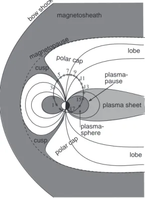
* * * ********* * * * * * * plasma sheet magnetosheath bow shock cusp cusp plasma-sphere magnetopause lobe 1 3 5 7 9 11 13 15 17 plasma-pause polar cap polar cap lobe
Fig. 1. Schematic drawing of the Earth’s magnetosphere in the noon-midnight meridian. A solid line presents a Polar trajectory; asterisks give the spacecraft’s position at one-hour intervals.
perigee (initially over the Southern Hemisphere), and an or-bital period of about 18 h. The oror-bital plane rotates about the Earth with respect to the Sun in one year so that all local times are covered in a 6-month period. Figure 1 presents a schematic drawing of the magnetosphere at the noon-midnight meridian and a Polar orbit, where asterisks mark the position of the satellite at one hour intervals.
2.1 Derivation of total electron density
The Polar EFI experiment (Harvey et al., 1995) consists of three pairs of double probe antennas oriented perpendicular to each other. The potential difference between each probe (probe potential = Vp) and the satellite (satellite potential = Vs) is
1Vps=Vp−Vs, (1)
where p corresponds to the sensor number, and in this case,
p = 1–6. These are sampled at a high-time resolution (10 or 20 Hz, typically), which allows us to follow rapid elec-tron density variations along the Polar trajectory. In burst mode the sampling rate can be up to 8000 samples per sec-ond, in which case very fast density variations can be moni-tored, which are commonly observed, for instance, on auroral field lines (Laakso et al., 1997).
To minimize the contributions of the DC electric fields on the spacecraft potential measurements, the measurements of
-30 -25 -20 -15 -10 -5 0 ∆ V12s (volts)
Polar EFI
April 29, 1996
UT MLT L shell Inv Lat (˚) 02:00 11:20 7.3 68.3 04:00 11:53 39.7 80.9 06:00 14:36 209.3 86 08:00 19:30 131.2 85 10:00 21:17 38.8 80.8 12:00 22:08 16.6 75.8 14:00 22:44 8.2 69.6 16:00 23:10 4.1 60.4 18:00 11:32 2.4 49.8 6 1 0.4 0.2 0.1 200 density (cm –3 ) PS - plasmasphere PP - plasmapause DAY - dayside magnetosphere AUR - northern auroral zone SH - southern polar cap & auroral zonePSPP DAY cusp northern polar cap AURPP PS PP PPSH PS
Fig. 2. Negative spacecraft potential (1V12s) measurements of the Polar EFI instrument during one orbit on 29 April 1996, when the Polar’s
orbital plane was near to the midnight-noon meridional plane (for the orbit, see Fig. 1). The right-hand side presents the approximate plasma densities.
the two opposing probes are averaged such that:
(1V1s+1V2s)/2 = (V1+V2)/2 − Vs . (2)
We thus adopt the following notation here: 1V12s =
(1V1s+1V2s)/2.
Numerical results show that in a tenuous environment,
1Vps and log(Ne) are related to each other in a way which
depends on the temperatures of escaping photoelectrons (Laakso and Pedersen, 1998). Although the magnitude of the saturation photoelectron current is not significant for this relationship, it is essential that the photoelectron current ex-ceeds the sum of the bias current and the ambient electron current. Otherwise, this method of measuring the density fails. In other words, high plasma densities cannot be deter-mined with this technique. The electron temperature Tealso
affects the value of 1Vps. However, as shown by Laakso
and Pedersen (1998), as long as Teremains in the 1–1000 eV
regime, it only gives a minor contribution. The derived and real plasma densities are estimated to differ generally only by less than a factor of 2–3 (mainly due to the differences in
Tenot taken into account).
The relationship between 1Vps and Ne can be
qualita-tively explained as follows: when the density is less than
∼500 cm−3, Vs is positive and closely related to the
elec-tron density. At the same time Vpis kept artificially close to
the local plasma potential by means of a bias current which is an electron flux injected from the spacecraft to the probe (Pedersen et al., 1984). Since Vp differs from the plasma
potential by less than a few volts in the magnetosphere, the measured 1Vps is thus very close to −Vs. When the
den-sity increases, Vs decreases (and −Vs increases) whereas Vp
remains almost unchanged due to the bias current. There-fore, the factor (V1+V2)/2 in Eq. (2) is practically constant,
and does not present any concern regarding the use of this technique. In high density (above ∼500 cm−3in the Earth’s magnetosphere), (V1+V2)/2 becomes negative, and then the
1Vpsmeasurements can no longer be used as an indicator of
the bulk electron density (Laakso and Pedersen, 1998). The actual limit, however, depends on the bias current applied to the sensor and the photoelectron characteristics.
The relationship between 1Vpsand the total electron
den-sity has been empirically studied and modeled recently, us-ing double probe measurements from the GEOS and ISEE satellites (Pedersen, 1995; Escoubet et al., 1997). Using 10 months of Polar data from the EFI and HYDRA instruments, Scudder et al. (2000) performed a detailed investigation of this relationship. In fact, the present study utilizes their de-rived relationship, which is quite similar to the relationships found for other satellites (Pedersen, 1995).
2.2 Variation of 1V12salong Polar’s orbit
Figure 2 shows an example of the 1V12svariation along one
full orbit on 29 April 1996, when Polar’s orbital plane was near the noon-midnight meridian (see Fig. 1); the density scale is given on the right-hand side. Notice that the high-density regions appear as weakly negative 1V12s values. In
the plasmasphere 1V12s is more than −2 V, but during the
outbound crossing of the plasmapause it rapidly decreases by several volts. In this voltage range, such a small change corresponds to a large density decline by a few orders of magnitude. The characteristics of the density gradient at the plasmapause can, in general, vary quite significantly. For instance, in Fig. 2 the plasmapause appears very clearly at about 14:45 UT near midnight, but less clearly at 01:45 UT near noon. This point with other examples is investigated in more detail in the companion paper (Laakso et al., 2002).
An interesting feature in Fig. 2 is the crossing of the cusp at 03:30–04:15 UT, during which 1V12 sincreases from
−7 V to −2.5 V. This corresponds to a density increase from 2 to 50 cm−3. Marklund et al. (1990) observed similar vari-ations across the cusp with the Viking satellite at somewhat
lower altitudes. Poleward of the cusp, centred at ∼05:00 UT, another density enhancement occurs, which is possibly re-lated to the inner edge of the high-latitude boundary layer or the plasma mantle (Rosenbauer et al., 1975).
In the polar cap regions, which map into the lobes of the magnetotail, 1V12s becomes strongly negative. In Fig. 2,
1V12s decreases to −25 V (which corresponds to densities
below ∼0.1 cm−3) (Scudder et al., 2000). Quite frequently, the potential in the polar cap is between −30 and −40 V and can sometimes go below −50 V (i.e. the density is near 0.01 cm−3). Figure 2 also shows large-scale density struc-tures in the high-altitude polar cap region. Such variations are commonly observed, and are likely a mixture of temporal and spatial structures, related to solar wind-magnetosphere-ionosphere coupling processes. Over the Southern Hemi-sphere the satellite crosses the polar cap very quickly (17:20– 17:30 UT). Here the satellite’s altitude is only 6000 km or less, and 1V12s varies between −5 and −12 V,
correspond-ing to a density range 0.8–2 cm−3. Just prior to this, the spacecraft is above the southern auroral oval, where 1V12s
is below −20 V due to a low-altitude auroral cavity (corre-sponding to a density of 0.2 cm−3).
3 Statistical results
We now use spacecraft potential measurements from 1 April 1996 to 31 December 1999, to provide average density distri-butions within the magnetosphere. Since the magnetospheric structure strongly depends on the geomagnetic activity, the measurements are binned by 3-hour Kpindex.
Before the spacecraft potential data are used in the statis-tical analysis, intervals with poor data quality must be re-moved. Such intervals result from a variety of reasons. First, the Polar satellite carries a satellite potential control device, called PSI (Moore et al., 1995), which is used at selected in-tervals to keep the satellite at a constant low potential, what-ever the ambient plasma density. Therefore, all intervals of PSI operation have been deleted from this study. Second, the EFI pre-amplifiers oscillate during times of high electron fluxes (F. Mozer, private communication, 1996), and the data is of very poor quality for those occasions. This may hap-pen sometimes in the magnetosheath and often in the high-density plasmasphere (within about L = 3–3.5). The events of the first type have not been removed as their appearance is difficult to discern automatically; fortunately, they occur so seldom that they have no influence on the average picture. The second case is more serious, and the corresponding inter-vals have been removed using an empirical relationship that compares the spacecraft potential on L-shells less than 3.5; if the spacecraft potential is larger than 2 V in that region, it is likely due to probe oscillation, and the corresponding inter-val has been removed. Since this happens only in the high-density environment (more than ∼500 cm−3), it has only mi-nor effects on the results of this study which is focussed pri-marily on density patterns near or outside the plasmapause. Third, the electric field instrument frequently performs
on-board calibrations by sweeping the bias currents, which di-rectly affects the spacecraft potential. These intervals have also been deleted from the data set.
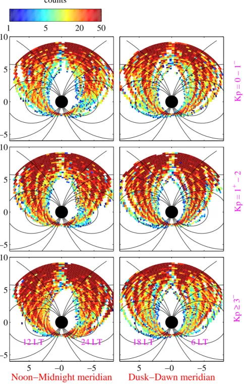
3.1 Meridional electron density distributions
Average electron density distributions are displayed in two meridional planes in Fig. 3a. The left panels are for the noon-midnight meridian, and the right panels are for the dusk-dawn meridian; the azimuthal extent of the sectors is ±1 h. The panels from top to bottom are for three different Kp lev-els: Kp= 0–1−(top panels), Kp =1+−2 (middle panels),
and Kp ≥ 3− (bottom panels), which correspond to mag-netically quiet, moderately active, and disturbed periods, re-spectively. The lines in each panel represent the dipole field lines at 65◦, 70◦, 75◦, and 80◦invariant latitude, or 5.6, 8.5, 14.9, and 32.3 L-shell. The color scale shown at the top of the figure is logarithmic and ranges from 0.2 to 100 cm−3.
The selected three Kpranges have approximately an equal amount of data (the number of data points, each of which is a one-minute average, are approximately 424 000, 535 000, and 539 000 for Kp= 0–1−, Kp=1+−2, and Kp≥3−,
re-spectively). Similar displays showing the count distributions are presented in Fig. 3b. Since the number of active days is small, we have binned all of the data gathered for Kp ≥3− together. Most bins contain several tens of counts and each count is an average of about 200 1Vpsmeasurements for one
minute so that the statistics of Fig. 3a can be considered sat-isfactory.
When interpreting the results of Fig. 3a, one must no-tice that on some occasions the average density may not be a representative value. For instance, in a bin which is fre-quently near the plasmapause, one may detect densities from 0.1 cm−3 to a few 100 cm−3. An average density for this bin may well be something near 10 cm−3, which does not represent a typical density, since this concept is somewhat ill-defined in such cases (for more detail, see Sect. 4.3).
In the left panels of Fig. 3a, the cusp appears as a rela-tively dense plasma region near 80–82◦of invariant latitude near noon, and it tends to move equatorward with increas-ing Kp. The average density in the cusp is a few electrons per cm3, which is less than the average magnetosheath den-sity. Examination of individual cusp crossings (see Laakso et al., 2002) reveal that the cusp densities are often several 10 cm−3, whereas the densities in the adjacent boundary
lay-ers are one or two ordlay-ers of magnitude less. All bins near the cusp region contain values from the cusp and boundary layers, resulting in averages that are not more than a few elec-trons per cm3. Another reason for low average cusp densities is the motion of the cusp away from the noon sector during large IMF By values. Although the cusp certainly exists at
all Kplevels, it appears less distinctly in these average bins during disturbed intervals. The large variation in the cusp position during disturbed conditions likely spreads out the cusp signatures in the average picture (see also Palmroth et al., 2001).
5
−0
−5
−5
0
5
10
12 LT
24 LT
Noon−Midnight meridian
5
−0
−5
18 LT
6 LT
Dusk−Dawn meridian
Kp
≥
3
−−5
0
5
10
Kp = 1
+− 2
−5
0
5
10
Kp = 0 − 1
−0.2
1
10
100
Ne (cm
−3)
Polar EFI:
1 April 1996 31 Dec 1999
Fig. 3a. (a) Average electron density in two meridional planes (scales in RE):
left panels are for the noon-midnight meridian, and right panels are for the dusk-dawn meridian. The panels from top to bottom are for three different Kp levels: Kp= 0–1−, Kp =1+−2 and
Kp ≥3−. The lines in each panel
rep-resent dipole magnetic field lines at in-variant latitudes of 65◦, 70◦, 75◦, and 80◦. (b) Number of counts used for the calculation of the average densities.
The polar cap region, which maps into the lobes of the magnetotail, is very tenuous and appears as dark blue in Fig. 3a. The average densities are around 0.2 cm−3or less
above 4 RE. It is obvious that there is a significant altitude
dependence here, since the average density is more than an order of magnitude higher at 1 RE altitude (southern polar
cap) than at 4–8 RE altitude (northern polar cap). This is
discussed in more detail in Sect. 4.2. In addition, as will be discussed in Sect. 4.1, the seasonal dependence is very strong and dominates the density variation in the polar cap at any al-titude. Notice that in the left-hand panels the southern polar cap density is asymmetric about the magnetic pole so that lower densities are observed in the nighttime sector. This is because the Sun is not illuminating the nightside ionosphere
5
−0
−5
−5
0
5
10
12 LT
24 LT
Noon−Midnight meridian
5
−0
−5
18 LT
6 LT
Dusk−Dawn meridian
Kp
≥
3
−−5
0
5
10
Kp = 1
+− 2
−5
0
5
10
Kp = 0 − 1
−1
5
20
50
counts
Polar EFI: 1 April 1996 31 Dec 1999
Fig. 3b. continued . . ..
in the polar cap. Finally, it seems that the low-altitude (south-ern) polar cap density may increase with Kp; this will also be investigated in more quantitative detail in Sect. 4.1.
When average plasma densities for the same L-shells are compared between the dayside and nightside, it seems as if the densities are higher on the dayside than on the nightside. In particular, the average densities between the plasmapause
and the magnetopause (between 65◦and 75◦in invariant lat-itude) can be quite high, up to 10 cm−3on the dayside and dawnside, whereas in the dusk and midnight sectors the av-erage densities on the same L-shells are lower. This is inves-tigated in more detail in the companion paper (Laakso et al., 2002).
ap-5
0
5
5
0
5
Counts
Kp
≥
3
-5
0
5
Ne distribution
5
0
5
Kp = 1
+2
5
0
5
Kp = 0 1
-1 20 50 100log(Counts)
2 10 50 100log(N
e) per cc
Polar satellite: 1 Apr 1996 31 Dec 1999
12 6 18 0 – – –
Fig. 4. Right panels: Average electron density distributions (scales in RE) in the inner magnetosphere mapped to the magnetic equator (i.e. within L = 9). The panels from top to bottom repre-sent three different Kplevels (same as in Fig. 3). The circles in each panel show the equatorial distances of L = 4 and 6. Left panels: Number of counts used for the calculation of the average densities.
proximately at the edge of a dark red color which corre-sponds to a density of about 100 cm−3. Not only is the den-sity decline at the plasmapause sharpest near midnight, but also the plasmapause location correlates most clearly with
Kp at midnight and dawn, implying that the dependence of the earthward motion of the plasmapause on Kpis strongest. The right-hand panels in Fig. 3a show a clear asymmetry between the dawnside and duskside plasmapause, as shown by numerous previous studies (e.g. Carpenter et al., 1993; Lemaire and Gringauz, 1998; Laakso and Jarva, 2001). The statistical results presented here demonstrate that the
asymmetry increases with increasing Kp, presumably due to strong motion of the dawnside plasmapause.
3.2 Equatorial electron density distributions
The right-hand panels of Fig. 4 present the average electron densities which have been mapped to the magnetic equator within the inner magnetosphere to L = 9; the number of counts in each bin is shown in the left panels. Our knowledge about the electron density distribution along a magnetic field line is quite poor and thus, the mapping of the density along
a field line is difficult to perform in general. However, over the Northern Hemisphere for L ≤ 9, the satellite is always located at high altitudes and low magnetic latitudes, being quite close to the magnetic equator; for instance, the L = 9 field line is crossed at 40◦or less of magnetic latitude over the Northern Hemisphere. For comparison, over the South-ern Hemisphere, the plasmapause is always crossed at low altitudes and high magnetic latitudes (see Fig. 1). For an in-compressible plasma, the density should be proportional to the cross section of the flux tube in which the plasma is lo-cated. For the magnetic latitude range 0–40◦at L = 4–9, this cross section does not change much, although for detailed modeling analysis it should be taken into account. Since the density is thus not expected to change very much between the measurement point and the equator, the electron density may be assumed constant along the magnetic field lines. How-ever, only measurements from the Northern Hemisphere are used here in order to avoid problems in mapping from the Southern Hemisphere.
The mapping is based on a dipole field model, which is ac-ceptable in the inner magnetosphere, although this assump-tion is less reliable during disturbed condiassump-tions. As in Fig. 3a, the panels from top to bottom in Fig. 4 are for three different
Kplevels: Kp= 0–1−, Kp=1+−2, and Kp≥3−. In each
panel, the circles are at 4 and 6 RE, the Sun is to the left, the
magnetotail to the right, the dawnside upward and the dusk-side downward. The color scale is logarithmic, as in Fig. 3a, representing densities ranging from 0.2 to 100 cm−3.
The data in Fig. 4 suggests that the steady-state plasma-pause moves earthward with increasing Kp. This effect is most pronounced on the nightside and is likely due to the effect of the increasing convection electric field during disturbed conditions. The duskside plasmaspheric bulge, discussed by several authors (Carpenter et al., 1993; Gal-lagher et al., 1995) and caused by the cancellation of coro-tational electric fields by convection electric fields (Lyons and Williams, 1984; Lemaire and Gringauz, 1998), is par-ticularly clear for high Kp. An interesting feature in Fig. 4 is the appearance of a dense region pointing from the plas-masphere toward the magnetopause in the 12–15 MLT sec-tor, which may be related to detached plasmaspheric material that is transported toward the dayside magnetopause (Kurita and Hasegawa, 1985).
One must bear in mind that the plasmasphere can experi-ence drastic changes during disturbed intervals, and in these cases the statistical pictures, such as those shown in Fig. 4, do not represent the plasmasphere well at all. For instance, Fig. 4 suggests that the position of the duskside plasmapause does not change much with Kp. However, from previous studies (Carpenter et al., 1993; Gallagher et al., 1995) we know that the plasmaspheric bulge is a very dynamic region, with strong erosion during high geomagnetic activity. Thus, this is an example of how average distributions or patterns, such as that shown in of Figs. 3a and 4, can be misleading if used for studying the behavior of dynamic regions, such as the plasmaspheric bulge.
4 Discussion
We have used forty-five months of spacecraft potential mea-surements collected by the electric field double probe on the Polar satellite to reveal electron density variations in the magnetosphere and to show how these depend on geomag-netic activity and season. Even though the observations are binned by Kp, the highly averaged density distributions yield static pictures, and the conclusions made from such plots must be taken with caution. Therefore, observations from individual orbits have been used to check the validity of the average patterns; the results are presented by Laakso et al. (2002) in the second part of this study.
Next we will discuss a few issues in more detail from a statistical point of view. First, Fig. 3a suggests that the po-lar cap plasma density varies with geomagnetic activity, and, therefore, in Sect. 4.1, we examine both the seasonal and geomagnetic dependence of the polar cap density. Second, also according to Fig. 3a, the polar cap density appears to be quite different at low (southern) and high (northern) altitudes. Combining the measurements from both hemispheres, the data points provide good altitude coverage, and we present a simple model on the altitude variation of the electron density in Sect. 4.2. Finally, based upon the data set of Fig. 4, we can investigate the local time variation of the average den-sity at any distance or L-shell. In Sect. 4.3 we particularly concentrate on the local time variation of the average density at the geosynchronous distance under different geomagnetic conditions.
4.1 Seasonal variation of the polar cap density
The polar cap plasma density is affected primarily by the Sun illuminating the polar ionosphere, which directly causes a significant seasonal variation of the polar cap density. We now investigate this variation by averaging all observations when the invarant latitude of the satellite is greater than 82◦ (or L>50) for both the Southern Hemisphere and the North-ern Hemisphere; this criterion was adopted in order to avoid the contributions from the cusp and the auroral oval on the average densities. We have also binned the data into three
Kpranges: Kp= 0–1 (quiet periods), Kp= 1+−2+ (mod-erate disturbances), and Kp ≥ 4−(strong disturbances), in order to separate the effect of geomagnetic activity on the polar cap density. The results are presented in Fig. 5. The upper panel is for the northern, high-altitude polar cap, and the lower panel is for the southern, low-altitude polar cap. An upper limit of the density of 300 cm−3was taken for the
calculation of the average. For the low-altitude summer po-lar cap, where very high densities, exceeding 300 cm−3, can occur (Laakso et al., 2002), the values shown in Fig. 5 can, therefore, be somewhat underestimated. This figure shows that at small distances (∼2 RE), the average density varies
between 1 cm−3for dark conditions and 100 cm−3for sunlit conditions, whereas at higher distances (5–9 RE) the
ampli-tude of the density variation between the two regions is typ-ically much less, being in the range of 0.03–0.3 cm−3. So,
2 4 6 8
0.1
2 4 6 81
N
e
(cm
–3)
Kp 4– – 9 1+ – 2+ 0 – 1 northern hemisphere high-altitude polar cap1
10
100
N
e
(cm
–3)
1996 1997 1998 1999
Jul Jan Jul Jan Jul Jan Jul
southern hemispherelow-altitude polar cap
Fig. 5. The monthly averages of the electron density in the polar cap region over the Southern Hemisphere (upper panel) and the Northern Hemisphere (lower panel). The measurements in different geomagnetic conditions are separated: solid lines are for quiet con-ditions, dotted lines for moderately ac-tive conditions, and dashed lines for dis-turbed conditions. Note the different density scales between the two panels.
the low-altitude polar cap density increases by one or two or-ders of magnitude from winter to summer, whereas the high-altitude density increases only by a factor of 2–10 between these seasons.
These densities are in the same range as those observed by Persoon et al. (1983) using DE-1 measurements. They obtained an average density of 30 cm−3at 2 REdistance and
1 cm−3at 4.5 REdistance; however, they averaged all data at
L greater than 10 (71◦of invariant latitude) from September
to February over the Northern Hemisphere.
Geomagnetic activity also affects the polar cap density. In summer, the average density in the low-altitude polar cap in-creases by a factor of 2–10 during high Kp, while in win-ter months (May–August, for the Southern Hemisphere) the density may increase one or two orders of magnitude. Of course, for an individual event, the density enhancement can even be much more dramatic. At high altitudes (northern po-lar cap data), the variation of the average density with mag-netic activity is also clear, with density increases of a factor of 2–5 during high Kp, but this factor appears to be quite in-dependent of season, contrary to low-altitude observations. We speculate that during high Kpthe low-altitude polar cap is readily filled by heavy ionospheric ions that are gravita-tionally bound and cannot escape to the high altitudes.
4.2 Altitude variation of the polar cap density
To study the altitude variation of the polar cap density, the measurements must be collected during the same season and also under similar geomagnetic conditions. For example, when comparing similar seasons and magnetic activity pe-riods shown in Fig. 5, it is clear that in the winter the density decreases by a factor of 10–20 from low to high altitudes, whereas in the summer the decline is typically much steeper, of the order of 200–1000.
We now investigate one case in more detail. Figure 6 presents the polar cap density versus altitude for dark con-ditions (December–January for the Northern Hemisphere, and June-July for the southern one) during very quiet inter-vals (Kp = 0–0+). In order to decrease the scatter of data points, the measurements over the Northern Hemisphere are averaged over 20 min, whereas the data from the Southern Hemisphere near 2 RE are one-minute averages. The figure
presents two reference lines: the dashed line, proportional to distance as r−3, represents the field-aligned outflow with a constant flow velocity, whereas the solid line, r−4.4, shows the best fit to the data points below 7 REdistance; for
refer-ence, using DE-1 data, Persoon et al. (1983) obtained a radial dependence of r−3.8. Thus, the Polar data suggest that the plasma particles are accelerated as r1.4with distance, which
0.01
0.1
1
10
100
N
e(cm
-3)
Altitude (R
E)
2 3 4 5 6 7 8 9
winter
Kp = 0 - 0
+Fig. 6. Polar cap density against alti-tude for dark hemispheres during very quiet intervals (Kp = 0–0+). The dashed line, proportional to distance as r−3, represents the radial outflow with constant flow velocity, and the solid line, r−4.4, is the best fit to the data points below 7 REdistance.
3 4 5 6 1 2 3 4 5 6 10 2 3 4 Ne (cm –3 ) 18 12 6 0
magnetic local time Kp
0 – 1– 1+ – 2 3– – 9
Fig. 7. Average electron densities at L = 6.6 plotted against magnetic local time, based on 45 months of Polar data over the Northern Hemisphere. Densi-ties are binned with the Kpindex as in Fig. 4.
is somewhat faster than observed by DE-1. When observa-tions during higher Kpranges are examined, a similar result is obtained. A more complete analysis on this subject is pre-sented by Laakso and Grard (2002).
Above 7 RE, the data points seem to form a flat
distribu-tion, likely because the magnetic field model is not dipolar at high altitudes but also because at these distances the space-craft may be immersed in the high-latitude boundary layer and the cusp rather than in the polar cap. This is in accor-dance with the observations of Palmroth et al. (2001), which indicate that above 7 RE distance the cusp may spread out
over a large spatial volume.
4.3 Plasma distributions at geosynchronous distance (L = 6.6)
Using the average densities of Fig. 4, we now study the local time variation of the average density near L = 6.6, which cor-responds to the geosynchronous distance at the equator. The results are shown in Fig. 7 where the dashed line gives the
average density for the quiet periods, the dotted line for the moderate disturbances, and the solid line for the disturbed conditions. This figure shows that the density at geosynchro-nous orbit tends to decrease with increasing Kp at all sec-tors except the bulge sector (14–17 MLT). Particularly large density changes appear in the pre-midnight sector, where the density gradient from 18 MLT to 23 MLT becomes steeper with increasing Kpand moves sunward. This is the region that is most strongly affected by geomagnetic disturbances. In the post-midnight sector, the densities can also vary signif-icantly, due to a strong radial motion of the plasmapause (see Fig. 4). Large density variations in this sector can occur par-ticularly during quiet periods, which can be associated with the expansion of the plasmasphere, with the detachments of plasmaspheric plasma (Chappell, 1974), or with plume-type plasmaspheric structures (Ober et al., 1997). The interpreta-tion of the average values shown in Fig. 4 must be carried out with caution since the average values are not necessarily well-defined variables in a region where the density can have a wide range of values. This applies particularly to the
geo-25 0 probability (%) Ne ≥ 100 cm–3 Kp: 0 –1 1+ – 2+ 3– – 9 100 75 50 25 0 probability (%) Ne = 10 – 100 cm–3 100 75 50 25 0 probability (%) Ne = 1 – 10 cm–3 100 75 50 25 0 probability (%) Ne = 0.1 – 1 cm–3 3 2 1 0 probability (%) 24 18 12 6 0 MLT Ne < 0.1 cm–3
Fig. 8. Probabilities of detecting different density regimes at the geosynchronous distance as function of MLT. Three Kpranges are used: quiet periods (solid lines), weak disturbances (dotted lines), and strong disturbances (dashed lines). This figure uses data of Fig. 4.
stationary orbit that can often be in the plasmasphere, trough, or plasma sheet.
The data in Fig. 7 clearly shows that the average den-sity increases an order of magnitude from the nightside to the dayside: the average density varies in the range of 0.6– 30 cm−3for quiet intervals and in the range of 0.4–10 cm−3 for disturbed intervals; the low values correspond to a typical trough density and the high values to a typical plasmaspheric density at L = 6.6. As discussed above, the average values may not always be well-defined variables in this region, but
nevertheless these results agree surprisingly well with daily variations reported by Higel and Wu (1984) (see their Fig. 2). We continue our investigation by showing the probabil-ities of detecting different density regimes at the geosyn-chronous distance as a function of magnetic local time and
Kp(Fig. 8). Very low densities (i.e. below 0.1 cm−3), pos-sibly representing the encounters of auroral cavities or the lobes, are observed at geostationary orbit approximately 2% of the time around local midnight, but hardly ever in the 05– 18 MLT sector. Due to a low number of events, a possible
Table 1a. Occurrence probabilities (%) of plasma regions at L = 6.6 for Kp= 0–1 MLT: 00–06 06–12 12–18 18–24 plasma sheet 23 4 0 11 trough 44 45 27 33 plasmasphere (normal) 30 39 62 48 plasmasphere (dense) 3 12 11 8
Table 1b. As Table 1a, but for Kp= 1+−2+
MLT: 00–06 06–12 12–18 18–24
plasma sheet 22 4 0 31
trough 70 62 36 33
plasmasphere (normal) 7 28 52 29
plasmasphere (dense) 1 6 12 7
Table 1c. As Table 1a, but for Kp= 3 − 9
MLT: 00–06 06–12 12–18 18–24
plasma sheet 19 2 3 45
trough 73 79 44 37
plasmasphere (normal) 8 16 43 15
plasmasphere (dense) 0 3 10 3
Kpdependence cannot be resolved. The results for the other density regimes are summarized in Tables 1a–c for four MLT sectors. Based on the local time occurrence of the observed density distributions, we can divide the measurements into the following general groups: the density range >100 cm−3 represents the dense plasmasphere (saturated flux tubes), the range 10–100 cm−3represents the normal plasmasphere, the range 1–10 cm−3represents the trough, and the range 0.1– 1 cm−3represents the plasma sheet. This is a rough classifi-cation since, for instance, in the plasma sheet the density may exceed 1 cm−3during magnetically active periods. This ex-ercise should preferably be taken as an examination of what densities are typically encountered at geostationary orbit at different MLT sectors.
Based on the observed distributions, the plasma sheet is encountered quite often except for the 11–15 MLT sector. The probability of observing the plasma sheet correlates strongly with Kpin the pre-midnight sector, whereas in the post-midnight sector the probability is approximately 25%, with no significant Kpdependence.
The top two panels in Fig. 8 can be used to predict how often the plasmapause extends beyond geosynchronous dis-tance. The normal plasmaspheric densities (10–100 cm−3)
are encountered frequently at all MLT, between a 30% prob-ability near midnight and a 60% probprob-ability in the noon-dusk sector for low Kp; the highest probability of 70% ap-pears near 16 MLT. Notice that the probability is roughly constant with MLT for a low Kp, whereas for a higher Kpthe probability has a strong MLT dependence. This is in accor-dance with the data shown in Fig. 4 which indicates that the plasmasphere moves earthward and becomes more asymmet-ric with increasing Kp. Notice that the dense plasmasphere (>100 cm−3) is observed at the geostationary distance only 10–15% of the time, except around 24 MLT, where the prob-ability is almost zero. Such densities can be detected during intervals where the flux tubes have reached their saturation levels (Lawrence et al., 1999).
The trough is very commonly observed at 00–11 MLT with a clear Kpdependence. On the other hand, in the dusk sec-tor, the probability of encountering the trough shows no Kp dependence, yet it increases towards midnight. In general, the probability of observing the trough appears to evolve in-versely to that of the normal plasmapause.
5 Summary
Spacecraft potential measurements gathered with the Polar electric field instrument have been used to study the distribu-tion of the electron density and its variadistribu-tions in the magneto-sphere between 2–9 REgeocentric distances. This technique
provides a measure of the thermal plasma density to values even below 0.1 cm−3with high time resolution (e.g. less than 0.1 s).
Using this approach, global average densities were pro-vided where signatures of the polar cap, cusp, and plasma-pause are readily apparent, as well as their dependence on magnetic activity and season. Detailed studies of each area promise to elucidate many of the processes affecting the plasma distributions in these regions, particularly when an-alyzed in conjunction with electric and magnetic fields and particle data.
The major findings of the present study are:
(1) The density in the polar cap behaves systematically with season. At low altitudes (∼1 RE), the average density
is approximately 100 cm−3 in summer and 1 cm−3 in winter. At high altitudes (4–8 RE), the density varies
similarly with season between 0.03–0.3 cm−3. In fact, the polar cap density depends particularly upon whether or not the Sun is illuminating the footpoint region in the ionosphere.
(2) The geomagnetic effects are very important for the po-lar cap density: during high Kp (≥ 4−), the average density increases one or two orders of magnitude com-pared to the quiet-time level (Kp <1). For individual events, corresponding to high magnetic activity, density enhancements can be much larger. The average winter-time density for high Kpcan easily exceed the average summertime density for low Kp.
(3) The polar cap density declines quite steeply with alti-tude: in winter the density decreases by a factor of 10– 20 from 2 to 4–8 REaltitudes. In summer, the decline is
much stronger, of the order of 200–1000, over the same altitude range. A detailed analysis for quiet intervals in winter suggests that the density varies with altitude as
r−4.4, implying that the ionospheric plasma is acceler-ated with distance as r1.4.
(4) The cusp plasma density and location can significantly change from orbit to orbit. The average cusp is 1–2◦ wide and centered at 80–82◦ for quiet intervals, and moves equatorward for increasing Kp. For high Kp, the cusp disappears in the average pictures to be likely due to a large spread of the cusp location under disturbed conditions.
(5) Analysis of the densities near L = 6.6 shows that the av-erage density obtained here is in good accordance with daily variations reported by Higel and Wu (1984). In ad-dition, we found that the average density decreases with increasing Kp at all MLT sectors, except 14–17 MLT. The large density values in this sector are possibly main-tained by the rotation of the bulge toward the Sun or de-tached plasma elements eroded from the bulge region. (6) The electron density distribution at L = 6.6 indicates
that the dense plasmasphere (>100 cm−3) is detected 0–15% of the time, depending on MLT and Kp. The normal plasmasphere (10–100 cm−3) is detected quite frequently, with a strong dependence on MLT and Kp. As an example, for Kp= 0–1, the probability is 30–60%, depending on MLT, while the probability is only 10– 40% for Kp ≥3−. The trough (1–10 cm−3) is
encoun-tered as frequently as the normal plasmasphere, but the probability evolves with MLT and Kpinversely to that of the normal plasmapause. The highest probabilities for detecting the trough are 65–80% at 00–11 MLT for high Kp. Low densities (0.1–1 cm−3), related to plasma sheet encounters, are detected most likely in the 18– 24 MLT sector, with probabilities increasing with Kp. For high Kp, the plasma sheet is encountered approxi-mately 50% of the time. At 00–06 MLT, the probability is 20%, with no apparent Kpdependence.
Acknowledgements. This work is supported under NASA grant
NAG5-3182.
Topical Editor G. Chanteur thanks G. Marklund and V. Pierrara for their help in evaluating this paper.
References
Carpenter, D. L., Giles, B. G., Chappell, C. R., Decreau, P. M. E., Anderson, R. R., Persoon, A. M., Smith, A. J., Corcuff, Y., and Canu, P.: Plasmasphere dynamics in the duskside bulge sector: a new look at an old topic, J. Geophys. Res., 98, 19 243–19 271, 1993.
Chappell, C. R.: Detached plasma regions in the magnetosphere, J. Geophys. Res., 79, 1861–1870, 1974.
Escoubet, C. P., Pedersen, A., Schmidt, R., and Lindqvist, P. A.: Density in the magnetosphere inferred from ISEE-1 spacecraft potential, J. Geophys. Res., 102, 17 595–17 609, 1997.
Gallagher, D. L., Craven, P. D., Comfort, R. H., and Moore, T. E.: On the azimuthal variation of core plasma in the equatorial mag-netosphere, J. Geophys. Res., 100, 23 597–23 605, 1995. Harvey, P., Mozer, F. S., Pankow, D., Wygant, J., Maynard, N. C.,
Singer, H., Sullivan, W., Anderson, P. B., Pfaff, R., Aggson, T., Pedersen, A., Falthammar, C.-G., and Tanskanen, P.: The electric field instrument on the Polar satellite, Space Sci. Rev., 71, 583– 596, 1995.
Higel, B. and Wu Lei: Electron density and plasmapause charac-teristics at 6.6 Re: a statistical study of the GEOS 2 relaxation sounder data, J. Geophys. Res., 89, 1583–1601, 1984.
Johnson, M. T., Wygant, J. R., Cattell, C., Mozer, F. S., Temerin, M., and Scudder, J.: Observations of the seasonal dependence of the thermal plasma density in the Southern Hemisphere auroral zone and polar cap at 1 Re, J. Geophys. Res., 106, 19 023–19 033, 2001.
Kurita, K. and Hasegawa, M.: Evaluation of the effectiveness of the-oretical model calculation in determining the plasmapause struc-ture, J. Geophys., 57, 103, 1985.
Laakso, H. and Grard, R.: The electron density distribution in the polar cap: its variability with seasons, and its response to mag-netic activity, in: Space Weather Study Using Multipoint Tech-niques, (Ed) Lyu, L.-H., Proceedings of COSPAR Colloquium 12, Pergamon, 193–202, 2002.
Laakso, H. and Jarva, M.: Position and motion of the plasmapause, J. Atmos. Terr. Sol. Phys., 63, 1171–1178, 2001.
Laakso, H. and Pedersen, A.: Ambient electron density derived from differential potential measurements, in: Measurement Techniques in Space Plasmas, (Eds) Borovsky, J., Pfaff, R., and Young, D., AGU Monograph 102, AGU, Washington, DC, 49– 54, 1998.
Laakso, H., Opgenoorth, H., Wygant, J., Escoubet, P., Clemmons, J., Johnson, M., Maynard, N., Mozer, F., Pfaff, R., and Scud-der, J.: Electron Density Distribution in the Magnetosphere, in: Correlated Phenomena at the Sun, in the Heliosphere and in Geospace, ESA SP-15, ESA, Noordwijk, The Netherlands, 53– 58, 1997.
Laakso, H., Pfaff, R., and Janhunen, P.: Polar observations of elec-tron density distribution in the Earths magnetosphere. 2. Density profiles, Ann. Geophysicae, this issue, 2002.
Lawrence, D. J., Thomsen, M. F., Borovsky, J. E., and McComas, D. J.: Measurements of early and late time plasmasphere refilling as observed from geosynchronous orbit, J. Geophys. Res., 104, 14 691–14 704, 1999.
Lemaire, J. F. and K. I. Gringauz, The Earth’s Plasmasphere, Cam-bridge Univ. Press, CamCam-bridge, 1998.
Lyons L. R. and Williams, D. J.: Quantitative Aspects of Magneto-spheric Physics, D. Reidel, Dordrecht, 1984.
Marklund, G. T., Blomberg, L. G., Falthamma, C.-G., Erlandson, R. E., and Potemra, T. A.: Signatures of the high-altitude polar cusp and dayside auroral regions as seen by the Viking electric field experiment, J. Geophys. Res., 95, 5767–5780, 1990. Moore, T. E. and Delcourt, D. C.: The geopause, Rev. Geophys.,
33, 175–209, 1995.
Moore, T. E., Chappell, C. R., Chandler, M. O., Fields, S. A., Pol-lock, C. J., Reasoner, D. L., Young, D. T., Burch, J. L., Eaker, N., Waite, J. H., McComas, D. J., Norholt, J. E.,Thomsen, M. F., Berthelier, J. J., and Robson, R.: The thermal ion dynamics ex-periment and plasma source instrument, Space Sci. Rev., 71, 409,
1995.
Mozer, F. S., Torbert, R. B., Fahleson, U. V., F˝althammar, C.-G., Gonfalone, A., and Pedersen, A.: Electric field measurements in the solar wind, bow shock, magnetosheath, magnetopause, and magnetosphere, Space Sci. Rev., 22, 791–804, 1978.
Ober, D. M., Horwitz, J. L., Thomsen, M. F., Elphic, R. C., Mc-Comas, D. J., Belian, R. D., and Moldwin, M. B.: Premidnight plasmaspheric “plumes”, J. Geophys. Res., 102, 11 325–11 334, 1997.
Palmroth, M., Laakso, H., and Pulkkinen, T.: Location of high-altitude cusp during steady solar wind conditions, J. Geophys. Res., 106, 21 109–21 122, 2001.
Pedersen, A.: Solar wind and magnetosphere plasma diagnostics by spacecraft electrostatic potential measurements, Ann. Geophysi-cae, 13, 118–129, 1995.
Pedersen, A., Grard, R., Knott, K., Jones, D., Gonfalone, A., and Fahleson, U.: Measurements of quasistatic electric fields be-tween 3 and 7 Earth radii on GEOS-1, Space Sci. Rev., 22, 333– 346, 1978.
Pedersen, A., Cattell, C. A., F˝althammar, C.-G., Formisano, V., Lindqvist, P.-A., Mozer, F., and Torbert, R.: Quasistatic electric field measurements with spherical double probes on the GEOS and ISEE satellites, Space Sci. Rev., 37, 269–312, 1984. Persoon, A. M., Gurnett, D. A., and Shawhan, S. D.: Polar cap
elec-tron densities from DE 1 plasma wave observations, J. Geophys. Res., 88, 10 123–10 136, 1983.
Rosenbauer, H., Gr˝unwaldt, H., Montgomery, M. D., Paschmann, G., and Sckopke, N.: Heos 2 observations in the distant polar magnetosphere: the plasma mantle, J. Geophys. Res., 80, 2723– 2737, 1975.
Scudder, J. D., Cao, X., and Mozer, F. S.: The photoemission cur-rent – spacecraft potential relation: Key to routine, quantita-tive low-energy plasma measurements, J. Geophys. Res., 105, 21 281–21 294, 2000.
Tsyganenko, N. A. and Stern, D. P.: Modeling the global magnetic field of the large-scale Birkeland current systems J. Geophys. Res., 101, 27 187–27 198, 1996.