RUGC 2020 AJCE, vol. 38 (1)
117
Finite Element Modeling of the Mechanical Behavior of
Earth Concrete
Hassan Fardoun1, Jacqueline Saliba1, Nadia Saiyouri1
1 Université de Bordeaux, UMR 5295, Institut de Mécanique et d’Ingénierie (I2M), CNRS, Esplanade des Arts et Métiers, 33405 Talence, France.
RESUMEWith the increased awareness of environmental issues, research on earth concrete as an alternative construction material has gained a renewed interest. Compared to conventional concrete, this material is less resistant and hence better knowledge of the mechanical behavior is required. In the present paper, the mechanical response of earth concrete is assessed. Finite elements simulations are performed at the macroscopic scale using Fichant's isotropic damage model in order to have a better understanding of the fracture behavior of these materials and to determine their mechanical properties. The capability of the model is valued by comparing the results of the numerical simulations with the corresponding experimental ones. The results reveal the ability of this damage model to successfully describe the mechanical behavior and performance of earth concrete materials.
Mots-clefs Earth concrete, Finite element analysis, Damage, Mechanical behavior
I. INTRODUCTION
The fast growing of the construction industry is proportionally and heavily accompanied with environmental and energetic issues. With the increased awareness, an obvious trend towards alternative materials is highly noticed in the civil engineering research. Earth concrete is being considered as a promising alternative. It possesses advantages in terms of energy consumption, cost, recyclability, and CO2 emissions.
Compared to conventional concrete, this material is less resistant and hence better knowledge of the mechanical behavior is required. Unlike experiments, few numerical studies have been performed (Nowamooz & Chazallon, 2011; Miccol & al., 2015). In addition, few studies have been conducted on the tensile strength of earth concrete even though it is an important parameter especially in extreme conditions due to thermal, hydric, or seismic loadings... Note that, earth concrete is very sensitive to water which may affect its durability and mechanical properties in terms of strength and deformability and therefore a hygromechanical coupling should be considered.
This work aims to assess numerically the mechanical behavior of earth concrete under compressive and flexural loading based on experimental results. Finite element analysis has been conducted. The nonlinear behavior of earth concrete has been taking into account using a continuum damage model. Thus, the physical processes of microcracking, nucleation and void growth are replaced by state variables that act on the stiffness tensor of materials. In addition, the irreversible deformations have been also considered using plasticity.
RUGC 2020 AJCE, vol. 38 (1)
118
II. DAMAGE MODEL A. Constitutive equations
Fichant’s damage model has been adopted (Saliba & al, 1996). This model is implemented in the finite element software Cast3m. It is an extension of Mazars model taking into account the unilateral effect and plasticity. It is based on the relationship between effective stress 𝜎̃(𝑦) and total stress 𝜎(𝑦):
𝜎(𝑦): = (1 − 𝑑)𝜎̃(y) (1)
The damage variable (d) is a scalar function ranging from 0 for undamaged material to 1 for a completely damaged one. The evolution of damage is as follows:
𝑑 = 1 −𝜀𝑑0
𝜀𝑒𝑞
𝑒[𝐵𝑡(𝜀𝑑0−𝜀𝑒𝑞)] (2)
where 𝐵𝑡 presents the softening strain behavior, 𝜀𝑑0= 𝑓𝑡
𝐸 corresponds to the initial damage
threshold (𝐸 being the elastic modulus and 𝑓𝑡 the tensile strength) and 𝜀𝑒𝑞 the equivalent strain:
𝜀𝑒𝑞 = √∑ < 𝜀𝑖>2 3
𝑖=1
(3)
where < εi > represents the positive side of εi of the strain tensor. The complete fracture energy is expressed as follows:
𝐺𝑓 ℎ = 𝑓𝑡𝜀𝑑0 2 + 𝑓𝑡 𝐵𝑡 (4) For plasticity, the Nadai yield function is a combination of two Drucker-Prager functions (F1 and F2) with the same hardening evolution. The expression is as follows:
𝐹𝑖= √
2 3𝐽2𝑡+ 𝐴𝑖
𝐼1𝑡
3− 𝐵𝑖𝑤 (5)
where 𝐼1𝑡 is the first invariant of the effective stress, 𝐽2𝑡 the second invariant of the second
deviatoric effective stress, 𝐴𝑖and 𝐵𝑖 are four parameters linked to the ratios of tensile strength to
the compressive strength and the biaxial compressive strength to the uniaxial tensile strength. B. Application on earth concrete at macroscale
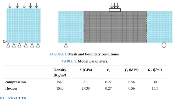
Numerical simulations are conducted to simulate the fracture behavior of earth concrete obtained by Kouta & al. (2019); where compressive tests were performed on 10x10x10 cm3 specimens and flexural tests on 28x7x7 cm3 unnotched beams with an effective span of 25 cm. Numerical simulations are conducted at a macroscale under plane stress condition. Quadrilateral (QUA4) elements with four Gaussian points are considered. For compressive tests, an imposed displacement load is designed at the top while an incremental vertical displacement of a rigid plate is considered as loading acting at the top middle side for flexural simulation. Figure 1 shows the finite element meshes and boundary conditions of both tests. In order to localize damage, a spatial variability has been considered for the mechanical properties using the Turning Bands Method that creates a spatially correlated random property field (Saliba et al., 2016). Table 1
RUGC 2020 AJCE, vol. 38 (1)
119 presents the parameters used for the simulations. Tensile strength, density and elastic modulus have been determined based on experimental results. The fracture energy, defined as the energy required to create a unit area of cracking surface, has been also measured. For the compressive tests, it was calculated based on the area under the stress strain curves. However, for the flexure tests, it was determined based on the load-deflection curves obtained experimentally. It is equal to the ratio of the work dissipated in the area under the load-deflection curve (WF [N.m]) to the area of the uncracked ligament (Alig [m²]). Note that the obtained fracture energy values are lower than that of normal concrete due to the much lower compressive strength of earth concrete.
FIGURE 1. Mesh and boundary conditions.
TABLE 1: Model parameters.
Density (Kg/m2) 𝑬 (GPa) 𝝂𝟎 𝒇𝒕 (MPa) 𝑮𝒇 (J/m2) compression 1540 3.1 0.27 0.56 30 flexion 1540 2.038 0.27 0.56 15.1 III. RESULTS
Figure 2 shows the numerical and experimental results. The comparison of numerical and experimental stress- strain curves for compressive tests and Load-CMOD curves for flexure tests reveals a successful behavior description. It can be stated that the reproducing of the mechanical behavior is well performed in both tests. The concrete is under elastic stage at the beginning then the nonlinearity begins earlier under compression with stable distributed microcracks before the macro - crack propagation stage in the post peak region. The macrocrack propagates in an unstable way under flexure tests, however a multi cracking has been observed under compression. This multi cracking due to shear stress in addition to the friction and the crushing of concrete due to the low slenderness ratio of the specimen induce a higher fracture energy dissipation under compression.
The damage fields are also presented for compressive and flexural tests (figure 3). The failure patterns show a correct description of the fracture process in comparison with the experiments for each test. A shear failure is observed when concrete is subjected to uniaxial compression due to concrete expansion and condition limits. A thin crack path is reported in flexion which can be attributed to the brittle behavior of earth concrete in flexion. Note that, as the beam is unnotched, additional energy was required for the crack initiation with several damage initiations in the bottom before the macrocracking propagation along the ligament length of the beam.
RUGC 2020 AJCE, vol. 38 (1)
120
FIGURE 2. Comparison of numerical and experimental stress- strain curves for compressive tests and
Load-CMOD curves for flexure tests.
FIGURE 3. Damage fields obtained at the end of the compressive and flexural simulations.
IV. CONCLUSION
The compressive and flexural behaviors of earth concrete have been studied in this paper. The results show that Fichant’s damage model is capable of describing the mechanical performance of earth concrete at the macroscopic scale. Additional work will be realized in the future in order to calibrate the plasticity parameters based on loading / unloading compressive tests and to take into account the hygroscopic effect on the mechanical properties and the long term behavior considering creep and shrinkage deformation.
REFERENCES
Miccol, L., Oliveira, D., Silva, R., Müller, U., Schueremans, L. (2015). Static behaviour of rammed earth: experimental testing and finite element modelling. Mater. Struct. 48, 3443–3456.
Nowamooz, H., Chazallon, C. (2011). Finite element modelling of a rammed earth wall. Constr. Build. Mater. 25, 2112–2121.
Saliba, J., Matallah, M., Loukili, A., Regoin, J.P., Grégoire, D., Verdon, L., Pijaudier-Cabot, G., (2016). Experimental and numerical analysis of crack evolution in concrete through acoustic emission technique and mesoscale modelling. Eng. Fract. Mech. 167, 123–137.
N. Kouta, J Saliba., B. El Olfi, & N. Saiyouri. (2019). Study of the effect of flax fibers on the fracture behavior of earth concrete by simultaneous application of digital image correlation and acoustic emission. FraMCoS-X, 23-26 June, Bayonne, France.