HAL Id: hal-00085140
https://hal.archives-ouvertes.fr/hal-00085140
Submitted on 11 Jul 2006
HAL is a multi-disciplinary open access
archive for the deposit and dissemination of
sci-entific research documents, whether they are
pub-lished or not. The documents may come from
teaching and research institutions in France or
abroad, or from public or private research centers.
L’archive ouverte pluridisciplinaire HAL, est
destinée au dépôt et à la diffusion de documents
scientifiques de niveau recherche, publiés ou non,
émanant des établissements d’enseignement et de
recherche français ou étrangers, des laboratoires
publics ou privés.
VSI: a milli-arcsec spectro-imager for the VLTI
Fabien Malbet, Pierre Kern, Jean-Philippe Berger, Laurent Jocou, Paulo
Garcia, David Buscher, Karine Rousselet-Perraut, Gerd Weigelt, Mario Gai,
Jean Surdej, et al.
To cite this version:
Fabien Malbet, Pierre Kern, Jean-Philippe Berger, Laurent Jocou, Paulo Garcia, et al.. VSI: a
milli-arcsec spectro-imager for the VLTI. Advances in Stellar Interferometry, 2006, Orlando, United States.
�hal-00085140�
ccsd-00085140, version 1 - 11 Jul 2006
VSI: a milli-arcsec spectro-imager for the VLTI
F. Malbet
a, P.Y. Kern
a, J.-P. Berger
a, L. Jocou
a, P. Garcia
b, D. Buscher
c, K.
Rousselet-Perraut
a, G. Weigelt
d, M. Gai
e, J. Surdej
f, J. Hron
g, R. Neuh¨auser
h, E. Le Coarer
a,
P.R. Labeye
i, J. Le Bouquin
a, M. Benisty
a, E. Herwats
a aLaboratoire d’Astrophysique de Grenoble (LAOG, France);
bCentro de Astrof´ısica da Universidade do Porto (CAUP, Portugal);
cCavendish Laboratory, University of Cambridge (United Kingdom);
dMax-Planck Institut f¨
ur Radioastronomie in Bonn (MPIfR, Germany);
e
Istituto Nazionale di Astrofisica - Osservatorio Astronomico di Torino (INAF-OATo, Italy);
fInstitut d’Astrophysique et de G´eophysique, Universit´e de Li`ege (IAGL, Belgium);
g
Institut f¨
ur Astronomie, Universit¨at Wien (IfA, Austria);
h
Astrophysikalisches Institut und Universit¨ats-Sternwarte (AIU Jena, Germany);
iCEA-LETI (France).
ABSTRACT
VLTi Spectro-Imager (VSI) is a proposition for a second generation VLTI instrument which is aimed at providing the ESO community with the capability of performing image synthesis at milli-arcsecond angular resolution. VSI provides the VLTI with an instrument able to combine 4 telescopes in a baseline version and optionally up to 6 telescopes in the near-infrared spectral domain with moderate to high spectral resolution. The instrument contains its own fringe tracker in order to relax the constraints onto the VLTI infrastructure. VSI will do imaging at the milli-arcsecond scale with spectral resolution of: a) the close environments of young stars probing the initial conditions for planet formation; b) the surfaces of stars; c) the environment of evolved stars, stellar remnants and stellar winds, and d) the central region of active galactic nuclei and supermassive black holes. The science cases allowed us to specify the astrophysical requirements of the instrument and to define the necessary studies of the science group for phase A.
Keywords: Instrumentation, optical interferometry, interferometers, infrared, imaging, spectroscopy
1. INTRODUCTION
VSI is proposed as second generation VLTI instrument providing the ESO community with the capability of performing image synthesis at milli-arcsecond angular resolution. Image synthesis is the standard operation of radio and (sub-)mm interferometers. VSI is the result of the merging of two previous concept studies, VITRUV1 and BOBCAT.2 They were previously presented at the ESO workshop in 2005. VSI provides the VLTI with an instrument able to combine 4 telescopes in a baseline version and optionally up to 6 telescopes in the near-infrared spectral domain with moderate to high spectral resolution. The instrument contains its own fringe tracker in order to relax the constraints onto the VLTI infrastructure.
A preliminary system analysis of VSI, allowed us to clarify the high level specifications of the system, the external constraints and to perform a functional analysis. In particular, the instrument was separated into 14 functions, the context of PRIMA was addressed and the system tasks for the required phase-A study were defined. Two solutions for the science beam combiner were identified one based on integrated optics and another on bulk optics. These two solutions are inherited from the two concepts merged. One of the goals of the Phase A study is to define which of them will be used by VSI. VSI has an internal fringe tracker which relaxes the constraints on the VLTI interfaces by allowing to servo optical path length differences of the input beams to the required level.
The paper describes the science cases, the preliminary system study and presents the possible concepts.
Further author information: (Send correspondence to F. Malbet) E-mail: fabien.malbet@obs.ujf-grenoble.fr
2. SCIENCE CASES
VSI concept is a general purpose instrument aimed at exploiting the full capability of the VLTI infrastructure including the faint science space enabled by PRIMA. VSI is up to 5 times faster than current interferometric instrumentation (AMBER) because it combines up to 6 telescopes. The wavelength range is JHK. Three spectral resolutions are available ∼100, ∼1000 and ∼10000. The dynamic range of the reconstructed images is 10-100 with a goal of 100-1000. There is a goal of retaining polarization information. The current science cases definition methodology was to concentrate in a few fields where VSI can make a substantial contribution, without being exhaustive.
2.1. The formation of stars and planets
The early evolution of stars and the initial conditions for planet formation are determined by the interplay of accretion and outflow processes. Due to the small spatial scales where these processes engines actuate, very little is known about the actual physical and chemical mechanisms at work. Interferometric imaging at 1 mas (milli-arcsecond) will directly probe the regions responsible for the bulk of continuum emission excess from these objects therefore constraining the currently highly degenerate models for the spectral energy distribution. In the emission lines a variety of processes will be probed, in particular outflow and accretion magnetospheres. The inner few AUs of evolved planetary systems will also be studied, providing additional information on their formation and evolution processes, as well as on the physics of extrasolar planets.
2.2. Imaging stellar surfaces
Optical imaging instruments are a powerful means to resolve stellar features at the generally patchy surfaces of stars throughout the HR diagram. Optical interferometry has already proved its ability to derive surface structure parameters such as limb darkening or other atmosphere parameters. VSI, as an imaging device, is of strong interest to study various specific features as vertical and horizontal temperature profiles, abundance inhomogeneities and detect their variability as the star rotates and pulsates. This will provide important keys to address stellar activity processes, mass-loss events, magneto-hydrodynamic mechanisms, pulsation and stellar evolution.
2.3. Evolved stars, stellar remnants and stellar winds
HST and ground-based observations revealed that the geometry of young and evolved PNe and related ob-jects (e.g. nebulae around symbiotic stars) show an incredible variety of elliptical, bi-polar, multi-polar, point-symmetrical, and highly collimated (including jets) structures. The proposed mechanisms explaining the ob-served geometries (disks, MHD collimation and binarity) can only be tested by interferometric imaging at 1 mas resolution.
Extreme cases of evolved stars are stellar black holes. In microquasars the stellar black-hole accretes mass from a donor. The interest of these systems lies in the small spatial scales and high multi-wavelength variability. Milli-arcsecond imaging in the NIR will allow to disentangle of dust from jet synchrotron emission, compare the observed morphology with radio maps and correlate it with the variable X-ray spectral states.
2.4. Active galactic nuclei and supermassive black holes
AGN are complex systems composed of different interacting parts powered by accretion onto the central su-permassive black hole. The imaging capability will allow study of the geometry and dust composition of the obscuring torus, testing radiative transfer models. Milli-arcsecond resolution imaging will allow to probe the collimation at the base of the jet and the energy distribution of emitting particles. Supermassive black holes masses in nearby (active) galaxies can be securely measured and it will be possible to detect general relativistic effects for the stellar orbits closer to the galactic center black hole. The wavelength-dependent differential-phase variation of broad emission lines will provide strong constraints to the size and geometry of the Broad Line Re-gion. It will then be possible to establish a secure size-luminosity relation for the BLR, a fundamental ingredient to measure supermassive black hole masses at high redshift.
2.5. Comparison with existing instrument capabilities
The general purpose spectral range and resolution of VSI combined with its 2-5 times higher efficiency makes it a natural successor to AMBER. This second generation VLTI instrument will fully exploit the faint science parameter space opened up by PRIMA. VSI imaging complements spectroscopy with VLT adaptive optics angular resolution (NACO, SINFONI), as well as spectro-imaging with ALMA. It will provide a zoom-in capability on parts of a target that remain unresolved by AO and/or ALMA, which is often critical for the interpretation of the large scale imaging and spectroscopy.
Once equipped with VSI, the VLTI will be more capable than any competing near-infrared imaging array. For example, the VLTI will be much more sensitive than NPOI, and will provide better image fidelity than CHARA and the Keck Interferometer, thanks to its relocatable ATs. With regard to future arrays, the augmented VLTI will be more than competitive with the six-telescope MROI Phase I since the inclusion of the larger diameter UTs will provide better sensitivity.
3. SYSTEM ANALYSIS
We have carried out a system study aimed at defining a preliminary conceptual design for a multipurpose near-infrared spectro-imager for the VLTI. These studies, matching as much as possible the science case requirements, have raised several mandatory questions that will have to be addressed during the phase A study. The simple idea behind this work is to provide the astronomical community with an efficient spectro imager able to fulfill a broad science program. One additional important constraint has been and will be continuously taken into consideration: the requirement that VSI should be an easy to maintain instrument. This system study has taken benefit of the extensive experience of members of the consortia past experience in previous successful facilities and instruments (e.g. COAST, AMBER/VLTI, IONIC/IOTA and IONIC/VLTI).
In the initial VITRUV study the fringe tracking instrument was not included, BOBCAT study included it. It appears that the capability of VSI to carry out its science program depends heavily on the VLTI ability to cophase its telescopes. We have therefore considered that a phase-A study should include an analysis of what is expected as far as VLTI cophasing is concerned.
3.1. High level specification
Although the initial work done by the science group has allowed us to better constrain what should be the range of performance of VSI further work is needed, the science case phase-A study will have to answer the following questions that will directly impact the instrument observing modes.
1. expected image complexity; 2. dynamic range;
3. spectral coverage and dispersion requirement;
4. limiting magnitude; 5. field of view;
6. time resolution (i.e duration to obtain an image);
This in turn will allow the system study to define high-level technical requirements. These requirements will concern mainly (i) what is the level of (u,v) coverage expected to access to a given complexity; (ii) what is the level of visibility and phase (closure-phase) accuracy expected; (iii) what is the level of array cophasing accuracy that is expected. At the time of the study we consider that the VSI will be able to combine four telescopes as a basic requirement but should include a detailed description of its ability to combine six telescopes (goal).
VLTI infrastructure VLTI can provide 4 UT telescopes and 4 AT telescopes. Six delay lines are available. Our starting point is considering that VSI should be able to manage the combination of four telescopes. An additional mode where VSI can combine six telescopes to take full benefit of the current infrastructure will be also considered. This latter should not be taken lightly since the impact on imaging capability of switching from 4T to 6T is considerable. VLTI offers the possibility of phase referencing thanks to the PRIMA mode. Two Star Separator Systems (STS) are already available but two additional ones are foreseen.
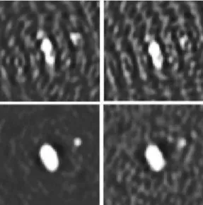
Figure 1. : Image reconstruction from simulated high-SNR data of an elliptical star with a companion which is approximately 3.4 magnitudes fainter than the primary. The upper images are re-constructed from simulated data using the beams from only 4 tele-scopes (i.e 6 instantaneous baselines), while the lower images are reconstructed from an array of 6 telescopes (i.e 15 instantaneous baselines). In each case an earth-rotation synthesis of 6 hours du-ration was simulated. The leftmost images are reconstructed from uncorrupted phase data, simulating data from a phase reference system, while the rightmost images are reconstructed from closure-phase data. All images have the same greyscale levels. It can be seen that the difference between images reconstructed from 4-telescope data and those reconstructed from 6-4-telescope data is far greater than the difference between images constructed from phase-referenced data and from closure phase data.
The imaging paradigm VSI is intended to be an imager with spectral resolution. The final astronomical product will therefore be an image at each spectral channel. VSI will be able to measure sufficient visibilities and phase information to permit model-independent image reconstruction. This puts a strong constraint on the number of (u, v) points for which one needs to obtain visibility, closure phase and differential-phase measurements. In particular increasing the number of telescopes has an immediate impact on the amount of phase information that can be retrieved through the use of closure phases quantities. The importance of retrieving phase information is considerable and three options arise: (i) using a second source as a phase reference; (ii) using the closure phase technique; (iii) in peculiar cases using spectral differential phases;
The closure-phase technique allows us to retrieve atmosphere-free phase information. In a standard interfer-ometer absolute phase information is lost due to multiple wave-front perturbations, (optomechanical instability, atmospheric piston). Using combination of at least three telescopes allows to extract the so-called closure-phases by summing up each baseline interferogram phases. This summation cancels out all the parasitic phase pertur-bation and produces the closure phase. Using an increasing number of telescopes allows to reduce the amount of phase information difference between phase and closure phases. Although extracting phase information from closure phase measurements is a tough work a considerable amount of research to find efficient algorithms has been carried (radio) and is still underway. We believe that the considerable relaxation of instrumental/operation constraints introduced by the use of closure phase quantities instead of phases is worth the already successful effort to find numerical ways to reduce the degeneracy when phases are extracted from closure phases.
Of course the possibility of accessing directly to phase measurements is very interesting and the phase-A study will include a detailed study of the impact of phase vs. closure phase measurements on the final image reconstruction capability. However we can anticipate that the gain in terms of image quality due to the use of phase instead of closure phase might not be as important as the gain due to the increase in the number of telescopes. See Fig. 1 and caption for an illustration. It should be remembered that imaging with the VLTI, which requires a good level of cophasing will have an important impact on VLTI operation.
Image complexity Image complexity depends directly on the ability to cover the (u,v) plane with a great number of independent visibility, phase/closure phases measurements.
Dynamic range The science case has determined that imaging with a dynamic range of 100 should allow to fulfill a significant fraction program. The conditions at which a dynamic range of 1000 can be reached should be studied.
Spectral coverage and dispersion requirement The science case study has defined operation at J, H and K bands with two to three spectral resolution spanning the [100,10000] domain as the minimum configuration. Some programs in the different legacy surveys may require R≈ 30000.
Limiting magnitude Currently the faintest objects contained in the science case have magnitudes of H, K ≈ 14.
Field of view The science case is mainly focused towards “compact” sources i.e sources that are not individ-ually resolved by the UTs at their diffraction limit. Currently most of the science programs require a field of view no bigger than 0.2”. During phase A the science group will have to define: (i) if the sources are indeed unresolved by individual apertures; (ii) the interest in increasing the field of VSI, so that it is able to map extended structures (in the sense of bigger than individual diffraction fields of view).
Time resolution VSI will be able to provide an image within one night. However the phase A science study should take into consideration the impossibility to move the telescope configuration during the night (especially with four telescopes) and should evaluate the impact on science of observing the same object with different configurations obtained at different epochs. Currently preliminary science cases have pointed out objects with intrinsic variability ranging from 1 hour to 1 month.
3.2. VSI external constraints
Atmospheric refraction and dispersion Since stellar light passes through a prism of atmosphere, the different wavelengths are refracted with different angles that depend upon zenithal angle. These refraction angles significantly vary from a spectral band to another, and even through a spectral band, as detailed and shown in the AMBER studies. So, the resulting image spots in the J and H bands are spectrally dispersed and thus appear elongated of an order of a few Airy disks. In the particular case of a single-mode instrument this leads to a coupling efficiency degradation at the extreme wavelengths of these bands. Another consequence lies in the fact that the angle between the beam direction provided by the adaptive optics device to the image sensor and the direction of the actual observing wavelength varies with time, inducing a variation of the coupling efficiency.
Atmospheric dispersion Since stellar light does not follow the same horizontal optical path in the air, an optical path difference (OPD) proportional to the interferometric baseline and to the projection of the zenithal angle on the meridian plane exists. As computed in the AMBER studies, this effect is rather negligible with the exception of long baselines and at low spectral resolution. In these cases, visibility loss can reach several percents but quickly decrease with spectral resolution. Moreover the corresponding bias can be well modeled.
Field of View Whatever the telescopes, the unvigneted field of view (FOV) at the instrument input has a diameter of 2”. The ESO facility PRIMA allows a dual-feed mode with two FOV of 2”, separated by an Airy disk at least and picked up anyway on the global Coud´e field of 2’.
Beam optical quality The typical tip-tilt error budget provides errors smaller than 21 mas rms on the sky with the UTs, and than 30 mas rms on the sky with the ATs, in the single feed mode. Based on the current experience with AMBER it seems reasonable to reassess the tip/tilt performances at VLTI in order to determine the need for an additional module integrated to VSI that would allow additional tip/tilt and/or higher order modes adjustment.
Optical path differences The VLTI has been designed to be intrinsically stable and, without fringe tracking, internal VLTI OPD fluctuations of 338 nm in K band are expected for an exposure time of 48 ms.
Polarization The VLTI has been designed to minimize the differential polarization effects thanks to symmetric optical trains. Nevertheless due to multiple reflections in each arm, various optical coatings, aging of these coatings, etc. residual polarization effects as partial polarization and phase shifts between the two perpendicular directions of linear polarization and/or between two different interferometric arms remain.
VLTI throughput The VLTI throughput with the UTs and the ATs equals from 20% up to 35% over the J, H and K bands, according to the wavelength and the optical configuration.
3.3. Functional analysis
We have carried out a sub-system breakdown in order to define for each of the instrument functions what were the studies that had to be addressed during the phase A study. At the current level of the study we have not merged any of the two different concepts (BOBCAT and VITRUV) but we can reasonably agree on the subsystem breakdown. As we will see in next section the preliminary conceptual designs arising from that are quite different and the phase A study will have to define the best concept. The VSI 14 subfunctions are made of:
1. atmospheric dispersion compensator; 2. spatial filtering;
3. wavefront correction; 4. fringe tracking; 5. optical path scanner; 6. beam injection; 7. beam combiner; 8. polarization control; 9. spectral dispersion; 10. detector; 11. data processing;
12. calibration and alignment tools;. 13. control module;
14. image reconstruction.
It should be stated that some of the previous subsystems might be irrelevant depending on the final beam combination concept adopted. Also the fringe tracking instrument should be seen as an instrument by itself.
4. CONCEPTUAL DESIGNS
This section presents the technical solutions selected for the sub-systems of VSI.
4.1. Integrated optics
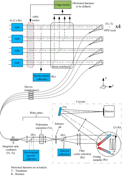
The combination proposed here is realized with Integrated Optics technology. This one is well suitable to the combination of four telescopes or more and the performances in terms of stability and efficiency have been demonstrated at several occasions on VLTI3, 4 and IOTA.5, 6Figure 2 describes a conceptual study of the science beam combiner derived from our system analysis. This last is composed of the following subsystems:
• Atmospheric dispersion compensator modules; • Alignment/calibration module;
• Beam switchyard/Fringe tracker; • Beam injection module;
• Spatial filtering;
• Beam combination module;
• Polarization control module; • Spectrograph;
• Spectral calibration module; • Detector;
• Control software;
The control Software and data reduction aspects are not represented in the figure but their functions are approached in the next sections. As it is proposed in the system analysis, the combination of 4 VLTI beams is our baseline while the combination of 6 or 8 beams is proposed as an additional option. We have considered IO technology as our solution to combine the 4 to 6/8 VLTI beams. This choice is based on LAOG experience on this type of combination which has been successfully exploited at VLTI (2-way beam) and IOTA (2,3-way beam combiners). The main advantages of this technology are:
Figure 2.Schematic view of the beam combiner concept
• possibility to integrate on single chip almost all combination schemes;
• it is easy to implement the modal filtering function associated to photometric calibration which has proved to be a key element in the improvement of the visibility accuracy;
• the very compact size of the combining chip allows a remarkable stability of phase properties and a small combining footprint;
• easy to install since only the alignment with the spectrograph has to be ensured;
Each beam combiner is made of an integrated optics chip connected to a fiber V-groove. At the present state of the study, the capability to use of only one chip to recombine both the J and H bands has not been demonstrated. Our baseline is consequently to ensure the combination of the 4 VLTI beams with three components, one component per spectral band. In the global study of the combiner, we foresee to study however the use only one IO component for both J and H bands.
Among all the beam combination concepts, our system study has pointed out that a four way pairwise ABCD beam combiner was the best compromise as far as signal to noise and biases are concerned. Our industrial partner LETI has designed such a combination concept.
Motorised functions are in brackets T − Translation R − Rotation Y X Z
Components may need tip/tilt adjustments. 6 x (Tz, Tx) Cryostat − Spectrograph ADC ADC ADC ADC ADC ADC Entrance slit
Fringe tracker Light dump
Beam switchyard OPD
Tracker
6 x (2 x Rz)
4 x (Tx, Tz)
Fiber injection Beam Combiner Slabs HR Detector Grating turntable (Ry) MR (Rz)
Filter (order selction)
Switchyard
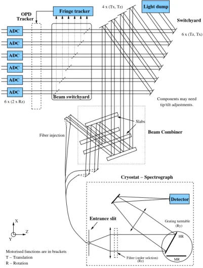
Figure 3.Schematic layout for the bulk-optics combiner. The layout for an instrument accepting 6 input beams is shown,
including a switchyard for selecting a subset of the beams to feed into a 4-way combiner.
4.2. Bulk optics
The bulk-optics (BO) option is an alternative to the integrated-optics (IO) science combiner which offers a number of potential advantages. Chief amongst these is the combination of high photon throughput (>96%) and high fringe contrast (>95%) which has been demonstrated in working prototypes.
The BO science combiner has the same basic functionality as the IO combiner. The main difference in implementation is the use of free-space optics rather than guided-wave optics for producing the interference patterns. A number of beam combination modes are possible within the BO concept, including image-plane and pupil-plane combination, as are a number of spatial filtering modes such as pinhole and fibre filtering. For simplicity we describe here mainly the baseline option, which uses pupil-plane beam combination and fibre spatial filtering.
A schematic diagram of the overall instrument is shown in Figure 3. Light entering the instrument is split using dichroics between the science beam combiner and the fringe tracker. The dichroics form part of a “beam switchyard” which feeds light into the main beam combiner. This is a 4-way pupil-plane design using beam splitters which produces 4 outputs, each being the superposition of all 4 input beams, i.e. interference patterns corresponding to all 6 possible baselines are present in each output. The fringes are “fluffed out” i.e. each output beam is either all light or all dark depending on the phases of the fringes. Path modulators serve to rapidly scan the phase of the input beams such that a temporally-modulated intensity is observed, with each of the 6 fringe patterns appearing at a separate frequency. The collimated outputs from the combiner are focused
onto single-mode fibres, serving to spatially filter the fringes and also to inject light into the input “slit” of a cooled spectrograph. The spectrograph illuminates a detector which is read out synchronously with the fringe modulation to produce a spectro-interferogram. This can be processed to yield fringe amplitude and phase information for all 6 baselines at a large number of wavelengths simultaneously.
This design is described further below in terms of a system analysis into a number of different functions:
• Atmospheric dispersion compensator modules; • Alignment/calibration module;
• Beam switchyard/Fringe tracker; • Science beam combiner;
• Fast path modulators • Beam injection module;
• Spatial filtering; • Spectrograph;
• Spectral calibration module; • Detector;
• Control software;
It can be seen that there is a large amount of commonality with the IO solution, so in many cases the reader will be referred to the IO sections for further detail (see section 4.1). The only module in the IO concept for which there is no equivalent in the BO concept is the polarisation control module: the BO solution requires no compensation for instrumental birefringence. The fast path modulators are present only in the BO concept as path modulation is done statically in the IO combiners.
The functionality of the beam switchyard is similar to that in the IO beam combiner, except where a 6-beam concept is implemented. With 6 input beams, the science beam combiner in the BO concept remains a 4-way design, but the switchyard serves to select subsets of the input beams to feed to the combiner. Interferometric data are accumulated with different subsets of input beams, with rapid (timescales of under a minute) switching between subsets. This allows sampling of all possible baselines and closure phases in a short period. As a result, the switchyard needs to be designed for rapid reconfiguration.
The optical arrangement which allows all 4 input beams to be superimposed using beam splitters is shown in the box labelled “beam combiner” in Figure 3. The design uses custom-designed coatings at low angles of incidence for high efficiency and low polarisation sensitivity, and components are connected using contacted-optics technology to achieve exceptional path length and alignment stability. The wide-band nature of the coatings means that only one combiner is needed to cover the J, H and K bands. The design is based on a working prototype in Cambridge which has demonstrated the required high throughput and stability. The work in the phase-A study would mainly involve looking at scaling issues for the larger VLTI beams.
The optical path difference between beams is modulated at rates of several hundred Hertz using mirrors mounted on piezoelectric actuators. Laboratory tests have shown that the scanning of these mirrors can achieve the required accuracy and repeatability by appropriately controlling the harmonics of the drive waveform. Studies thus far have used feedback from direct measurements of the resulting modulation using a metrology laser, but injecting laser metrology to all the modulators could be problematic within the space envelope. Alternative options for performing the calibration of the drive waveform include use of capacitive or strain-gauge sensors.
The injection of light into fibres in the BO design occurs after beam combination, so the phase and birefrin-gence properties of the fibres are of little concern. If suitable fibres (e.g. chalcogenide photonic crystal fibres) can be procured, then only a single set of fibres may be needed to cover all wavebands. The beam injection technology described for the IO combiner would be appropriate for application in the BO concept.
The detector and spectrograph layout and requirements in the BO concept are similar to that for the IO concept. One difference is that the BO spectrograph has fewer outputs which are read out more often than the IO spectrograph, but the overall pixel rate is similar.
4.3. Fringe tracker
A fringe tracker performs a similar role within an interferometer as an adaptive optics (AO) system performs within a single telescope. It measures wavefront errors due to the atmosphere and instrument (in the case of a fringe tracker, these OPD errors are the differences between telescopes of the amplitudes of their respective
Zernike “piston” modes) and corrects these errors in real time. Like an AO system, a fringe tracker requires a bright reference object to sense the wavefront errors, and also like an AO system there are strong fundamental limits to how faint this reference object is allowed to be before the fringe tracker fails to operate. If the fringe tracker does not work, little or no science can be done, and so the range of science targets accessible to the instrument is typically most strongly limited by the performance of the fringe tracker, especially its magnitude limit. Because of this intimate relationship between fringe tracker performance and the science performance of the system as a whole, VSI will incorporate its own fringe tracking subsystem. The combined system of fringe tracker and science beam combiner will be optimised as a whole to meet the science requirements.
In order to fulfill the science goals of high-throughput acquisition of data, high-SNR high-spectral-resolution imaging, and imaging of complex faint objects, the fringe tracker will operate in a minimum of three distinct modes defined as follows:
Fringe acquisition This is a mode in which a finite region of OPD space is scanned in order to find the fringe coherence envelope in the presence of atmospheric and instrumental delay uncertainties. This mode will typically use either a continuous or stepped scan of the delay lines together with a group-delay algorithm to efficiently detect the presence of fringes over a region of delay space set by the coherence length of a single spectral channel.
Hardware phase tracking This is a mode in which the delay errors are actively compensated at high speed so that the level of stability of the science combiner fringes is sufficient to allow on-chip integration of the fringe signal over periods of many atmospheric coherence times. Typically hardware phase tracking requires a high SNR fringe phase measurement to be made in a short integration time to allow the high-precision (typically of order λ/20) correction required. This means that a bright (mH < 10) reference object is required, but providing such a reference is available, then the long coherent integration times afforded on the science combiner allow high-spectral-resolution measurements to be made relatively rapidly.
Hardware coherencing This is a mode in which the delay errors are compensated in real time but at a lower speed, with sufficient precision to ensure that the loss in fringe contrast due to temporal coherence effects is small over incoherent integration periods of many minutes. Using group-delay tracking methods on spectrally-dispersed fringes,7 the fringes can be tracked using reference stars at least 2.5 magnitudes fainter than are usable with phase-tracking methods.8 In addition, in the presence of short-term Strehl “dropouts” and phase branch point effects due to imperfect AO correction, group delay methods are considerably more robust. Thus the hardware coherencing mode will be most beneficial for science on faint targets and/or in moderate to poor seeing. In this mode, the science combiner will need to be read out at rates comparable to the atmospheric coherence time, rather than the longer integration times afforded by the phase-tracking mode.
A conceptual layout for the fringe tracker is shown in Fig. 4. The subcomponents of the fringe tracker which are described have been separated into:
• Dichroics
• Beam switchyard;
• Fringe-tracking beam combiner; • Fast path modulators
• Low-resolution spectrograph and detector; • Control system;
• OPD corrector;
A complete optical and mechanical design of the fringe-tracking combiner optics is needed to ensure that the combiner can be fitted within the space envelope at the VLTI.
A key parameter of the science case for the instrument as a whole will be the list of which potential science targets can be observed in a high-spectral-resolution phase-tracking mode and which can be observed in a faint-object coherencing mode. Detailed calculations of the magnitude limits for both these modes will feed into the determination of these potential target lists.
Figure 4. Conceptual layout of the fringe tracker optics
The maximum coherent integration time, and hence SNR, for the science combiner when the fringe combiner is in phase-tracking mode will be strongly limited by drifts in the relative OPD as measured by the fringe tracker and as seen by the science beam combiner. Various methods of “tying together” the beam combiners using either mechanical means or laser metrology will be evaluated to determine the practical limits to achieving long coherent integrations and the most cost-effective means for achieving these.
The real-time component of the fringe tracker derives adjustments to the OPD from the pixel data stream arriving from the detectors. In both the coherencing or phase-tracking modes the fringe amplitude and phase are derived for each of the 5 spectral sub-bands at rates of up to several hundred Hz. Typically 4 fringe samples need to be taken synchronously with the OPD modulation in order to derive the fringe parameters, so that 20 pixels in total need to be processed per coherent integration per baseline being tracked. For 5 baselines being tracked at a sample rate of 500Hz, the data rate is 50ksamples/sec. This is not a demanding computational task, and so specialised computing hardware (e.g. DSP arrays) is not necessary — it should be possible to perform all the real-time computation on a single Pentium-class processor running a hard real-time operating system.
The fringe-tracking computer filters the derived OPD errors and sends the appropriate signals to a two-stage OPD correction system consisting of a mirror mounted on a fast piezo-electric stage connected which takes out rapid pathlength fluctuations, and, error signals sent to the delay line signals to correct long-term large-amplitude OPD errors.
5. CONCLUSION
VSI is proposed as second generation VLTI instrument providing the ESO community with the capability of performing image synthesis at milli-arcsecond angular resolution. VSI provides the VLTI with an instrument capable of combining 4 telescopes in a baseline version and optionally up to 6 telescopes in the near-infrared spectral domain with moderate to high spectral resolution. The instrument contains its own fringe tracker in order to relax the constraints onto the VLTI infrastructure. Two solutions for the science beam combiner were identified one based on integrated optics and another on bulk optics:
• The integrated optics science beam combiner solution has been validated with astrophysical results at high performance on IOTA and VLTI. It emphasizes the maintainability of the instrument (apart from the injection devices, there are no degrees of freedom left for the beam combination); it is well suited to feed a conventional infrared spectrograph; enhancing the number of telescopes from 4 to 6 just requires a different IO device which can be fed by different fibers and the duplication of 2 more injection modules.
• The bulk optics science beam combiner solution has an emphasis on the commonality with the integrated optics solution. It is based on a 4-way working prototype in Cambridge. Although having a larger number of degrees of freedom, it has high optical throughput and interferometric contrast. To work with 6 telescopes, the beam combiner requires fast switching optics in order to select subsets of the input beams to feed the 4-way beam combiner. The 4 outputs of the beam combiner are injected in fibers to feed a similar spectrograph as the one designed for the IO solution.
These two solutions are inherited from the two concepts merged. One of the goals of the Phase A study is to define which of them will be used by VSI. The phase A starts in June 2006 and will last one year until the study will be reviewed by ESO who will take a final decision.
REFERENCES
1. F. Malbet, J.-P. Berger, P. Garcia, P. Kern, K. Perraut, M. Benisty, L. Jocou, E. Herwats, J.-B. Lebouquin, P. Labeye, E. Le Coarer, O. Preis, E. Tatulli, and E. Thi´ebaut, “VITRUV - Imaging close environments of stars and galaxies with the VLTI at milli-arcsec resolution,” in ”The Power of Optical/IR Interferometry: Recent Scientific Results and 2nd Generation VLTI Instrumentation”, ESO conference, Garching, Germany, in press, pp. (astro–ph/0507233), 2005.
2. D. Buscher, F. Baron, J. Coyne, C. Haniff, and J. Young, “BOBCAT - a photon-efficient multi-way combiner for the VLTI,” in ”The Power of Optical/IR Interferometry: Recent Scientific Results and 2nd Generation VLTI Instrumentation”, ESO conference, Garching, Germany, in press, 2005.
3. J. B. LeBouquin, K. Rousselet-Perraut, P. Kern, F. Malbet, P. Haguenauer, P. Kervella, I. Schanen, J. P. Berger, A. Delboulb´e, B. Arezki, and M. Sch¨oller, “First observations with an H-band integrated optics beam combiner at the VLTI,” A&A 424, pp. 719–726, Sept. 2004.
4. J.-B. Le Bouquin, P. Labeye, F. Malbet, L. Jocou, F. Zabihian, K. Rousselet-Perraut, J.-P. Berger, A. Del-boulbe, P. Kern, A. Glindemann, and M. Schoeller, “Integrated optics for astronomical interferometry - VI. Coupling the light of the VLTI in K band,” A&A in press, pp. (astro–ph/0512544), Dec. 2005.
5. J. D. Monnier, W. A. Traub, F. P. Schloerb, R. Millan-Gabet, J.-P. Berger, E. Pedretti, N. P. Carleton, S. Kraus, M. G. Lacasse, M. Brewer, S. Ragland, A. Ahearn, C. Coldwell, P. Haguenauer, P. Kern, P. Lab-eye, L. Lagny, F. Malbet, D. Malin, P. Maymounkov, S. Morel, C. Papaliolios, K. Perraut, M. Pearlman, I. L. Porro, I. Schanen, K. Souccar, G. Torres, and G. Wallace, “First Results with the IOTA3 Imaging Interferometer: The Spectroscopic Binaries λ Virginis and WR 140,” ApJL 602, pp. L57–L60, Feb. 2004. 6. S. Kraus, F. P. Schloerb, W. A. Traub, N. P. Carleton, M. Lacasse, M. Pearlman, J. D. Monnier, R.
Millan-Gabet, J.-P. Berger, P. Haguenauer, K. Perraut, P. Kern, F. Malbet, and P. Labeye, “Infrared Imaging of Capella with the IOTA Closure Phase Interferometer,” AJ 130, pp. 246–255, July 2005.
7. A. G. Basden and D. F. Buscher, “Improvements for group delay fringe tracking,” MNRAS 357, pp. 656–668, Feb. 2005.
8. D. Buscher, “Low light level limits to tracking atmospheric fringe wander,” in Quantum Limited Imaging and Information Processing”, 1989 Technical Digest Series (OSA), in press, pp. (astro–ph/0507233), 2005.