1
Submitted Manuscript
Oxidation/corrosion of BN and B(Al)N coatings, as future BN-based
interphases in SiC/SiC composites: relationship with the degree of
crystallization, the orientation of crystallographic structure and effect of
aluminium addition
Paul CARMINATI, Sylvain JACQUES*, Francis REBILLAT
LCTS UMR 5801, CNRS - University of Bordeaux, 3 allée de la Boétie, 33600 Pessac, FRANCE *corresponding author
Abstract
The ceramic matrix composites envisaged as structural parts in the hot section of aircraft engines consist of SiC-based fibres and matrices with a BN interphase coating between them. To control their service life, the oxidation/corrosion behaviour of these materials must be determined. For this purpose, samples of different geometries were prepared by chemical vapour deposition and thermally subjected to wet air. The behaviour of BN alone depends on its crystallization degree, structural homogeneity and the considered direction in the coating. In the case of a thin layer of pure BN of interphase type, recession is significantly reduced at 800°C by the formation of a sealing borosilicate phase in the confined space surrounded by SiC. At 1000°C, the protection is no longer sufficient and a steady recession remains. The presence of aluminium added to BN improves protection at 1000°C due to the formation of alumina combined with borosilicate.
Keywords
boron nitride; aluminium; corrosion; interphase; thermogravimetric analysis
1. Introduction
Ceramic matrix composites (CMCs) are intended to be used as structural parts in the hot section of aircraft engines such as turbine rings and blades [1]. The desired service life for such parts is more than 50,000 hours of use. Thus, the oxidation/corrosion resistance of the materials at high temperatures must be taken into account, and even becomes a key property of the composites under consideration. The proposed CMCs are of the SiC/SiC-type, i.e. made up of silicon carbide-based long fibres and matrix with the addition of a turbostratic boron nitride (t-BN) interphase [2] [3]. The latter constituent is a sub-micrometric thin coating deposited by a method derived from chemical vapour deposition (CVD) on the fibres before the matrix. The t-BN deposited by CVD and used as an interphase can have different microstructures and degrees of crystallization depending on the processing conditions [4] [5] [6] [7] [8]. The role of the interphase is essential to the proper functioning of the CMC [9], it must be preserved during the use of the CMC in the oxidizing and corrosive environments of the aircraft engine [10].
2
BN oxidises passively: it leads to the formation of liquid B2O3, which remains in a condensed form up to about 1000 °C in dry air due to its low saturating vapour pressure [11]. The formed oxide scale can therefore act as a diffusion barrier against the oxidizing species on the boron nitride surface. However, in the presence of water vapour, B2O3 volatilises as boron hydroxides HxByOz (x, y and z depending on temperature) [12] [13]. Inside composite, the presence of B2O3 can contribute to accelerate the oxidation of the silicon carbide constituting the fibres and matrix by dissolving the passivating silica scale formed by oxidation of SiC [14] [15] [16] [17] [18]. Thus, under wet air at high temperature, two cases are possible: (i) the oxidation of SiC is not fast enough to allow the formation of a borosilicate glass and the interphase is replaced by a gap: the mechanical load transfer between fibres and matrix is no longer ensured and the fibres can be surface degraded or (ii) a borosilicate glass rich in silica is formed in place of the interphase part consumed by oxidation: the silica, which is more viscous than B2O3, then allows getting a less reactive glassy phase against moisture and an effective healing of the cracks at high temperature. In an air environment, the BN recession with gap formation or the protection of the interphase depends on the oxidation temperature as shown in SiC/SiC minicomposites by Morscher et al. [19] [20] and Yang et al. [21]. However, the presence of a glassy mixture can also lead to bridging between the fibres and the matrix, resulting in potential embrittlement of the composite when cold. To keep the integrity of the composite, its formation must therefore remain localised. In addition, a very high moisture content as found in aircraft engines can, by corrosion, reduce the protective effect of the formed oxide and lead to the attack of the fibrous reinforcement [22] [23]. An improvement in the resistance to oxidation and hydrolysis of BN interphases can be achieved by Si-doping [20] [24]. Adding aluminium to the BN interphase can be another interesting way to improve its oxidation/corrosion behaviour. It has indeed been shown that the use of an AlN-BN multilayered system consisting of alternating thin sub-layers of different nitrides can reduce B2O3 volatilization through the formation of aluminium borates [25].
The aims of this work were to establish the relationships between the oxidation/corrosion behaviour of BN interphases at 800-1000 °C in wet air, the degree of crystallization and the orientation of the crystallographic structure of BN. Finally, the effect of aluminium addition on the oxidation behaviour of the interphase was evaluated. For this end, aluminium was incorporated directly by CVD into the boron nitride as a co-deposition rather than in the form of alternating sub-layers of different natures, to ensure the most intimate contact possible between Al and B.
2. Experimental procedure
2.1 Samples and coatings
The apparatus used in this study to deposit the different coatings was the same as that used in the previous study by Carminati et al. on CVD of BN [7]. It was a hot-wall CVD reactor working at low pressure. Pure t-BN coatings were deposited from NH3 and BCl3. A gaseous precursor of aluminium was also added to the precursors of BN to deposit aluminium-containing boron nitride coatings, denoted B(Al)N. Two types of substrates with different geometries were used to be able to establish relationships between the oxidation/corrosion behaviour of BN interphases and the orientation of the crystallographic structure of BN; thus, the oxidation of BN coating could either propagate parallel or perpendicular to the basal planes of sp2-hybridized BN. In all cases, the basal planes of sp2-BN were predominantly parallel to the CVD growing surface.
The first type of substrate was used to obtain flat samples. These were 5 mm × 5 mm silicon wafers. BN or B(Al)N coatings were deposited on the rough side of the wafers to promote better adhesion. However, the variation in surface height due to roughness remained less than 1 µm on the wafers. These flat substrates were degreased with acetone in an ultrasonic bath and treated with hydrofluoric acid to remove any native oxide layer (SiO2) present on their surface before being used in CVD. The thicknesses of the deposited coatings ranged from 5 and 10 µm for pure BN and from 10 and 15 µm for B(Al)N.
3
These "thick" coatings were characterized by X-ray diffraction (XRD) (θ/θ diffractometer Brucker D8 Advance λCuKα1 = 0.15419 nm). XRD patterns were acquired on a 2θ range of 20-30° in order to focus analysis on the peak related to the diffraction from adjacent basal planes of sp2-BN. The degree of crystallization of the coatings was estimated from Lc (coherence length) and d (interreticular distance between the sp2-BN basal planes). The structural homogeneity of the coatings was estimated from the η factor calculated from the shape asymmetry of the XRD peaks. This asymmetry was attributed to the coexistence of poorly and highly organized domains in the coatings. When the coating of BN is homogeneous η is 1, and the more heterogeneous the coating is, the lower the value of η [7].
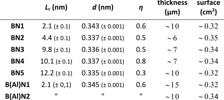
Five different types of BN with different degrees of crystallization were deposited using a combination of temperature, initial gas phase composition, residence time in the CVD reactor and carrier gas nature [7]. The characteristics of these deposits denoted as BN1 to BN5 are gathered in Tab. 1. Concerning more specifically the deposition temperatures, BN1 was deposited at 900 °C and was heat treated at 1400 °C for 2 hours. BN2, BN3 and BN4 were deposited at 1200 °C while BN5 was deposited at 1400 °C. In the latter case, due to the deposition temperature close to the melting point of Si, a flat sintered SiC substrate was used. Two B(Al)N coatings, denoted as B(Al)N1 and B(Al)N2, were deposited under the same CVD conditions as BN4, in particular with the same deposition temperature of 1200 °C, and with the aluminium precursor added in the gas phase. Only the deposition time was changed between B(Al)N1 and B(Al)N2 and therefore only their thicknesses, 15 µm and 10 µm respectively, are different (Tab. 1). Lc (nm) d (nm) η thickness (µm) surface (cm2) BN1 2.1 (± 0.1) 0.343 (± 0.001) 0.6 . BN2 4.4 (± 0.1) 0.337 (± 0.001) 0.5 . BN3 9.8 (± 0.1) 0.336 (± 0.001) 0.5 . BN4 10.1 (± 0.1) 0.337 (± 0.001) 0.8 . BN5 12.2 (± 0.1) 0.335 (± 0.001) 0.3 . B(Al)N1 2.1 (± 0,1) 0.345 (± 0.001) 0.6 . B(Al)N2 " " " .4
Tab. 1 XRD structural parameters, thicknesses and surfaces of BN and B(Al)N flat coatings
The different samples were observed before and after oxidation/corrosion tests by Scanning Electron Microscopy (SEM, QUANTA 400 FEG) with an accelerating voltage of 5 kV. Chemical analyses were also performed in the microscope by Energy Dispersive X-ray Spectroscopy (EDS) with an accelerating voltage of 10 kV.
According to the EDS analyses, B(Al)N coatings contain about 9 at% aluminium (Tab. 2). The degree of crystallization of residual BN in these coatings is very similar to that of the previous least crystallized aluminium-free coating, i.e. BN1 (Tab. 1). The composition of BN1 is given for comparison in Tab. 2.
B C N O Al
BN1 46 4 46 4 0
B(Al)N 39 3 47 2 9
4
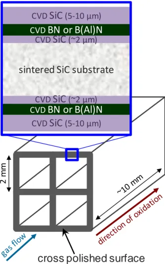
The second type of substrate differs by its geometry. These were sintered SiC cellular substrates on which multilayer SiC/BN/SiC or SiC/B(Al)N/SiC coatings were deposited by CVD. The coatings consisted of a first SiC layer ~2 µm thick, then a BN or B(Al)N layer and finally a final SiC layer 5-10 µm thick. The SiC layers were deposited by CVD from a mixture of hydrogen and methyltrichlorosilane at a temperature of about 1000 °C. The pure BN layers sandwiched between the SiC layers were either "thick" (4 µm) or "thin" (0.5 µm). In the case of B(Al)N, only thin layers were deposited.
Once the different layers were successively deposited on these substrates, their section was polished to expose the coating on only one section perpendicular to the cell axis (Fig. 1). The samples were then oxidized/corroded at high temperature by applying a flow of wet air to the cross polished surface.
Fig. 1 Schematic representation with enlarged view of the cross polished section (= cutting edge surface) of a
multilayer model material SiC/BN/SiC (BN thickness = 4 µm or 0.5 µm) or SiC/B(Al)N/SiC (B(Al)N thickness = 0.5 µm) before oxidation/corrosion test.
The oxidised/corroded material was then embedded in epoxy resin, cut and polished perpendicular to the side exposed to the oxidising flux (i.e. in the direction of oxidation/corrosion), so as to measure, from SEM observations, the length of recession of the BN or B(Al)N layer caused by oxidation/corrosion through the sample.
2
m
m
sintered SiC substrate
CVD
SiC
(~2 µm)
CVD
SiC
(5-10 µm)
CVD
BN or B(Al)N
CVD
SiC
(~2 µm)
CVD
SiC
(5-10 µm)
CVD
BN or B(Al)N
5
2.2 Oxidation/corrosion tests
In order to establish the oxidation kinetic laws of these materials, the oxidation tests were performed by heating the sample, in a thermogravimetric analysis (TGA) apparatus or in a tubular furnace, under controlled gaseous environment. TGA were performed using Setsys 1600 from Setaram. The specimens were placed in wet air (10 kPa H2O, 70 kPa N2, 20 kPa O2), at 800 °C with a gas velocity of ~0.7 cm/s and at 1000 C with a gas velocity of ~0.8 cm/s. To obtain wet conditions, a dry gas mixture was saturated with water vapour by bubbling through a wash bottle, maintained in a thermally controlled bath. The temperature of the bath was fixed to a value corresponding to the required PH2O(g). To perform the tests, the samples were placed in an alumina crucible in a furnace with a pre-aged alumina tube to minimize catalysis of oxidation reactions by the presence of sodium-based impurities [26]. The samples were heated and then cooled down at 10 °C/min and 20 °C/min respectively under a neutral atmosphere (argon) to avoid any oxidation during these steps. The mass measurements were performed during a temperature plateau as soon as the moist oxidizing gaseous mixture was introduced into the analysis chamber. The mass variation was measured with time and expressed per unit of reactive BN surface area. The test duration depended on the temperature, but it did not exceed 60 hours at low temperature or on cellular substrates and 5 hours at higher temperature or on flat substrates.
For flat samples, the mass variation of a similar empty crucible was subtracted to the raw mass measurements for each tested condition. The thick coatings on flat substrates were tested in oxidation/corrosion at 800 °C except B(Al)N2 tested at 1000 °C. The flat samples were used to evaluate the intrinsic oxidation/corrosion of BN perpendicular to the direction of the BN basal planes. It is worth noting that the absorption of hydrated species has been evidenced: the inverse phenomenon of desorption occurs if an extra stage under argon is added at working temperature [27]. The phenomenon is again reversible when the wet oxidizing gas mixture is reintroduced.
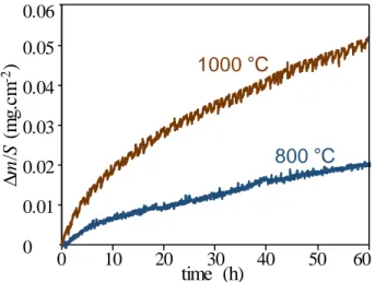
For the multilayer SiC/BN/SiC and SiC/B(Al)N/Si coatings, to obtain only the mass variations due to oxidation in the section of the BN-based coating, the contribution of the SiC surface oxidation must be subtracted from the overall mass variation recorded. For this purpose, substrates coated only with SiC CVD were first tested. As expected, the oxidation of SiC gives rise to a slight mass gain (Fig. 2), which follows a parabolic law due to the role of diffusion barrier of the silica scale formed on the surface of SiC [12], from the first moments of the oxidation test. Up to 1000 °C, the volatilization of silica is negligible. The thicknesses of silica formed after 60 hours were respectively about 30 to 40 nm for the test carried out at 800 °C and about 60 nm when the oxidation temperature was raised to 1000 °C.
Fig. 2 Specific mass variation of SiC coatings on cellular substrates in wet air (10 kPa H2O, 70 kPa N2, 20 kPa O2) at 800 °C (surface = 2.64 cm2) and 1000 °C (surface = 3.46 cm2)
20
800 C
1000 C
0 10 30 40 50 60time (h)
0 0.01 0.02 0.03 0.04 0.05 0.06∆
m
/S
(m
g.c
m
-2)
6
Still for the multilayer coatings, the 4 µm thickness of the sandwiched layer allowed the evaluation of intrinsic oxidation/corrosion resistance of BN in a direction parallel to basal planes. The progression of the oxidation front was indeed parallel to this direction. When the boron nitride layer was thin (0.5 µm), it became confined between the two SiC layers. The silica formed by the oxidation of SiC could contribute to sealing and its growth rate was increased in the presence of boron oxide (B2O3). Furthermore, the formation of a glassy borosilicate phase could reduce the volatilization of B2O3. A BN thickness of 0.5 µm is typical of that of an interphase in SiC/SiC CMCs, so that this geometry allowed the simulation of the oxidation behaviour of an interphase at a matrix crack or at a cutting edge surface in a composite. Mass variations due solely to the oxidation/corrosion of BN could be very small compared to those due to the oxidation/corrosion of SiC and could represent only a small proportion of the overall mass variation. In addition, the latter being expressed per unit area of reactive BN, the background of the TGA curve was exacerbated. Indeed, as the thickness of the BN was reduced (from 4 to 0.5 µm), this surface area was reduced by an order of magnitude (from ~1.10-3 cm2 to ~1.10-4 cm2).
3. Results and discussion
3.1 Thick coatings on flat substrates (oxidation/corrosion perpendicular to the BN basal planes)
3.1.1 Pure BN oxidation/corrosion at 800 °C
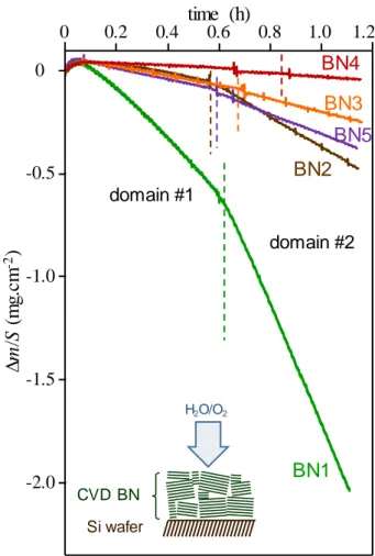
The specific mass variation plots recorded as a function of time at 800 °C for thick coatings on flat substrates show similar characteristics with two domains (Fig. 3). After a maximum reached after about a 3-minute test period, a first domain (#1) of seemingly linear mass loss appears. A change in slope is observed between the first and second domain at time tsat. In the second domain (#2) the mass loss is more pronounced. There is no B2O3 visible by SEM observation on the surfaces.
According to the model proposed by Willemin et al., following the short initial period of mass gain due to the absorption of oxidation/corrosion species, domain #1 corresponds to a paralinear behaviour where partial hydration of boron nitride and surface volatilization of the formed oxide as boron hydroxides occur simultaneously [27]. At the end of domain #1 at time tsat, the residual coating is saturated with hydrated species in its full thickness. There is no more absorption and therefore no more contribution to mass gain; the overall weight loss becomes faster. Linear domain #2 corresponds to the active oxidation of BN fully saturated with hydrated species, i.e. where the formed B2O3 is fully volatilized. The saturation time tsat defines the boundary between the two oxidation domains. For BN coatings of the same nature, tsat should be higher the thicker the coating. Conversely, for a given thickness, it should be lower when the coating is more sensitive to moisture diffusion/adsorption.
7
Fig. 3 Specific mass variation of thick BN coatings on flat substrates in wet air (10 kPa H2O, 70 kPa N2, 20 kPa O2) at 800 °C (oxidation/corrosion perpendicular to the BN basal planes)
The two linear domains exhibit different mass loss rates, noted respectively k1 and k2, with k2 > k1, the difference being more pronounced for the less organized boron nitride (BN1) (Tab. 3). According to Willemin et al., the slope of the TGA curves in domain #1 corresponds to the consumption of BN before saturation in hydrated species. The thickness of BN consumed per unit time kBN cons (in µm.h-1) can therefore be deduced from the mass loss rate obtained from the first linear domain by using Eq. (1), where k1 is in mg.cm-2.h-1 and ρBN is the density of BN. The value of ρBN used for the computations is 2.2 g.cm-3.
𝑘BN cons = (
|𝑘1| × 10−3
𝜌BN ) × 10
4 (1)
Similarly, the consumed BN quantity rate nBN (in mol.cm-2.h-1) can be calculated from Eq. (2), where MBN is the molecular mass of BN.
nBN = |𝑘1| × 10−3
𝑀BN (2)
Still according to Willemin et al., the ratio in slopes between the two linear regimes is due to the variation in mass balance between the two global reactions involved in hydration and volatilization [27]. However, the molar consumption rate of BN is expected to remain the same in both oxidation domains. Thus, this ratio can be directly related to the average molecular weight of the adsorbed species per mole of BN. With the reasonable assumption that the reactive surface area has not changed, the molecular mass of hydrated species MBNx.(OH)y
can be calculated using Eq. (3).
MBNx.(OH)y = |𝑘2| × 10−3
𝑛BN =
|𝑘2|
|𝑘1|𝑀BN (3)
MBNx.(OH)y - MBN
then represents the increase in mass per mole of BN due to absorption by hydration.
These different values derived from the TGA curves and calculated are shown in Tab. 3.time (h)
-2.0 -1.5 -1.0 0 0.2 0.4 0.6 0.8 1.0 1.2∆
m
/S
(m
g.c
m
-2)
Si wafer CVD BN H2O/O2BN1
BN4
BN2
BN5
0 -0.5 domain #1 domain #2BN3
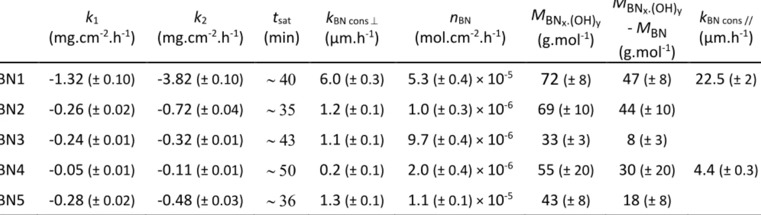
8 k1 (mg.cm-2.h-1) k2 (mg.cm-2.h-1) tsat (min) kBN cons (µm.h-1) nBN (mol.cm-2.h-1) MBNx.(OH)y (g.mol-1) MBNx.(OH)y - MBN (g.mol-1) kBN cons // (µm.h-1) BN1 -1.32 (± 0.10) -3.82 (± 0.10) 6.0 (± 0.3) 5.3 (± 0.4) × 10-5
72 (± 8)
47 (± 8) 22.5 (± 2) BN2 -0.26 (± 0.02) -0.72 (± 0.04) 1.2 (± 0.1) 1.0 (± 0.3) × 10-6 69 (± 10) 44 (± 10) BN3 -0.24 (± 0.01) -0.32 (± 0.01) 1.1 (± 0.1) 9.7 (± 0.4) × 10-6 33 (± 3) 8 (± 3) BN4 -0.05 (± 0.01) -0.11 (± 0.01) 0.2 (± 0.1) 2.0 (± 0.4) × 10-6 55 (± 20) 30 (± 20) 4.4 (± 0.3) BN5 -0.28 (± 0.02) -0.48 (± 0.03) 1.3 (± 0.1) 1.1 (± 0.1) × 10-5 43 (± 8) 18 (± 8)Tab. 3 Specific mass variation rates k1 and k2, saturation times in hydrated species tsat, consumption rates
kBN cons , consumed BN quantity rates nBN, molecular masses of hydrated species MBNx.(OH)y and masses
absorbed by hydration per mole of BN MBNx.(OH)y - MBN for thick BN coatings on flat substrates (oxidation/corrosion perpendicular to the BN basal planes) and consumption rates of 4 µm thick BN coatings on cellular substrates kBN cons // (oxidation/corrosion parallel to the BN basal planes) in wet air (10 kPa H2O, 70 kPa N2, 20 kPa O2) at 800 °C
The influence of the overall degree of crystallization can be assessed by first looking at the effect of the interreticular distance d. The samples BN2 to BN5 form a group of rather well crystallised coatings with d ≈ 0.336 nm close to the theoretical value for hexagonal BN (h-BN) [28]. They have all been deposited at a temperature of 1200 °C or higher and exhibit significantly lower mass losses and consumption rates than the BN1 coating. The latter having been deposited at 900 °C is rather poorly crystallized with d > 0.34 nm (Tab. 1). Thus, BN1 lost ~2 mg.cm-2 during this 1-hour test versus less than 0.5 mg.cm-2 for the others. Under these conditions, the consumption rate perpendicular to the basal planes of BN1 (kBN cons (BN1) = 6.0 µm.h-1) is about 30 times higher than that of BN4 (kBN cons (BN4) = 0.2 µm.h-1). This is the largest difference measured between the different samples. The oxidation resistance of boron nitride under wet air therefore depends on its degree of crystallization. This result is in agreement with the literature. According to Jacobson et al., a highly crystalline BN material oxidizes much more slowly in O2 with 20 ppm H2O than a less crystalline one [29]. According to Cofer and Economy, BN sensitivity to moisture with or without O2 decreases as d approaches the theoretical value for h-BN. d is a major parameter for the oxidation/corrosion resistance of boron nitride [30]. In the following part of this section, a more detailed analysis is given to the group of the best organized coatings (BN2 to BN5) with d ≈ 0.336 nm.
The influence of the coherence length can be assessed by comparing BN2 and BN3 which have the same structural homogeneity η. For these two coatings, the values of k1 and therefore of kBN cons are close (Tab. 3). However, the mass loss rate for the second linear domain (#2) of the plots is significantly higher in the case of BN2. Once BN is saturated with hydrated species, its active oxidation is faster (with k2(BN2) ≈ 2.25 x k2(BN3)) when Lc is low (with Lc(BN3) ≈ 2.2 x Lc(BN2)). A correlation seems to exist between the average crystallite size in the coatings and the amount of absorbed OH type species. This is moreover corroborated by the mass absorbed by hydration (MBNx.(OH)y - MBN) which, for a same η, is globally higher the smaller Lc is. Thus, the edges of coherent BN domains could be preferential places for diffusion/absorption of OH type species within the coatings. The saturation times per thickness, similar for both deposits, do not appear to be directly related to the amount of absorbed OH type species.
9
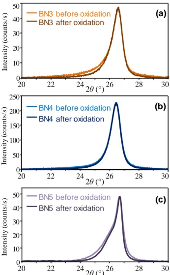
The comparison of the best crystallized coatings characterized by the largest Lc (~10 - 12 nm), BN3, BN4 and BN5, allows the determination of the influence of η. BN4, which has the highest structural homogeneity (Tab. 1), is the most resistant to oxidation/corrosion (Fig. 3 and Tab. 3). BN5, which is the least homogeneous, is the most sensitive to oxidation/corrosion, although this coating is slightly more crystallised than the others (largest Lc and smallest d due to the highest deposition temperature of 1400 °C). These results show that the structural homogeneity, which is not usually considered, is, after Lc, a parameter with a high impact on the oxidation/corrosion resistance of BN at high temperature. After the oxidation/corrosion tests at high temperature, BN3, BN4 and BN5 had a sufficient residual thickness to be characterized by XRD (Fig. 4). The cooling at the end of the test being under Ar, the residual BN coatings are dried. The asymmetry of the XRD peak of BN3 and BN5 is slightly reduced after the test. The values of Lc and d of BN3 are unchanged, while the average value of Lc of BN5 has increased slightly to 13.3 (± 0.1) nm instead of 12.2 (± 0.1) nm before oxidation. These changes result from a preferential consumption of the poorly organized areas in BN3 and BN5. Conversely, when the microstructure was initially already homogeneous, as for BN4, it does not change; the values of all parameters, Lc, d and η are identical before and after oxidation/corrosion. A coating of homogeneous structure oxidizes logically homogeneously along a neat front, while coatings of low homogeneity oxidize heterogeneously, with a preferential consumption in poorly organized areas.
Fig. 4 XRD peak related to the diffraction from adjacent basal planes for (a) BN3, (b) BN4 and (c) BN5 before and
after 1h15 of oxidation/corrosion in wet air (10 kPa H2O, 70 kPa N2, 20 kPa O2) at 800 °C. BN3 before oxidation BN3 after oxidation In te n s it y ( c o u n ts /s ) 10 0 20 30 40 50 20 22 24 26 28 30 2θ (°) (a) In te n s it y ( c o u n ts /s ) 50 0 100 150 200 250 20 22 24 26 28 30 2θ (°) BN4 before oxidation BN4 after oxidation (b) In te n s it y ( c o u n ts /s ) 10 0 20 30 40 50 20 22 24 26 28 30 2θ (°) BN5 before oxidation BN5 after oxidation (c)
10
3.1.2 B(Al)N oxidation/corrosion at 800 °C and 1000 °C
The first coating B(Al)N1 was submitted to an oxidation/corrosion test for 4h30 at 800 °C. The continuous mass loss (Fig. 5) means that there is no passivation of the coating surface during the test. The curve slope increases from -0.16 (± 0.01) to -0.12 (± 0.01) mg.cm-2.h-1, indicating a slower mass loss. As a result, B(Al)N is much more resistant to oxidation/corrosion than BN1 although BN1 has about the same degree of crystallization. Further, B(Al)N is even lightly more resistant than the other better crystallized boron nitrides. However, BN4, deposited using conditions similar to B(Al)N, with its better structural homogeneity remains a little more resistant overall.
Fig. 5 Specific mass variation of B(Al)N1 coating (~15 µm thick) on a flat substrate in wet air (10 kPa H2O, 70 kPa N2, 20 kPa O2) at 800 °C (Oxidation/corrosion perpendicular to the basal planes)
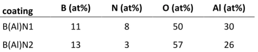
According to EDS analysis after the oxidation test at 800 °C, before being embedded in resin, the oxide scale formed at the coating surface is mainly made of alumina (Tab. 4).
coating B (at%) N (at%) O (at%) Al (at%)
B(Al)N1 11 8 50 30
B(Al)N2 13 3 57 26
Tab. 4 Atomic concentrations obtained by EDS on the surface of coatings B(Al)N1 and B(Al)N2 after oxidation
under wet air (10 kPa H2O, 70 kPa N2, 20 kPa O2) for 4h30 at 800 °C and 1h15 at 1000 °C respectively (± 1, at% margin of error).
After oxidation/corrosion at 800 °C, the observation of the coating in cross-section was done after embedding in resin and polishing. This observation was difficult due to a severe debonding occurring during polishing, apparently between the intact layer and the oxide layer. However, the thickness of the latter is estimated to be 1 to 2 µm. EDS analyses of this oxide layer reveal the significant presence of carbon. This result reveals that the epoxy resin has infiltrated this layer during the preparation prior to polishing. Further, this kind of oxide is known to remain a little porous and to absorb H2O and CO2 at room temperature. The formed oxide layer is not thick enough to become an efficient diffusion barrier and does not prevent the consumption of the coating underneath. Then, the decrease in mass
0 1 2 3 4 0 -0.2 -0.4 -0.6 -0.8 ∆ m /S (m g.c m -2 ) time (h)
11
loss rate that occurs after 2 hours is attributed to the thickening and formation of a continuous alumina scale, and consequently to a slight slowdown in the diffusion of oxidizing species toward the surface. The remaining intact coating has a chemical composition very close to that initially measured, although the proportion of oxygen is slightly higher after oxidation (8 at% instead of 2-3 at%). Thus, the oxidation front can be considered relatively homogeneous.
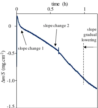
The oxidation/corrosion test of the second B(Al)N sample (referred to as B(Al)N2, deposited under the same conditions as B(Al)N1), was carried out at 1000 °C. Two changes in slope are visible on the plot, with a similar slowdown of the mass loss rate at the end of the test (Fig. 6). The first slope is attributed to the oxidation of a residue of carbon glue, used to fix the substrates to their support in the CVD reactor (carbon oxidizes rapidly and actively at this temperature). Despite efforts to remove this glue before the oxidation tests, a small amount may remain on the surface of the sample. Following the first change in slope, by analogy with pure BN oxidation, the mass variation results from a competition between absorption of hydrated species and oxidation of the coating. The second change in slope may then be a sign that the coating is saturated with hydrated species, and the mass variation is then only due to the oxidation of the coating. Finally, the subsequent gradual lowering of the mass loss rate could be due to the development of a more protective oxide scale.
Fig. 6 Specific mass variation of B(Al)N2 coating (~10 µm thick) on a flat substrate in wet air (10 kPa H2O, 70 kPa N2, 20 kPa O2) at 1000 °C (Oxidation/corrosion perpendicular to the basal planes)
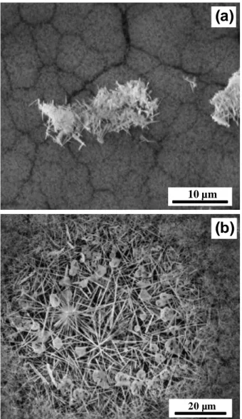
After the oxidation/corrosion test at 1000 °C, the morphology of the surfaced coating has changed significantly (Fig. 7). The surface is composed of acicular crystals, of more or less large dimensions depending on the observed areas. The chemical composition of these crystals obtained by EDS corresponds to that of the compound Al4B2O9 (Tab. 4).
0 0.5 1 slope change 1 slope change 2 slope gradual lowering 0 -1.5 -1.0 -0.5
∆
m
/S
(m
g.c
m
-2)
time (h)
12
Fig. 7 SEM observations of coating B(Al)N2 surface after oxidation under wet air (10 kPa H2O, 70 kPa N2, 20 kPa O2) for 1h15 at 1000 °C showing (a) small and (b) large crystals of compound Al4B2O9
The formation of Al4B2O9 crystals by reaction between B2O3 and Al2O3 allows the retention of part of the B2O3 formed during the oxidation of B(Al)N2. At temperature higher than around 900°C, the formation of Al4B2O9 is known to occur since the reaction rate between B2O3 and Al2O3 becomes upper than the volatilization rate of B2O3 [25]. However, these acicular crystals form a porous and non-uniform layer which does not effectively act as a diffusion barrier and does not prevent consumption of the B(Al)N coating underneath. Although the addition of 9 at% aluminium to boron nitride does not provide effective protection (at least on an extended surface coating), the specific mass loss recorded for B(Al)N at 1000 °C is nevertheless lower than that of BN1 at 800 °C.
10 µm
(a)
20 µm
13
3.2 SiC/BN/SiC and SiC/B(Al)N/SiC multilayer coatings on cellular substrates
3.2.1 Thick BN coatings (oxidation/corrosion parallel to the BN basal planes)
In this section, only BN1 and BN4 coatings are considered, since these coatings have the most different oxidation/corrosion behaviours in the direction perpendicular to the basal planes. Here, the mass variation due to oxidation/corrosion of BN is linked to a front propagation parallel to the basal planes and is related to the cross-section of the BN coating.
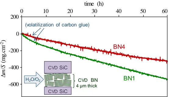
In both cases, a linear mass loss as a function of time is measured during the oxidation tests, but with a slight decrease in slope at the end of the test for the multilayer coating containing BN4 (Fig. 8). SEM observations have shown that localized spalling of the outer layer of SiC occurred on the latter material during the preliminary manual polishing step to prepare the sample prior to oxidation. These spalls are responsible for the non-linearity of the TGA curve. In addition, the calculations show that the mass loss is not in agreement with the lengths of recession measured from the SEM observations shown hereafter. It is overestimated from the TGA data, since an extended area of BN becomes locally exposed where spalling has occurred. Hence subsequently, only recession results obtained from SEM observations in areas without spalling were taken into account. Furthermore, for each curve, a slightly faster mass loss is also visible at the beginning of the test, again due to the rapid volatilization of residual carbon glue from the substrate surface. For the following multilayer coatings, a moderate heat treatment at 500 °C under ambient air of the samples allowed a more efficient removal of these carbon glue residues.
Fig. 8 Specific mass variation of multilayer coatings SiC/BN1/SiC and SiC/BN4/SiC on cellular substrates in wet
air (10 kPa H2O, 70 kPa N2, 20 kPa O2) at 800 °C (oxidation/corrosion parallel to the BN basal planes). BN thickness: 4 µm. Surface exposed: 1 x 10⁻³ cm2 for BN1 and 7 x 10⁻⁴ cm2 for BN4.
After oxidation/corrosion at 800 °C, oxidation fronts could be identified in different areas. Regardless of the area observed, a clear delineation between the intact boron nitride and the epoxy resin is evident (Fig. 9). No traces of oxide were detected and during the mounting of the sample the resin has fully filled the gap left by boron nitride recession. Clear oxidation fronts are observed regardless of the boron nitride crystallization degree (BN1 or BN4, observation not shown for BN4).
CVD SiC CVD SiC H2O/O2 CVD BN 4 µm thick
0
-600
-400
-200
200
(volatilization of carbon glue)
BN1
0
10
20
30
40
50
60
time (h)
∆
m
/S
(m
g.c
m
-2)
BN4
14
Fig. 9 SEM observation of an oxidation front in multilayer coating SiC/BN1/SiC after oxidation under wet air
(10 kPa H2O, 70 kPa N2, 20 kPa O2) for 60 h at 800 °C
EDS maps show even more clearly the boundary between the intact boron nitride layer (high signal levels of boron and nitrogen) and the epoxy resin (high carbon level). A slight excess of oxygen is detected at the interfaces between the silicon carbide layers and the epoxy resin layer (i.e. initially the gap left by BN recession). Similarly, excesses of oxygen and silicon, although more tenuous, are detected at the oxidation front (Fig. 10). It thus seems that a significant quantity of silica covers the SiC surfaces left exposed by the disappearance of BN, and that a small quantity is also present at the oxidation front. However, the produced silica layer is likely to be too thin to act as a diffusion barrier against oxidizing species at high temperature and to slow down the consumption by oxidation/corrosion of the boron nitride layer.
20 µm
cutting
edge
side
oxidation front
CVD
SiC
CVD
SiC
CVD
BN1
sintered SiC
H2O/O2epoxy resin
15
Fig. 10 SEM image and corresponding EDS map analysis of the oxidation front in multilayer coating SiC/BN1/SiC
after oxidation under wet air (10 kPa H2O, 70 kPa N2, 20 kPa O2) for 60 h at 800 °C
This sample configuration made it possible to measure the length of boron nitride recession from the initially polished section to the oxidation front. The consumption rates kBN cons // are considered constant as a function of time and were directly extracted from these SEM observations (Tab. 3). The oxidation rates in the direction parallel to the basal planes of BN1 (the least organized) and BN4 (one of the best organized boron nitrides) are respectively about 4 and 22 times higher than perpendicular to them. Further, compared to BN4, the oxidation rate of BN1 is about 5 times higher parallel to the basal planes of BN (kBN1 cons // ≈ 5 x kBN4 cons //) and 30 times higher perpendicular to them (kBN1 cons ≈ 30 x kBN4 cons ). These results clearly show that: (i) the oxidation/corrosion rate of BN at 800 °C is anisotropic, especially as the crystallization degree of BN is high and (ii) the intrinsic oxidation/corrosion resistance of BN depends on the degree of crystallization, especially in the direction perpendicular to the basal planes and less in the parallel direction.
3.2.2 Thin BN coatings
In this configuration, the thickness of the coating is reduced to ~0.5 µm typical of an interphase in a composite. In the case of pure boron nitride, the oxidation/corrosion rate parallel to the basal planes depending only slightly on the degree of crystallization, only the oxidation of BN1was tested.
After the test at 800 °C, SEM observation shows that the cutting edge surface, i.e. the section exposed to the oxidizing flux, has a gap in place of the boron nitride layer after oxidation (Fig. 11a (insert)). A thin silica layer covers the silicon carbide CVD coatings and the sintered SiC substrate. Longitudinal observation of this sample (i.e. perpendicular to the cutting edge surface) shows the oxidation front with the local presence of a vitreous seal (Fig. 11a). EDS analyses indicate that the vitreous seal is mainly composed of silica and does not contain boron. In this sample, only two zones were observable in longitudinal section and the measured mean length of recession of oxidized boron nitride is 25 (± 2) µm after 60 h. This length of recession is reached in only 1 hour in the sample with a 4 µm thick BN
5 µm B N C O Si SiC SiC BN
16
layer with the same microstructure. In a confined space, the presence of silica significantly impacts the oxidation rate of BN. The presence of B2O3, which was certainly difficult to evacuate during the oxidation test due to the confinement, may explain the acceleration of SiC oxidation and the healing evidenced here. However, no trace of B2O3 could be detected although polishing was carried out with an anhydrous lubricant.
After the test at 1000 °C, the surface of the multilayer coating exposed to the oxidizing flux shows a gap partially filled with oxide (and not a completely empty gap as at 800 °C) (Fig. 11b (insert)). After 60 h, the average length of interphase recession is 200 (± 20) µm. A borosilicate-type oxide seal is present over this entire length (Fig. 11b), except at the extreme surface of the sample. The much lower viscosity of the glassy sealing phase explains this higher rate of BN oxidation, despite a more complete filling of the gap left by BN recession. EDS mapping of the oxide indicates that it is composed of silica. Traces of boron are also visible, but the quantities detected cannot be considered significant. However, as pointed out previously, the presence of B2O3 is necessary for the formation of such high amount of silica, by accelerating the oxidation of silicon carbide. B2O3 is also known to volatilise at room temperature in presence of moisture [31] [32].
Fig. 11 Longitudinal section and (inserts) cutting edge surface SEM observations of SiC/BN/SiC multilayer
coatings (BN thickness ≈ 0.5 µm) after oxidation/corrosion in wet air (10 kPa H2O, 70 kPa N2, 20 kPa O2) for 60 h at (a) 800 °C and (b) 1000 °C. 10 µm CVDSiC CVDSiC oxidation front CVDBN SiO2 epoxy resin +gap
epoxy resin sintered SiC cu tt in g e d g e s u rf a ce gap
sintered SiC + SiO2
CVDSiC+ SiO2 5 µm CVDSiC+ SiO2 (a) SiO2 10 µm sintered SiC CVDSiC CVDSiC epoxy resin cu tt in g e d g e s u rf a ce
gap + oxide CVDSiC+ SiO2
CVDSiC+ SiO2
sintered SiC + SiO2
5 µm (b)
17
The specific mass variation curve obtained by TGA at 800 °C shows two linear domains #1 and #2
(Fig. 12a). These two parts are separated by a change in slope, showing an increase in the rate of mass
loss, after about 30 hours of oxidation/corrosion. A slowing down of the mass loss finally occurs at around 50 hours of testing (domain #3). The mass variation due solely to the oxidation of the interphase after 60 hours represents approximately 60% of the overall mass variation recorded before subtracting the contribution of the SiC surface oxidation (i.e. mBN ≈ -0.08 mg).
An analysis of the mass variation curve similar to that of the previous thick coatings on flat substrates can be carried out. Thus, the first linear domain (#1) should correspond to the absorption of hydrated species combined with the active oxidation of BN. Then, the second linear domain (#2) should correspond to the oxidation of BN without protection and quasi-saturated with hydrated species. The transition time of 30 h between these two linear domains has to be compared to that of 30 minfor a flat coating with a thickness limited to about 10 µm. But it should also be considered that, in addition to the different geometrical configuration, the absorption rate is reduced due to the dissolution of a small quantity of SiO2 in the borosilicate at the surface of BN, which limits the access of H2O more deeply into the coating. Finally, in domain #3, with the increasing amount of dissolved SiO2, a silica-enriched borosilicate glass seal is formed at the oxidation front; part of B2O3 volatilizes while the rest is fixed to SiO2. This dissolution leads locally to an acceleration of the oxidation of the silicon carbide. On the other hand, the resulting borosilicate layer acts as a diffusion barrier protecting the BN layer against oxidizing species and the oxidation of the latter is significantly slowed down. Once the borosilicate is saturated with silica, the volatilization of B2O3, as well as the diffusion of oxidizing species, is significantly decreased. With the limited but not stopped volatilization of B2O3, the saturation limit is exceeded and SiO2 precipitates. The protective effect of this seal will then a priori only increase with time. These different steps are represented by diagrams in Fig. 12a.
At 1000 °C, the TGA curve still shows two different linear domains #1 and #2 (Fig. 12b). A slowdown in the mass loss rate with slope change occurs after only about 5 hours of oxidation/corrosion. After 60h, the mass variation of the interphase due solely to oxidation in wet air represents about 30% of the overall mass variation recorded (before subtracting the contribution of the SiC surface oxidation) (i.e. mBN ≈ -0.14 mg).
The slowdown in mass loss after 5 hours of testing appears to be related to the formation of the oxide seal between the two SiC layers as illustrated in the diagrams in Fig. 12b. However, compared to oxidation at 800 °C, the healing effect provided by the seal formation seems less efficient. At 1000°C, its viscosity is so low that its presence does not prevent the continuous recession of the boron nitride layer, even though the borosilicate forms a continuous oxide seal in the gap. As the temperature rises, the borosilicate is less and less able to limit the diffusion of oxidizing species, despite an increase in its ability to dissolve SiO2 [33]. The linear evolution of the mass loss in domain #2 of the TGA curve at 1000 °C is characteristic of a steady-state oxidation regime of the BN interphase.
Considering an BN oxidation activation energy of about 100 kJ.mol-1, the recession length of 200 µm at 1000 °C after 60 h is consistent with that of 25 µm at 800 °C after 60 h. Given the operating temperatures above 1000 °C required for the applications targeted in aircraft engines, the use of a pure boron nitride interphase does not seem adequate to achieve the desired service life of 50,000 hours.
18
Fig. 12 Specific mass variations of multilayer coatings SiC/BN1/SiC (BN1 thickness ≈ 0.5 µm) on cellular substrates
in wet air (10 kPa H2O, 70 kPa N2, 20 kPa O2) at (a) 800 °C and (b) 1000 °C with schematic representations of the different oxidation/corrosion steps
3.2.3 Thin B(Al)N coatings
For the oxidation/corrosion of the SiC/B(Al)N/SiC multilayer model samples, the same composition of B(Al)N as for the oxidation tests on flat coatings was retained (9 at% Al). The crystallization degree of the BN portion of these coatings is equivalent to that of BN1, so they should exhibit quasi-isotropic reactivity. Thus, only the "interphase" configuration (thin thickness of about 0.5 µm) was considered for B(Al)N. -2000 -1800 -1600 -1400 -1200 -1000 -800 -600 -400 -200 0 0 10 20 30 40 50 60 time (h) ∆ m /S (m g.c m -2) sintered SiC CVDSiC CVDSiC BN (SiO2+ B2O3)(l) HxByOz SiO2 SiO2 sintered SiC CVDSiC CVDSiC BN SiO2 HxByOz SiO2(s)+ (SiO2,B2O3) (l) SiO2 domain #1 domain #2 0 -800 -600 -400 -200 200 0 10 20 30 40 50 60 time (h) ∆ m /S (m g.c m -2) sintered SiC CVDSiC CVDSiC BN BN OH HxByOz SiO2 SiO2 sintered SiC CVDSiC CVDSiC BN B2O3+ δSiO2 HxByOz SiO2 BNOH domain #1 domain #2 sintered SiC CVDSiC CVDSiC BN HxByOz SiO2(s)+ (SiO2,B2O3) (l) SiO2 domain #3
(a)
(b)
19
After oxidation/corrosion at 800 °C, a gap has replaced the B(Al)N coating on the side exposed to the oxidizing species during the test. This behaviour remains similar to previous tests with a thin pure BN coating. A thin silica scale covers the adjacent surfaces of CVD-deposited silicon carbide and the sintered substrate. In addition, large silica clusters are present on the cutting edge surface of the sintered silicon carbide close to the interphase (Fig. 13a (insert)). These clusters are not observed after oxidation of the SiC/BN/SiC multilayer materials, regardless of the thickness of the boron nitride layer. The oxidation front has no glassy oxide seal in longitudinal section (Fig. 13a). Only few solid particles are visible in the gap left by the interphase recession. According to EDS analyses, these particles are predominantly alumina. No silica is detected by EDS (maps not shown). The average length of interphase recession through the material is about 115 (± 15) µm, which is 4 to 5 times longer than for pure boron nitride. The absence of silica throughout the gap left by the interphase recession combined with the presence of SiO2 clusters on the silicon carbide surface exposed to the oxidizing flux suggests that: (i) the alumina in contact with the silicon carbide enhances the protective effect of the little silica formed on the SiC surface and (ii) the residual liquid boron oxide has flowed out of the multilayer coating during the oxidation test, without chemical interactions with silica. Indeed, the large amount of silica present on the outer SiC surface exposed to the oxidizing flux could only be formed in contact with liquid B2O3, since it was verified that under these test conditions used, the silica scale should be extremely thin (~40 nm). Moreover, a strong wetting of B2O3 on alumina has already been observed in previous work [25]. In the model materials considered here, some of the boron oxide formed is volatilized in the presence of moisture while the other part appears to migrate along the alumina-covered walls between the two SiC layers and is "rejected" on the outer surface of the multilayer coating. Finally, the silica clusters seem to be localized on the CVD deposited silicon carbide on the side of the sintered SiC substrate (i.e. 1st SiC layer).
After testing at 1000 °C and unlike oxidation/corrosion at 800 °C, the surface of the multilayer coating exposed to the oxidizing flux does not show any silica cluster on the silicon carbide. The area corresponding to the oxidized interphase shows an oxide bead, not an empty gap (Fig. 13b (insert)). Within the multilayer coating, the length of interphase recession is limited to 15 (± 2) µm (3 measured areas). An oxide seal is present along this length in the longitudinal section (Fig. 13b). Compared to oxidation at 800 °C after the same aging time (60h), the healing resulting from the formation of this seal has reduced the length of B(Al)N interphase recession by a factor of about 8. EDS analysis of the seal reveals that it is composed of silica and alumina (maps not shown). Although it has been previously verified that the oxidation conditions used lead to the formation of crystals of the compound Al4B2O9, boron is not detected within the seal. The presence of silica in the oxide mixture could lower the kinetics of Al4B2O9 crystal formation [25]. The analysis technique used (EDS) is also likely not sufficiently accurate and local to detect boron in small quantities in such a small space.
20
Fig. 13 Longitudinal section and (inserts) cutting edge surface SEM observations of SiC/B(Al)N/SiC multilayer
coatings (B(Al)N thickness ≈ 0.5 µm) after oxidation/corrosion in wet air (10 kPa H2O, 70 kPa N2, 20 kPa O2) for 60 h at (a) 800 °C and (b) 1000 °C.
At 800 °C, the TGA curve again shows two domains, #1 and #2 (Fig. 14a). In domain #1, the mass loss versus time is almost linear, then the mass variation becomes zero after a sufficiently long time (after about 38 hours of testing) in domain #2. For this sample, the mass variation due solely to interphase oxidation represents about 30% of the overall mass variation recorded (before subtracting the contribution of the SiC surface oxidation) (i.e. mB(Al)N ≈ -0.037 mg). The linear regime of domain #1 is the result of two opposite contributions: (i) a mass gain related to silica and alumina formations and (ii) the mass loss related to B2O3 volatilization. It has been shown, using flat B(Al)N coatings, that the alumina formed by oxidation of this material under these conditions is porous. The interconnected porosity of the alumina becomes: (i) a large pathway to oxidizing species diffusion and (ii) an extended surface easy wetted by the liquid B2O3 causing its rejection by capillary effect. This rejection results in the absence of a silica seal in the gap and the presence of silica clusters on the outer surface produced by accelerated oxidation of SiC in contact with B2O3. From a certain length (115 µm), the interconnection of the porosity is no longer sufficient, which strongly limits the access of oxidative/corrosive species (O2/H2O) to the interphase and a stabilized regime is reached in domain #2. In this latter domain, the stabilization of the mass would not be due to a healing but to the accelerated formation of SiO2 (in addition to Al2O3) which compensates for the small loss of the interphase. This oxidation scenario has already been observed on CMC SiBC multilayer matrix sections [34]. It is schematically illustrated in Fig. 14a along the TGA curve.
SiO2+ Al2O3 CVDB(Al)N oxidation front sintered SiC CVDSiC CVDSiC 5 µm c u tt in g e d g e s u rf a c e epoxy resin
sintered SiC + SiO2
oxide CVDSiC+ SiO2 CVDSiC+ SiO2 5 µm gap + Al2O3 CVDB(Al)N oxidation front CVDSiC 5 µm sintered SiC CVDSiC cutting edge side H2O /O2 gap CVDSiC + SiO2 SiO2 CVDSiC+ SiO2 5 µm sintered SiC + SiO2
(b) (a)
21
The TGA curve obtained at 1000 °C is very noisy since the mass variation due to interphase oxidation represents only 4% of the overall mass variation recorded (before subtracting the contribution of the SiC surface oxidation) (i.e. mB(Al)N ≈ -0,015 mg), but its analysis remains possible. It again shows different domains (Fig. 14b). Three quasi-linear parts can be distinguished, with two successive changes in slope indicating a strong slowdown in the mass loss rate. The mass of the sample becomes almost constant as a function of time in the last domain (#3) (after about 22 hours of oxidation/corrosion); a strong limitation of the oxidation of the interphase must be the cause. This limitation is in accordance with the limited measured interphase recession length (15 (± 2) µm). It is explained by the increase in the quantity of alumina formed. On the one hand, the capillary force between B2O3 and Al2O3 can contribute to limit the volatilization of HxByOz. The formation of a thin scale of B2O3 is therefore allowed because the rate of volatilization becomes lower than the rate of formation [35]. On the other hand, B2O3 is no longer rejected towards the outer surface of the material as it is at 800°C. The diffusion of oxygen is limited by the B2O3 scale and the porous alumina layer, the growth of which helps to slightly reduce the width of the diffusion path, making protection more effective [36] [37] [38]. At 1000 °C, the mixture of oxides formed at the oxidation front (borosilicate, alumina and, possibly, aluminium borate crystals Al4B2O9 as observed on flat coatings under the same oxidation conditions) play an effective role as a diffusion barrier.
Fig. 14 Specific mass variations of multilayer coatings SiC/B(Al)N/SiC (B(Al)N thickness: 0.5 µm) on cellular
substrates in wet air (10 kPa H2O, 70 kPa N2, 20 kPa O2) at (a) 800 °C and (b) 1000 °C with schematic representations of the different oxidation/corrosion steps
time (h) 0 -800 -600 -400 -200 ∆ m /S (m g .c m -2) 0 10 20 30 40 50 60 sintered SiC CVDSiC CVDSiC HxByOz SiO2 SiO2 Al2O3 B(Al)N sintered SiC CVDSiC CVDSiC HxByOz SiO2 SiO2 B(Al)N Al2O3 B2O3 domain #1 domain #2 time (h)
(a)
-200 -100 0 1000 10 20 30 40 50 60 ∆ m /S (m g .c m -2) sintered SiC CVDSiC CVDSiC HxByOz SiO2 Al2O3 (B 2O3, SiO2) (l) B(Al)N sintered SiC CVDSiC CVDSiC HxByOz SiO2 SiO2 Al2O3 SiO 2(s)+ (SiO2,B2O3) (l) B(Al)N sintered SiC CVDSiC CVDSiC HxByOz SiO2 SiO2 Al2O3 SiO2(s)+ (SiO2,B2O3) (l) B(Al)N domain #2 domain #1 domain #3(b)
22
4. Conclusion
This work allowed quantifying the influence of different physical and chemical characteristics of turbostratic boron nitride-based CVD coatings on their resistance to oxidation in wet air, at high temperature (800 and 1000 °C).
It was thus verified on thick coatings that the oxidation/corrosion rate of BN at 800 °C is anisotropic, especially as the degree of crystallization of BN is high. When boron nitride is exposed perpendicular to its basal planes, its crystallization degree has a strong impact on its oxidation resistance. Firstly, the variation in the inter-reticular distance d is the major parameter that controls the BN consumption rate by oxidation/corrosion at high temperature. A variation in d leads to a high variation in the oxidation/corrosion resistance: the consumption rate being multiplied by a factor of up to 30 between a BN coating deposited at 900 °C with d = 0.343 nm and a BN coating deposited at 1200-1400 °C with d = 0.336 nm close to the theoretical value of h-BN. Secondly, for the materials with the best crystallization degrees in this work, the oxidation/corrosion resistance of BN increases with the mean value of the coherence length Lc (at η identical, η = 0.5) or with the structural homogeneity η (for the highest Lc, Lc = 10-12 nm). This seems to be associated with an increased absorption of moisture as Lc decreases. In the case of not very homogeneous coatings, a preferential consumption of the poorly organized areas is observed.
The oxidation rate dependence of BN on its crystallization degree is much less pronounced in the direction parallel to the basal planes. When the difference is a factor of 30 in the perpendicular direction, it is only a factor of 5 in the other direction. Thus, given that the main oxidation direction of the BN interphase in CMCs (for aircraft engines) corresponds to the direction parallel to the basal planes (at a matrix crack deflected by the interphase or at a cutting edge of a workpiece), maximising its crystallisation degree does not appear to be the best solution for significantly increasing its resistance to oxidation in the presence of moisture at high temperature.
It was possible to simulate the case of interphases in CMCs by oxidizing thin boron nitride layers (thickness ~0.5 µm) in multilayer SiC/BN/SiC coatings. In such confined gap between the two SiC layers, the formation of a borosilicate-type oxide is observed at the oxidation front. This glass leads to a limitation of the oxidation species diffusion. The decrease in its efficiency when the temperature increases from 800 to 1000 °C is related to the lowering of the viscosity of these glassy phases. A steady oxidation of the boron nitride layer is then evidenced and the behaviour is not satisfactory.
When aluminium is introduced into the layer of boron nitride (at about 9 at%), two different situations arise depending on the temperature. At 800 °C, the oxidation/corrosion of a thin layer (~0.5 µm) of B(Al)N in multilayer SiC/B(Al)N/SiC coatings results in the formation of porous alumina and liquid B2O3 is rejected out of the gap by capillary effect. The mere presence of porous alumina in the path of the oxidizing species in the multilayer coating only poorly limits their diffusion towards the intact B(Al)N coating, as also observed on thick flat coatings. At 1000 °C, the oxidation/corrosion of this type of material gives rise to the formation of a mixture of oxides (borosilicate, alumina and, possibly, crystals of aluminium borate Al4B2O9 as on flat coatings under identical oxidation conditions) on the oxidation front. This mixture of oxides seems in this case to act efficiently as a diffusion barrier, resulting in a marked slowing down of the oxidation of the material. The healing efficiency evidenced at a constant temperature of 1000 °C makes B(Al)N interesting as a CMC interphase for applications in extreme operating conditions.
Further work is now required to better characterize the material by applying thermal cycles during oxidation. Moreover, above 1200 °C, the expected compound in the Al2O3-B2O3 system becomes Al18B4O33 (instead of Al4B2O9). Although the structure of these crystals is very close to that of the Al4B2O9 compound, oxidation tests at even higher temperatures (e.g. 1300 °C) would provide insight into the influence of this compound on the ability of the oxide mixture to protect the material. If the oxidation protection remains effective under all conditions, the ability of B(Al)N with 9 at% of aluminium to act as a mechanical fuse should be verified. If so, lifetime tests of composites under mechanical loading may be considered.
23
Acknowledgements
This work was supported by SAFRAN CERAMICS through a PhD grant given to P. Carminati.
References
[1] J. Steibel, Ceramic matrix composites taking flight at GE Aviation, Am. Ceram. Soc. Bull., 98 [no. 3] (2019) 30–33,
https://ceramics.org/wp-content/uploads/2019/03/April-2019_Feature.pdf
[2] R. Naslain, Design, preparation and properties of non-oxide CMCs for application in engines and nuclear reactors: an overview, Compos Sci Technol 64 (2004) 155–170,
https://doi.org/10.1016/S0266-3538(03)00230-6
[3] L. Longbiao, 5.3 Advanced SiC/SiC Composite Systems, Comprehensive Composite Materials II, 5 (2018) 41-85, https://doi.org/10.1016/B978-0-12-803581-8.09989-6
[4] F. Rebillat, A. Guette, L. Espitalier, C. Debieuvre, R. Naslain, Oxidation resistance of SiC/SiC micro and minicomposites with a highly crystallised BN interphase, J. Eur. Ceram. Soc. 18 (1998) 1809– 1819, http://dx.doi.org/10.1016/S0955-2219(98)00120-4
[5] J. Huang, C. Pan, D. Lii, Investigation of the BN films prepared by low pressure chemical vapor deposition, Surf. Coat. Technol. 122 (1999) 166-175,
https://doi.org/10.1016/S0257-8972(99)00306-0
[6] S. Jacques, A. Lopez-Marure, C. Vincent, H. Vincent, J. Bouix, SiC/SiC minicomposites with structure-graded BN interphases, J Eur. Ceram. Soc. 20 (2000) 1929-1938,
https://doi.org/10.1016/S0955-2219(00)00064-9
[7] P. Carminati, T. Buffeteau, N. Daugey, G. Chollon, F. Rebillat, S. Jacques, Low pressure chemical vapour deposition of BN: Relationship between gas phase chemistry and coating microstructure, Thin Solid Films 664 (2018) 106-114, https://doi.org/10.1016/j.tsf.2018.08.020
[8] J. Dai, Y. Wang, Z. Xu, R. Mu, L. He, Effect of temperature on the growth of boron nitride interfacial coatings on SiC fibers by chemical vapor infiltration, Ceram. Int. 45 (2019) 18556-18562, https://doi.org/10.1016/j.ceramint.2019.06.077
[9] A.G. Evans, F.W. Zok, T.J. Mackin, High temperature mechanical behaviour of ceramic composites, in: S.V. Nair, K. Jakus (Eds.), High Temperature Mechanical Behavior of Ceramic Composites, 1 Butterworth-Heinemann Elsevier Ltd, Oxford, United Kingdom, (1995) 3–84,
http://dx.doi.org/10.1016/B978-075069399-8/50002-5
[10] R. Naslain, R. Pailler J. Lamon, Single- and multilayered interphases in SiC/SiC composites exposed to severe environmental conditions: an overview, Int. J. Appl. Ceram. Technol. 7 (2010) 263–275, https://doi.org/10.1111/j.1744-7402.2009.02424.x
[11] L.G. Podobeda, A.K. Tapsuk, A.D. Buravov, Oxidation of boron nitride under nonisothermal conditions, Powder Metall. Met. Ceram. 15 (1976) 696-698,
http://dx.doi.org/10.1007/BF01157838
[12] E.J. Opila, R. E. Hann, Jr., Paralinear oxidation of CVD SiC in water vapor; J. Am. Ceram. Soc. 80 (1997) 197–205, https://doi.org/10.1111/j.1151-2916.1997.tb02810.x
[13] N. S. Jacobson, S. Farmer, A. Moore, H. Sayir, High-temperature oxidation of boron nitride: I, monolithic boron nitride, J. Am. Ceram. Soc. 82 (1999) 393-398,
https://doi.org/10.1111/j.1551-2916.1999.tb20075.x
[14] L.U.J.T. Ogbuji, A pervasive mode of oxidative degradation in a SiC–SiC composite, J. Am. Ceram. Soc. 81 (1998) 2777-2784, https://doi.org/10.1111/j.1151-2916.1998.tb02696.x
24
[15] H. Hatta, T. Sohtome, Y. Sawada, A. Shida, High temperature crack sealant based on SiO2-B2O3 for SiC coating on carbon-carbon composites, Adv. Composite Mater. 12 (2003) 93-106,
https://doi.org/10.1163/156855103772658498
[16] L. Quemard, F. Rebillat, A. Guette, H. Tawil, C. Louchet-Pouillerie, Degradation mechanisms of a SiC fiber reinforced self-sealing matrix composite in simulated combustor environments, J. Eur. Ceram. Soc. 27 3 (2007) 77-388, https://doi.org/10.1016/j.jeurceramsoc.2006.02.042
[17] F. Rebillat, E. Garitte, A. Guette, Quantification of higher SiC fiber oxidation rates in presence of B2O3 under air, in: D. Singh, D. Zhu, Y. Zhou, M. Singh (Eds.) Design, Development, and Applications of Engineering Ceramics and Composites: Ceramic Transactions, 215 (2010) 135-149, https://doi.org/10.1002/9780470909836.ch13
[18] B. Mcfarland, E.J. Opila, Silicon carbide fiber oxidation behavior in the presence of boron nitride, J. Am. Ceram. Soc. 101 (2018) 5534-5551, https://doi.org/10.1111/jace.15807
[19] G.N. Morscher, Tensile stress rupture of SiCf/SiCm minicomposites with carbon and boron nitride interphases at elevated temperatures in air, J. Am. Ceram. Soc. 80 (1997) 2029-2042,
https://doi.org/10.1111/j.1151-2916.1997.tb03087.x
[20] G.N. Morscher, D.R. Bryant, R.E. Tressler, Environmental durability of BN‐based interphases (for SiCf/SiCm composites) in H2O containing atmospheres at intermediate temperatures, Ceram. Eng. Sci. Proc. 18 (1997) 525-534, https://doi.org/10.1002/9780470294437.ch58
[21] H. Yang, Z. Lu, B. Bie, Z. Fu, J. Yue, X. Huang, Microstructure and damage evolution of SiCf/PyC/SiC and SiCf/BN/SiC mini-composites: A synchrotron X-ray computed microtomography study, Ceram. Int. 45 (2019) 11395-11402, https://doi.org/10.1016/j.ceramint.2019.03.004
[22] O.G. Diaz, K. Marquardt, S. Harris, L. Gale, L. Vandeperre, E. Saiz, F. Giuliani, Degradation mechanisms of SiC/BN/SiC after low temperature humidity exposure, Available at SSRN:
https://ssrn.com/abstract=3509315 or http://dx.doi.org/10.2139/ssrn.3509315
[23] F.W. Zok, P.T. Maxwell, K. Kawanishi, E.B. Callaway, Degradation of a SiC‐SiC composite in water vapor environments, J. Am. Ceram. Soc. 103 (2020) 1927-1941,
https://doi.org/10.1111/jace.16838
[24] G.N. Morscher, F. Hurwitz, H.M. Yun, High temperature Si‐doped BN interphases for woven SiC/SiC composites, Ceram. Eng. Sci. Proc. 23 (2002) 295-302,
https://doi.org/10.1002/9780470294741.ch34
[25] K. Grente, S. Bertrand, F. Rebillat, F. Langlais, F. Lamouroux, Réalisation de matériaux composites à matrice céramique ayant une tenue améliorée à haute température sous atmosphère corrosive, Patent, France n° 04 11262, 22/10/2004, FR2877016 (A1); FR2877016 (B1), internationale classification C23C16/06, C04B35/01, C23C16/22
[26] E. Opila, Influence of alumina reaction tube impurities on the oxidation of Chemically-Vapor-Deposited silicon carbide, J. Am. Ceram. Soc. 78 (1995) 1107-1110,
https://doi.org/10.1111/j.1151-2916.1995.tb08449.x
[27] S. Willemin, P. Carminati, S. Jacques, J. Roger, F. Rebillat, Identification of complex oxidation/corrosion behaviours of boron nitride under high temperature, Oxid. Met. 88 (2017) 247-256, https://doi.org/10.1007/s11085-017-9739-z
[28] R.S. Pease, An X-ray study of boron nitride, Acta Cryst. 5 (1952) 356-361,
https://doi.org/10.1107/S0365110X52001064
[29] N.S. Jacobson, D.S. Fox, E. J. Opila, High temperature oxidation of ceramic matrix composites, Pure & Appl. Chem. 70 (1998) 493-500, https://doi.org/10.1351/pac199870020493
[30] C.G. Cofer, J. Economy, Oxidative and hydrolytic stability of boron nitride – A new approach to improving the oxidation resistance of carbonaceous structures, Carbon 33 (1995) 389-395,
http://dx.doi.org/10.1016/0008-6223(94)00163-T
[31] T. Matsuda, Stability to moisture for chemically vapour-deposited boron nitride, J. Mater. Sci. 24 (1989) 2353-2357, https://doi.org/10.1007/BF01174496
[32] S. Le Gallet, F. Rebillat, A. Guette, R. Naslain, Stability of BN coatings processed from BCl3-NH3-H3 gas mixture, High Temperature Ceramic Matrix Composites (W. Krenkel, R. Naslain, H.
25
Schneider, eds), Wiley-VCH, Weinheim et New York (2001) 187-192,
https://doi.org/10.1002/3527605622.ch30
[33] T.J. Rockett, W.R. Foster, Phase relations in the system boron oxide-silica, J. Am. Ceram. Soc. 48 (1965) 75-80, https://doi.org/10.1111/j.1151-2916.1965.tb11803.x
[34] M. Herbreteau, Caractérisation et modélisation de la progression de l'oxydation autour d'un défaut d’impact à haute température d’un matériau composite à matrice céramique, phD Thesis, University of Bordeaux, 2016
[35] C.S. Tedmon, Jr., The effect of oxide volatilization on the oxidation kinetics of Cr and Fe-Cr alloys, J. Electrochem. Soc. 113 (1966) 766-768, https://doi.org/10.1149/1.2424115
[36] D.W. McKee, Oxidation protection of carbon materials, Science of Carbon Materials, Editors H. Marsh and F. Rodríguez-Reinoso, Universidad de Alicante, Chap. 12 (2000)
[37] J. Schlichting, Oxygen transport through silica surface layers on silicon-containing ceramic materials, High Temp High Press 14 (1982) 717-724,
http://pascal-francis.inist.fr/vibad/index.php?action=getRecordDetail&idt=9409680
[38] J. Schlichting, Oxygen transport through glass layers formed by a gel process, J. Non Cryst Solids 63 (1984) 173-181, https://doi.org/10.1016/0022-3093(84)90396-X