Design and Implementation of Software
to Automate Reuse in
Component-Based System Engineering
byChibong Chan
Submitted to the Department of Electrical Engineering and Computer Science in Partial Fulfillment of the Requirements for the Degrees of
Bachelor of Science in Electrical Engineering and Computer Science and Master of Engineering in Electrical Engineering and Computer Science
at the Massachusetts Institute of Technology
r MASSACHUSETTS INSTrTUTE
August 17, 2004 L<ePtleer 20o4 OF TECHNOLOGY
Copyright 2004 Chibong Chan. All rights reserved. 1
LIBRARIES
The author hereby grants to M.I.T. permission to reproduce and distribute publicly paper and electronic copies of this thesis
and to grant others the right to do so.
Author
-Department of Elecz cal Engineering and Computer Science
August 17, 2004 Cd C Certified by Accepted b. - " ...=--~-~' ' Nancy G. Leveson .fw-~-~--~~ ~Professor
//oo
j
/'
~--
v
~
Thesis
Supervisor
- '~Arthur C. Smith Chairman, Department Committee on Graduate Theses
ARCHIVES ,
Design and Implementation of Software to Automate Reuse in
Component-Based System Engineering
by
Chibong Chan
Submitted to the
Department of Electrical Engineering and Computer Science August 17, 2004
In Partial Fulfillment of the Requirements for the Degree of Bachelor of Science in Electrical Engineering and Computer Science and Master of Engineering in Electrical Engineering and Computer Science
ABSTRACT
The goal of this thesis is to develop software under the SpecTRM software package for the partial automation of tasks associated with reusing SpecTRM-RL component models. The automation software is designed to aid the application of component-based system engineering in SpecTRM, mainly by reducing the amount of manual work necessary in setting up component models for simulation. My thesis will examine the properties of component models, and the common tasks associated with component-based system engineering, so as to identify areas where automation is possible, and then present the user interfaces and algorithms necessary to achieve automation. The automation software will be implemented in Java under the Eclipse platform, in order to be seamlessly integrated into the SpecTRM software package.
Thesis Supervisor: Nancy G. Leveson Title: Professor
Acknowledgments
This work was partially supported by funding from EuroControl SafeDesign Project Contract # C/1.394/CEE/NB/03.
Sun, Sun Microsystems, the Sun Logo, Java, and all Java-based marks are trademarks or registered trademarks of Sun Microsystems, Inc. in the United States and other countries. Microsoft Windows is a trademark of Microsoft Corporation in the United States and other countries.
MacOS is a registered trademark of Apple Computer, Inc., in the U.S. and other countries. Linux is a registered trademark of Linus Torvalds.
Table of Contents
1. Introduction 7
1.1. What is SpecTRM? ...7
1.2. What is Component-Based System Engineering (CBSE)? ... 9
1.3. Motiviation and Goal of This Thesis ... 10
2. Automation of Blackbox Model Connections Setup 11 2.1. Overview of Simulation Configuration in SpecTRM . ... 11
2.1.1. The Need for Feedback Conduits ... 12
2.2. Automating Setup of Conduits: an Analysis ... 13
2.2.1. A NaYive Approach ...14
2.2.2. Conduit Setup as a Form of Linking ...15
2.2.3. The Need for a Strictly Followed Naming Scheme ... 16
2.3. A Framework for Automating Conduit Setup ...18
2.3.1. Overview ...18
2.3.2. A Three-Layer Design ...20
2.4. Criteria for Matching Outputs to Inputs ... 22
2.5. Summary ... 26
3. Additional Automation Possibilities 27 3.1. Simulation Configuration as a Blackbox Model ... 28
3.1.1. Design Changes ...29
3.2. Replacing One Model by Another ...31
3.2.1. Design Changes ... 32
3.3. Summary ... 33
4. Implementation 35 4.1. Language and Platform ... 35
4.1.1. What is Eclipse? ... 35
4.1.2. The SpecTRM API ... 37
4.2. Implementation Details and Issues ... 38
4.2.2. The Manager and Matcher Layers ... 40 5. Conclusion 43 5.1. Future Directions ...44 References 45 A. Code 46 A. 1. ConnectionM anagerjava ...46 A .2. SpecTRM M odel.java ...52 A .3. M atchResult.java ... 53
A.4. AbstractM odel.java ... 54
A.5. RLM odel.java ... 55
A.6. SCFM odel.java ...56
A.7. IIOM atcher.java ...58
A.8. IReplaceM atcher.java ...59
A .9. DefaultlOM atcher.java ...60
List of Figures
Figure 1: The structure of an intent specification, from [1] ... 7
Figure 2: sample SpecTRM-RL specification for an input element, from [6] ...12
Figure 3: SpecTRM's simulation configuration editor ... 14
Chapter 1
Introduction
In this thesis, I will discuss the design and implementation of automation software
for automating user tasks related to setting up simulations in the SpecTRM software package. This is done in the larger context of practicing component-based system
engineering, an approach to engineering complex systems that promotes safe reuse of
engineering development efforts.
1.1 What is SpecTRM?
Decomposition
Refinemen
Environment Operator Svstem Components
Figure 1: The structure of an intent specification, from [1].
SpecTRM is a software environment built around a systems engineering methodology of the same name, namely Specificiation Tools and Requirements Methodology. Invented by Professor Nancy Leveson, this methodology revolves around the construction of intent
specifications, a format of writing specifications that strives to promote the recording of
/
Intent
r I I ISystem
,
Purpose ' ' r I System I I Principles ' I I I I Blackbox I IDesign
'
Representation
I,
I Code ' l (Physical ~~~~~~~~~~~~Representation)~~I IRepresentation)
______ I I - -~~~~~decisions at every step and level of system design [1]. As shown in Figure 1, the
structure of an intent specification consists of a number of different levels, which represents different perspectives on a system, such as system purpose, system design principles, blackbox behavior, design representation, and physical representation (code). The primary objective for using intent specifications in system development is to help catch errors early in system design, particularly for systems with software components. Generally speaking, software errors result either from an incorrect implementation that fails to meet specification, or from a correct implementation of a specification in which the behavior specified has unexpected and undesirable consequences, particularly when in interaction with the rest of the system [11, pg. 157]. For safety-critical systems such as airplane autopilots, satellite controllers, and nuclear power plant automations, such software errors may result not only in substantial loss of money, but also something more catastrophic such as loss of life or environmental disaster. Through various organization principles backed by diverse research in systems theory, cognitive psychology, and human-machine interaction, the format, structure and content of intent specifications
strive to promote better human reasoning on the system being specified, in an effort to make the aforementioned types of errors easier and earlier to catch [ 1 ].
Of particular interest for this thesis proposal is the blackbox behavior level of an intent specification. In order for the description of the desired blackbox behavior of the system to be both precise yet human-readable, this level is constructed in SpecTRM using a formal specification language called SpecTRM-RL (SpecTRM Requirements
Language). Using this language, the behavior of a system is described via one or more connected models, where each model can be thought of as a state machine with inputs, either received from an external source or from other models within the system, and outputs to the external environment or to other models. One advantage of using
SpecTRM-RL to describe system blackbox behavior is that because the semantics of the language is based on Mealy finite state machines [3, pg. 8], certain types of analysis and simulation can be run on the resulting system models. This allows the behavior
specification to be verified for a number of correctness and safety related features, such as robustness and completeness [2], before actually implementing a prototype in
1.2 What is Component-Based System Engineering (CBSE)?
As we have just stated, SpecTRM-RL models are used to document a system or system component's blackbox behavior. However, for complex systems such as those found in spacecraft controllers, airplane autopilots, etc., the precise blackbox behavior can be very complex, which makes the construction of SpecTRM-RL models a time-consuming process. To gain more value out of SpecTRM-RL models, one solution is to
follow a system engineering methodology called "component-based system engineering"
(heretofore referred to as CBSE), as proposed in Weiss et al [4]. The methodology is
similar to "based software engineering"; however, whereas in component-based software engineering the aim is to promote reuse of software code to lower
software development costs and shorten development cycles, component based system engineering takes a step further, and attempts to promote the reuse of specifications of the individual components that can be used to build up a system in some particular domain
architecture [5].
As a concrete example, consider the application of component-based system engineering to the domain of spacecraft design, as described in Weiss's master thesis on SPHERES [5]. Despite the myriad variations in the detailed design of spacecraft, all spacecrafts have similar subsystems, such as attitude determination and control, power, thermal, guidance and navigation, communications, and propulsion [4]. Component-based system engineering starts off with such a top-down decomposition of the system being built, then apply system engineering methodologies to the development of the
individual components. For example, under SpecTRM, this would include the
construction of generic intent specifications for each system component, along with their respective SpecTRM-RL models. Once these components are built, the system as a whole is modeled by connecting the component SpecTRM-RL models together
appropriately and running a simulation on them. Because the generic components are fully encapsulated, they can be interconnected differently to yield different designs. Alternatively, for the same particular generic component in a generic spacecraft design, there might be a family of different specific components with similar interface to the
system, but have different underlying behavior model. By creating intent specifications and SpecTRM-RL models for each of them, these different alternatives of system design can be examined by replacing one component in the family with another and running simulations to test the system, all before the building of actual prototypes for these components.
1.3 Motivation and Goal of This Thesis
Currently, SpecTRM has enough functionality to support component-based systems engineering; however, some tasks can be tedious to perform. In particular, to setup a simulation of the system, one must first manually create all the input-output connections between the component models, and then connect all the inputs and outputs that interface with the external environment with the appropriate input data files and output data files. The need to connect component models together of course stems from the system being decomposed into component models during the application of
component-based system engineering. Now, since each component is represented by an
intent specification and a SpecTRM-RL model, both of which are capable of capturing a rich variety of information useful for system engineering, it was thought that perhaps one can somehow make use of that information to create the appropriate inter-component connections automatically. This way, the system can be assembled by simply selecting the components, and they will be able to connect themselves automatically, leading to a more efficient "plug-and-play" environment for building simulations of the system.
Thus, automating the task of connecting component models together will be the main focus of this thesis. Chapter 2 will examine the task of setting up simulations in
detail, in order to come up with the general algorithm and software framework for
automating connections. Chapter 3 will explore other aspects of simulation setup that can be automated, mostly based on variations of connecting models together. Finally,
Chapter 4 will examine the issues involved in implementing the software automation
Chapter 2
Automation of Blackbox Model
Connections Setup
From the start, one major task that occurs in applying CBSE in SpecTRM was identified: setting up the input-output connections between component blackbox models. This task is necessary setup work for simulation of the system as a whole. As such, the
ability to automate it would be a great timesaver. This chapter will examine this task in detail, determine the feasibility of automating it, and from there present a framework and algorithms for achieving automation.
2.1 Overview of Simulation Configuration in SpecTRM
As stated earlier, SpecTRM-RL blackbox models are based on Mealy state machines [3]. Structurally, a SpecTRM-RL model is a named collection of model
elements. Currently there are six major types of model elements: inputs, outputs, states,
modes, macros and functions [6]. Similar to Mealy state machines, in a typical
SpecTRM-RL model, the arrival of input data may trigger a series of state transitions, in some cases ultimately leading to the triggering of one or more output elements, which results in the output of data. (Modes, macros and functions are outside the scope of this
document as they are not relevant to this thesis.) All valid SpecTRM-RL models are
required to have at least one output [6], and most also have at least one input.
Each model element in a SpecTRM-RL model has a name unique and scoped to that entire model. In addition, each model element has various attributes associated with it, as well as a definition. The specific forms of both depend on the kind of model
element. Figure 2 below shows an example of the attributes and definition for an input element. The values of most attributes of a model element are not actually used during simulation, but they record important information about the component being modeled, especially ones that are often missing in incomplete specifications [ 1 ]. (Promoting the availability of such information for human reviewers is a major motivation behind intent
specifications.) [1,6] On the other hand, the definition of a model element is crucial for simulation, as they define precisely how the model element is to behave. For example, an input element's definition will include conditions for declaring the input data obsolete, while an output element's definition will include conditions for when to generate output
and what values to generate.
{Input Va!lueJ
Analog Altimeter Status
Source: Analog Aitmneter
Type: Valid, Invalid?
Possible Values (Expected Range): Any Exception-Handling: None Timing Behavior: Load. Unknown Mi-Time-Between-Inputs: hMax-Time-Between-nputs: Obsolescence: 2 seconds
Exception-Handling: Assumes the value Obsolete.
Description: The Analog Atimeter Status input represents the stalus provided by the analog altimeter regarding the validity of ts value.
Comments: The analog a:timeer reading s eithef valid or invalid.
References: Analog Altimeter Data, Analog Altimeler Appears In: An aue Analog Altimeter
DEFINITION
z New Data for Analog Altirmeter Status
nalo Altimeter Status was Received = Previous Value of Analog Ainmeter Status
: Obsolete
Analog Altimter Status was Received Time Since Analog Atimete Status was Last Received 2 seconds System Stan
Analog Af meter Status was Never Received
El F T F a - -X
Figure 2: sample SpecTRM-RL specification for an input element, from [6]
2.1.1 The Need for Feedback Conduits
As stated earlier, the names of model elements within a model are scoped to the model itself, so any model element can refer to any other model elements in their
Analog Atmletf Status was Received
Time Since Analog A:t*ter Status
definitions, as long as the referent model element is within the same model [6]. However,
since CBSE involves decomposing the system into several components, with each
component going into a separate SpecTRM-RL model for modularity and reusability, a mechanism is needed for model elements in one model to refer to model elements in
other models, so that the separate components can interact with each other as a system. Fortunately, because components built for CBSE are supposed to be fully encapsulated
[4], it is neither necessary nor desirable for one model to have full access to every model element of every model it is connected to. Instead, all that is necessary is a means for data and signals to be passed from one model to another. As data and signals are
produced by a model's output elements and received by a model's input elements, this means we just need a mechanism to transfer the value of a model's output element into another model's input element. In SpecTRM's simulation framework, this is done via feedback conduits' [6]. A feedback conduit tells the simulator during simulation to take
the values outputted by a specific output element, and transfer them to a specific input element, which is precisely the mechanism needed.
Currently in SpecTRM, the task of setting up feedback conduits, as well as other tasks needed to setup a simulation, are all done manually via a user interface called the
simulation configuration editor (see Figure 3 on next page), which generates simulation
configuration files recording the setup information, to be used later by the simulator. Other tasks involved in simulation configuration include: adding models to the
simulation, setting time compression (so processes that would take hours to run in actual
time would only take seconds in the simulator, or vice versa), connecting input elements
and output elements to data files (for those elements which interact with the environment outside the system itself, rather than with other components of the system), and setting various miscellaneous simulation parameters.
2.2 Automating Setup of Conduits: an Analysis
Observe that, unlike other tasks in configuring a simulation, the need for setting up conduits is a consequence of CBSE's approach of decomposing the system into
'Although the term "feedback" would imply connecting outputs back to inputs within the same model, this name originated back in an older version of SpecTRM's simulator, which only simulates individual models.
> O*ti de S tch Mode scf a
Simulator
Configuration
-
----
---Models : Connections General Settings
.: ": sp i W Output:Gear Command D Display Time Resoluton ..-...-.-.-.-.-.-Output:,at~ rmer, :
Input:Gear Status Dta.c . FImsconds Input.Analog AltNimeter Di
Input.Digital Alimeter On
I.put:Digtal Almeter T,, Ideal Time Compression Ratio --- - -- -Input:lnhbit Datacsv Re T daon me
lnput:Reset Dateacsv e
50 Frlisecon&s j 5 r~scns~
lore Halt simuation at the end of avaiable data.
Visualizations
",Example Project/iAttude
More ~~~More
chars~ ~ ~ ~ ~ ~ ~ ~~~~~~~~~~~~~~~~~~~~~~~~~~.... ~ ~ ~ e.. ...I... .... - -... ... ... ...
Ovrvi i odel i ons Connections
Figure 3: SpecTRM's simulation configuration editor
separate SpecTRM-RL models. Other simulation configuration tasks have to be done whether or not the CBSE approach is taken. For example, specifying input and output files is related to what test suite you want to simulate the system on, which is a decision that clearly has to be made for each simulation session, no matter how the system is modeled. Similarly, setting the various simulation parameters like time compression relates to user preferences. But had the system been modeled as a single large SpecTRM-RL blackbox model, it would not have been necessary to setup conduits, since model elements within the same model can refer to each other directly. Hence, if it were possible to somehow eliminate or ease the task of setting up conduits, simulation configuration would then take about the same amount of effort as when CBSE had not been used, thereby enhancing the user experience in applying CBSE.
2.2.1 A NaYve Approach
The most naive approach for eliminating conduits setup would be to eliminate the root cause that made it necessary in the first place, namely that model elements can only
-refer to other model elements within the same model, not across different models. However, aside from modularity and reusability issues, such an approach would require fairly substantial changes to major parts of the SpecTRM software itself. For example, currently all models used in simulation must be first validated by SpecTRM's validator [6], which checks the model for various syntax and semantic errors, much like a compiler.
If we were to allow model elements in one model to have access to model elements in
other models, we would either need to modify the validator so that it can resolve references across models, or to modify the simulator so that it can gracefully handle models not yet validated. Moreover, the simulator would still need to be modified so that during simulation, it can correctly interpret references across models. As SpecTRM's validator and simulator are both complex pieces of code, the suggested approach would be far from trivial to implement and test, even if conceptually simple. A better approach therefore would be to keep the current system of setting up conduits, but have the
SpecTRM software itself do the task for the user, rather than leaving it for the user to perform manually. This way, instead of having to modify any existing code of the
SpecTRM software, we only need to add new code to the software. This also makes
testing the code much easier, since regression testing (use to ensure that changes made to some code did not affect test cases that the code had succeeded on before the changes) [ 12] would be mostly unnecessary, as we are not modifying any existing code of the
SpecTRM software.
2.2.2 Conduit Setup as a Form of Linking
To gain further insights on how one could go about automating conduit setup, it is helpful to look back to component-based software engineering, which is where
component-based system engineering is derived from, and examine the tasks in component-based software engineering that resemble the task of conduit setup, which essentially specifies how the components in the simulated system are to communicate to
each other. In other words, how do software components communicate to each other?
Well, although the details vary from programming language to programming language, the key facilities involved are separate compilation, linking, and naming.
even if there are references across parts. It works by producing an intermediate format that contains both compiled code and information regarding external references, which are references to parts of a program that are not contained in the source files being compiled (and therefore cannot be resolved at compile time). These intermediate-format
files are then later processed by a linker, a program which looks through all the files being linked and attempt to resolve all external references, thereby "linking" the code together into the whole program. Finally, in most languages, external references are resolved by some form of name-matching: the source code of each compilation unit specifies a set of names of programming constructs (eg. classes, methods, fields,
constants) it will expose to external references (in other words, externally visible names), as well as a set of names the compilation unit will reference externally for. These
information are retained during compilation, and the linker uses them to resolve external references as follows: for each external reference to a name, it looks for a matching name in the set of externally visible names in each compilation unit being linked. The external reference is resolved if exactly one such matching name is found; otherwise a link error occurs.
How does that compare with SpecTRM's simulation configuration? Well, SpecTRM-RL models are already handled in a separate-compilation fashion. They are validated individually, and various types of formal analyses, such as completeness and robustness, are also performed on SpecTRM-RL models individually. CBSE further enforces this notion by advocating component models to be fully encapsulated, so that the functionality of a component model is contained completely within the model itself, with all interactions to outside the model occurring only at the inputs and the outputs [4]. The task of setting up conduits thus corresponds to program linking, and one can think of each conduit being added to the simulation as an external reference being resolved.
2.2.3 The Need for A Strictly Followed Naming Scheme
This finally leaves the issue of naming. In many programming languages that support separate compilation and linking, a strict naming scheme must be followed for linking to succeed. For example, usually the name referred to in an external reference must be an exact textual match of an externally visible name in order for the reference to
be resolved, and sometimes additional information, such as type, is also considered as well (for example, in C++ and Java's resolution of overloaded methods [8]). Now, since currently "linking" of SpecTRM-RL models is performed by the user, no such strict naming scheme is required or enforced. For example, in Weiss's master thesis, which describes an application of CBSE in SpecTRM to the SPHERES experimental satellite, a
propulsion-related command signal is referred to as "PropulsionSubsystemModeOutput"
in the model for the Sphere Controller, but in the model for the Propulsion Subsystem, it
is referred to instead as "GuestScientistModelnput" [5]. In order for a human, let alone a
program, to divine that said output element in the Sphere Controller should be connected to said input element in the Propulsion Subsystem, it would have been necessary to read the English descriptions in each model's intent specifications, as well as to refer to various diagrams Weiss had supplied for illustrating how the component models connect together. Clearly such an approach to linking would not be feasible or efficient for a computer program to carry out, so instead we must require a naming scheme at least similar to those used by other programming languages, for the purpose of automating
conduit setup.
Establishing this naming scheme needs to be done with careful consideration, since it constitutes rules that the user must follow in order for the automation to succeed. The automation would not be useful or helpful if the rules are confusing or if they present major inconveniences to the user. Note also that if the automation requires a naming scheme to be followed by the user, then existing component models developed without this naming scheme in mind will potentially need their input and output elements
renamed, in order for the user to be able to use the automation on those models.
Fortunately, as CBSE and SpecTRM are both fairly new and experimental
methodologies/technologies, the number of such "legacy" component models is not too
prohibitively many. Reducing the efforts needed to setup a simulation is clearly a
favorable factor for adopting the automation's required naming scheme in existing models, and should incur little costs in future model development once the naming scheme is clearly documented. Adhering strictly to a naming scheme for connecting
input and output elements is also in line with a recommendation outlined in Weiss at al
well-defined interfaces, and adhere to standard naming conventions and input/output requirements [4]. As suggested in Weiss's paper on SPHERES, "It is extremely
important that the construction of the Level 3 blackbox models follow a consistent pattern in terms of how blackbox elements are named, in order to avoid confusion and
increase the ease with which components are combined to create subsystems...a
convention for both names and the type of information that the inputs and outputs transfer must be defined from the beginning of development and then strictly followed." [5]
The relatively small number of existing SpecTRM-RL component models developed for CBSE suggests two things:
1. There is some freedom in the design of the naming scheme used for automating conduit setup, as adapting existing models to the naming scheme is not a major concern.
2. There is not much existing (eg. naming conventions followed by existing component models) to base the design of the naming scheme on, making it difficult to determine what naming scheme works best for most users.
In any event, as shall be seen in the next section, decisions about the naming system
can be decoupled from the rest of the design of the automation framework, so we will defer detailed discussion of the naming system to section 3.4.
2.3 A Framework for Automating Conduit Setup
Once we have identified the process of setting up conduits in SpecTRM as a form of program linking, coming up with a general framework for performing this process is straightforward.
2.3.1 Overview
Conceptually, the automation software will go through the set of models used (as specified by the user) one by one. For each model, its set of input elements are the potential references to output from other models, and its set of output elements are the potential externally-visible entities that inputs of other models could reference to. Analogous to linking, resolving these references means that for each input element of a
model, the automation goes through every other model in the system, and tries to find a
matching output element from a model to connect to the input. There are three cases of outcome:
1. Exactly one matching output was found. In this case we create a feedback
conduit connecting said output to the input. Note however this is only correct if the input element is indeed supposed to receive data from within the system, rather than from outside the system. Otherwise this would lead to a conduit created that would have to be removed by the user later. Section 3.4 will describe possible ways to reduce the occurrences of creating such "false" conduits (such as the use of attributes to strengthen the matching criteria).
2. No matching output was found for the input in question. Unlike program linking where the analogous situation would result in an unresolved external reference error, here this could simply indicate that the input in question does not receive its data from within the system or subsystem being simulated, but instead from the external environment outside the system (which would be a data file for
simulation purposes). So nothing needs to be done by the automation; the user
will select the data file to feed to the input element in a separate stage of
simulation setup, or possibly to manually create a conduit if the automation somehow made a mistake in failing to find the matching output.
3. More than one matching output is found for the input. In this case, the only recourse is to let the user decide what to do, since from the automation program's
point of view there is simply not enough information to unambiguously resolve the reference. Obviously the user should be given the list of candidate outputs that match the input, so that he/she has a starting point of where to look amongst the models to resolve the problem.
Notice that the details of the input-output matching criteria can be decoupled from the rest of the design of the automation. As the input-output matching criteria involves decisions regarding the design of the naming scheme, such a decoupling is beneficial to
current and future developments in this automation, by making it easy to test and evaluate multiple naming schemes and matching schemes.
A final consideration is whether to perform automatic connection at once after all the models involved in the simulation have been specified, or whether instead to do it
incrementally, with new connections added right after each model is being added to the
simulation setup. In the former case, the automation in effect has an additional piece of
information it could potentially work with, namely the precise set of models involved in the simulation being configured. On the other hand, the incremental approach provides more immediate feedback to the user regarding what the automation has done. As a result this allows the user to more closely monitor and control the automation,
particularly in verifying that the correct connections have been made, and in resolving situations in which the automation finds multiple candidate connections. These characteristics are actually helpful for testing and debugging an implementation of the automation, so it definitely appears beneficial to support the incremental mode of performing automatic connections. Also, currently in SpecTRM's simulation
configuration editor, models are added to the simulation configuration one by one, rather
than in batches. So unless the user interface is extended to allow users to select multiple models at once to be added to the simulation configuration, from the user's point of view,
the non-incremental approach involves essentially an equal amount of effort, except the user receives less immediate feedback from the automation on what it does. Thus overall, while it might be useful eventually to offer the option to perform automatic connections non-incrementally, a first design and implementation of the automation should focus on
supporting the incremental mode of automatic connections.
2.3.2 A Three-Layer Design
The above discussion suggests the following three-layer design:
On the top layer, we have the user interface (UI). A user interface is necessary
because certain aspects of automatic conduit setup must be managed by user. For
example, it is up to the user to specify which component models are used in the
automation's attempt to connect inputs and outputs may require user intervention
to resolve the situation.
* The middle layer is the connection setup manager. It presents the automation software's view of connection setup:
o First and foremost, the manager maintains state on how the system looks
so far, including what models have been added to the system, and what
connections have currently been created. As this state is partly
manipulated by the user (eg. adding models), the UI layer will interact
with the manager layer by translating user inputs into requests to the
manager to carry out changes to the state of the system.
o The manager also contains the basic process, as outlined in 3.3.1, of finding candidate connections. The manager communicates the results of
this process back to the UI, and possibly adds new connections to the
system if appropriate. Since connections are to be added incrementally,
the manager can communicate results back to the UI layer in response to each request for adding a model to the system.
o Since in some cases it is left for the user to decide what new connection to add, the UI layer can also request the manager for explicit creation and
removal of input-output connections.
o Finally, since setting up the connections is just one task in simulation configuration, when this task is done (as notified by the user through the UI layer), the manager should have a way to produce a simulation
configuration file, so that further tasks on configuring the simulation can
be done by the user.
* At the bottom layer is the input-output matcher. This layer encapsulates the
criteria for whether a specific input element matches a specific output element. The manager's algorithm for automatic connection setup makes use of the
matcher in coming up the list of candidate outputs to connect to an input in a
component model.
well-known model-view-controller design pattern [9], with the manager taking the role of the model, and the UI taking the role of view and controller. The way the manager makes use of the matcher is an instance of the template design pattern [ 10]. Altogether, the use of these common design patterns allows the automation software to be decomposed into
three relatively independent modules. This makes it easy to explore alternative designs
and implementations in each layer, without requiring much (if any) changes to code in
the other layers.
2.4 Criteria for Matching Outputs to Inputs
Finally, to complete our system for automating the setup of conduits, we must finish our design of the matcher. As discussed in section 3.2, some form of naming scheme, similar to those used by program linkers, will be needed in order for the setup of conduits to be automated. In program linking, this usually involves an exact textual match of the identifiers. It works well because in effect, you are giving a specific name to the entity being referenced, and stipulating that all references to that entity must be done by that specific name. For the task of connecting inputs to outputs, something similar should work: one connects the output of one component model to the input of another because
there is some data or signal that needs to be shared or passed along between those two components, so it makes sense to give both the input and the output a name related to that
shared data/signal. SpecTRM-RL's syntax, similar to that of most programming languages, allows letters of the alphabet and numbers to be used in the names of model elements, with no hard limit on a name's length, so using descriptive names should not be a problem. In fact they are encouraged as SpecTRM-RL models are part of the intent specification of the components being modeled, and intent specifications are designed
with ease of human readability in mind [ 1 ].
Two extensions on this basic naming scheme are also worth considering:
1) Fuzzy matching. There are certain aspects of text that are semantically irrelevant in English. For example, capitalization generally does not alter the meaning of
English words, nor does spacing. So since a human will be insensitive to those details, it makes sense for our name matching to be insensitive to those details as
well, at least as an option.
Furthermore, some creators of SpecTRM-RL models like to add a suffix to the name of all model elements, to reflect what type of model element it is. For
example, in Weiss's master thesis on SPHERES, she consistently tags the suffix "input" to the names of all input elements, "output" to the names of all output elements, etc [5]. The naive name-matching scheme will fail on such a naming style, simply because we are connecting an input to an output, which would end
up with different suffixes even though their actual names are the same. So it is
helpful to include an option where the matcher first searches the name for a list of known suffixes, and if such a suffix is found, strips the suffix off the name first before matching against another name (which will also be suffix-stripped).
Finally, it turns out that in SpecTRM-RL, while the values of input elements are of such primitive types as Integer or Real, the values of output elements are
actually structured as a set of fields, with each field being a primitive type [6]. A
feedback conduit actually connects an output field, rather than the entire output element, with an input element. Now, it turns out that names can be given to the individual fields of an output element as well as the output element itself. As a result, the meaning of a field of an output element might be reflected not only by the name of the field itself, but also together with the name of the output element.
For example, if the output is a force vector, it would need to have three fields, to represent the x, y, and z components of the vector, since those components can be
represented via SpecTRM-RL primitive types, but not the vector itself. A human might choose to name the output element as "ForceVector", and then simply name the individual fields as "x", "y" and "z". If we were to match just the output field's name with an input element's name, that could potentially lead to a bit of extra typing. In the force vector example, it would require the fields be
input elements' names shorten to the non-descriptive "x", "y", "z". A better approach would be to first concatenate the output element's name with the field's name first, and then match the resulting name with the name of an input element. 2) Use of attributes. As mentioned in section 3.1, all model elements, in addition to a name, also has a set of attributes associated with that element. Most attributes provides additional information about the element, even though the information is not directly used by the simulator.
In program linking, often not only are names used as a basis for resolving external references, but sometimes additional information about the referenced entity, such
as type, is also used as well. In some cases the additional information is
necessary, for example in Java which supports method overloading [8]. In other cases, the additional information might not be needed to resolve the reference, but
checking that information can, as a side benefit, help catch errors (in this case, a
type error) in the pieces of code being linked.
In the same vein, although name-matching, if followed well by the user, should
suffice in directing how inputs and outputs are to be connected together, it could
be useful to have the matcher also check some of the attributes of the input and output, and see if the values of certain attributes matches or are compatible in some way. Just like in program linking, these additional checks may help
uncover errors in the specification of the input and output. Since actual hardware
or software will eventually be built based on the components' intent specifications including their SpecTRM-RL blackbox model specifications, and since it is usually more costly to find and fix errors in the stages of hardware/software development than in the stages of specification development [1], these additional
error-checking features can help enhance the usefulness and effectiveness of
CBSE.
A quick glance at the attributes (refer back to figure 2 on page 11) of input and output elements suggests the following attributes should be checked by the
automation:
a. Source/Destination. Input elements have a source attribute which specifies where the input data received by the input element come from, and output elements have an analogous destination attribute. If an output of model A is to be connected to the input of model B, the automation should check that the output's destination attribute is B, and the input's source attribute is A.
b. Type. Clearly if an input element and an output element (actually output field) are to be connected together, they should have the same value type,
since values are transferred from the output to the input by the conduit.
c. Unit. This attribute occurs as a sub-attribute of the "Possible Values" attribute of an input element, and as a sub-attribute of the "Acceptable Values" attribute of an output element. It indicates the unit attached to the values of the element, if the value is of a numeric type (typically Real). In effect, this attribute is really an extension of the Type attribute, even though the information (unlike Type information) is not actually used by the simulator. Again, if an output element sends a value with wrong units to the input element it is connected to, this is likely an error.
Checking that the units match can be slightly tricky though, because the unit attribute is just a text string in SpecTRM, and the same unit can often be written in a variety of ways. For example, "ft/s2" can also be written as
"feet per second squared", "ft/s/s", or "ft.s-2". Nevertheless, there aren't
too many different kinds of units being used in the real world, so with a
little work, it is possible to create, for each unit, a set of equivalent textual
representation for that unit. Then seeing that two given units matched simply involves checking if the units belong in the same set.
It should be noted though that because they are not used by the simulator, many attributes in SpecTRM are not required, and so they may be deleted from the model element, or the values may be left blank by the user. Since such cases represent
information left out, the proper thing to would be to not use the attributes for which values are missing in either the input or the output, since there is not enough
information on that attribute to make it useful for determining whether the input and output match or not.
2.5 Summary
In this chapter, we've seen that the process of automating conduit setup is useful, and
resembles a form of program linking. Following well-established design patterns, a three-layer architecture was proposed for the automation software, in order to decouple
three relatively independent aspects of the automation, allowing each layer to be
modified with little changes required on the other layers. The three layers consist of the
user interface layer, a "manager" layer for the creation and maintenance of the system
being assembled and its conduit connections, and finally the matcher layer for determining whether a given input and output should be connected together with a conduit. Finally, a combination of name-matching and attribute-matching is proposed as the mechanism for determining whether a conduit should be created to connect a given
Chapter 3
Additional Automation Possibilities
In Chapter 2 we have successfully designed a method for automating the setup of conduits to connect component models together for simulation in SpecTRM. We have argued that the setup of conduits is a task especially suitable to automation, because it has more to do with the system being simulated than properties of any individual simulation
session. As a result, with the cooperation of the user, it is possible to include information
about conduit setup within the SpecTRM-RL component models themselves in a mostly transparent manner, and have the automation make use of the information to create the appropriate conduits. In contrast, most other tasks in simulation configuration, such as specifying input and output data files, are specific to a particular simulation session. If we were to automate any of those tasks, the information the automation would base its actions on would not be stored in the component models, since those models specify only information about the system components, which are independent of any specific
simulation session. It would be the user who would then have to go through a new task of supplying the files with information about the simulation session, and so the
automation would only replace one existing user task with a new one.
However, that is not to say there are no other opportunities in simulation
configuration for automation. It just means that the best targets for automation should be related to the conduit setup task. Notice that the automation described in Chapter 2 concerns only with connecting models together, and is especially useful when the user is creating a new simulation configuration from scratch. What about scenarios where the user might want to make use of existing, already-built simulation configurations? In the following sections, we will see two ways in which an already-built simulation
configuration, in addition to individual component models, may be useful during a user's simulation configuration tasks. They point to ways in which simulation configurations, in addition to individual component models, may be reused, resulting in potential further reduction in the user's time and effort, and thereby further enhancing the component-based system engineering approach to building complex systems.
3.1 Simulation Configuration as a Blackbox Model
As introduced in Chapter 1, the first step in component-based system engineering
involves a decomposition of the system. But decomposition can be carried out to
different depths, depending on what level of abstraction one wishes to view the system at
[ 1 ]. Thus, what is seen as one blackbox component at one level of decomposition, may
be seen as an assembly of interconnected sub-components at a lower level of decomposition. Both levels may be useful depending on the task at hand.
Now, keep in mind that in SpecTRM, the smallest unit that can be simulated is an individual SpecTRM-RL model. What that means for very complex systems is that when working in SpecTRM, one should decompose the system down to the lowest useful level of decomposition, and then gradually move back up to higher levels. That is, start with low-level components, then simulate larger and larger subsets of them, until at the end the
entire system is being simulated. For example, a typical spacecraft controller has a
number of high-level subsystems such as attitude control and determination (ADCS), power, thermal, communications, etc [4,5]. ADCS in turn may be composed of some
sensors for attitude determination, some actuators for attitude control, and a controller for coordinating the two. When modeling the system in SpecTRM, one might start off with the low-level components corresponding to the sensors, actuators and controllers for the ADCS subsystem as well as the other subsystems. Then, instead of putting all the
component models together at once to form the spacecraft, one might instead first
assemble, say, just the components involved in ADCS, and then simulate that portion of the system to verify that the ADCS subsystem being specified will function as expected. Similar procedures are carried out with the other subsystems of the spacecraft, and then
finally all the components are connected together to form the spacecraft that is the
ultimate target for simulation. This approach is not unlike the recommended approaches to software testing, where one would start with unit testing individual modules, then begin to test larger and larger assemblies of modules, and eventually end with doing a system test of the entire software.
Currently our automation as stated deals only with connecting an individual model to other models within the system being assembled. The above discussion
however suggests that it might be useful to take an assembly of already-connected models, and be able to connect this assembly with the other parts of the system. In the above example, after having already done work connecting components together to form the ADCS subsystem, wouldn't it be nice to be able to just take that assembly of
components, and incorporate it into the whole spacecraft simulation configuration, without repeating the work of connecting the ADCS components together, as was already done when only the ADCS was being simulated? Our automation can do this if it can recognize the assembly of connected components in one simulation configuration, and be able to treat that assembly as just another single blackbox component in another
simulation configuration.
3.1.1 Design Changes
The first thing we should do is to check whether the feature suggested above can
already be done with our automation without any changes. In a way, the answer is yes.
Since the point of our automation is to be able to setup conduits as automatically as
possible, one could simply take the components inside the simulation configuration we wish to incorporate, add them into our new larger simulation configuration one by one, and our automation should be able to take care of all the relevant connections involving those components, including the connections amongst themselves. However, this assumes that the automation works flawlessly and without user intervention on those components in the smaller configuration that we were incorporating. If that is not the case, if the automation needs the user to resolve certain connections back when the smaller configuration was built, then those user efforts would need to be repeated now if we rely on the automation to repeat setting those same connections in the larger
configuration. Moreover, it may be the case that the smaller configuration we wish to incorporate was hand-configured, because it was built before the automation software
was available. In that case, the user would have to rename all the input and output
elements in all the components of the smaller configuration, just so the automation can correctly rebuild those connections that are amongst the components, in addition to creating the connections to components in the other, larger simulation configuration. If instead our automation can simply directly import those existing connections in the
smaller configuration, then the user would only need to rename the input and output elements that interface with the larger simulation configuration.
Fortunately, being able to incorporate an existing simulation configuration, and have the connections within that configuration be directly imported into the larger configuration, does not require many changes in our automation design. There are certainly no changes required on the matcher level, since the manager level supplies the
input and output element the matcher is to check for being a match. The changes to the UI level is also minimal, basically just the ones needed to allow the user to add a
simulation configuration in addition to a single model. Most of the changes therefore occur in the manager level, which has to handle the actual process of incorporating the specified simulation configuration into the larger configuration it is managing.
One good way to implement this change is to create an abstract class that
represents a "model" as a collection of input and output elements. Then derive two subclasses, one for representing the regular SpecTRM-RL models, and the other for representing a simulation configuration being treated as a blackbox model. This way, parts of the manager which doesn't care about the difference between the two types of "models" will only need to work with the abstract base class. Indeed, most of the
differences have to do with how to retrieve the list of inputs and output elements for each (different SpecTRM API calls would be involved, with the simulation configuration
requiring an extra step to first parse it into its component models). Having an abstract
class helps isolate this detail from the rest of the manager layer, which simply treats both types of "models" as a collection of inputs and outputs.
There are actually two slightly different ways to incorporate a simulation
configuration into a larger configuration. In the first way, the smaller simulation
configuration is truly treated as a blackbox, and only the inputs and outputs that do not already have connections within the smaller configuration are ever considered whenever the automation tries to connect the smaller configuration with the components in the
larger configuration. In the second way, we also make available all the outputs in the
smaller configuration to be connectable to inputs in the larger configuration, even if that output is already connected to some input in the smaller configuration. The first way of incorporation is probably more common, but the second method may also be useful if the
smaller configuration being incorporated will not be used as-is in the larger configuration, but slightly reconfigured with certain connections changed to go to components in the larger configuration. In both cases, the existing connections within the smaller
configuration are imported (carried over) to the larger configuration.
3.2 Replacing One Model by Another
Another automation possibility concerns taking an existing, complete simulation configuration, and making certain modifications to yield a slightly different configuration. In particular, a simple yet potentially useful configuration modification would be to
replace one component model in the configuration with another component model, a model which interfaces with the rest of the system in similar ways as the replaced model, but has different underlying behavior. This would be done if, for example, the model being replaced only models the behavior of the component it specifies in a coarse manner,
and the replacement model specifies a more detailed, refined, and accurate behavior for
the component. This is not unlike computer programming, where sometimes it is helpful to first create a stub for certain parts of the program, which has the necessary interfaces but lacks a full implementation, so that certain tests can still be run on the program before
the full implementation of that part is available [ 12]. Another possibility is that we have a family of components that all serve the same overall function or purpose, but each component achieves its functionality via different underlying mechanisms. For example, in Weiss et al, it was mentioned that there are several types of sensors that could be used for attitude determination, including star trackers, sun sensors, GPS, and more [4]. Someone interested in evaluating the use of different types of sensors for a spacecraft design may wish to run several simulations, with each simulation configured identically except for the sensor being used for attitude determination. The quickest way to setup
such simulations would be to configure one for a specific sensor type, then for each
subsequent simulation, replace the SpecTRM-RL model of the sensor with a model of a
different sensor.
Again, the first thing to check is whether the above task could already be done as a combination or sequence of tasks in the existing automation design, and again, the
answer is yes. Replacing one model with another could be done by deleting the replaced model and any conduits the model has with the rest of the system, then add the
replacement model into the system, and let the automation re-establish the necessary conduits. But again, this only works without user intervention if the components involved in the simulation configuration followed the input-output naming schemes the
automation expects. That may not be the case if the simulation configuration is created before the automation software is available.
Of course, the long-term solution in that case should be to rename the inputs and outputs in the component models of the simulation configuration, so that the problem can be taken care of once and for all. However, if the simulation configuration has many
components with many inputs and outputs to be looked over for renaming, a short-term solution may be more desirable in the early stages. One possibility is that if we rename the inputs and outputs of the replacement model to match some of the inputs and outputs of the model being replaced, and if the automation can see the correspondence between inputs in the old model and inputs in the new model (and analogously for outputs), then the automation can use this correspondence to connect the new model to the simulation configuration based on how the old model is connected. For example, suppose the old model has an input A connected to output C of some other model, and the new model that
replaces the old one, the corresponding input with the same purpose is called B. Our goal
would be to rename the new model's input B as input A, and then have the automation see that the input A in the old model corresponds to the input A in the new model, and then during model replacement, create a conduit from the new model's input A to output C. With this approach, only the inputs and outputs in the replacement model needs to be renamed, as opposed to potentially all the inputs and outputs (depending on how much the naming deviates from what the automation expects) of the entire simulation configuration in which the replacement operation is carried out.
3.2.1 Design Changes
Since model replacement is effectively a brand new operation on simulation configuration, there are slightly more changes involved to support it, but nothing
complicated. Obviously, the UI layer will have to provide a means for the user to
command the automation to carry out a replacement operation. The manager layer would
be modified to provide actual support for the replacement operation, which as stated involves removing conduits the old model has with the rest of the system, followed by finding the corresponding inputs and outputs in the new model, and then finally using this correspondence to re-establish the conduits we removed, but with the connection target being the new model rather than the old model.
Notice that the automation has this new task of determining whether an input
from the new model corresponds to an input from the old model. Such a low-level task would fall under the matcher layer; however, conceptually it is a different type of
matcher than the one we use for seeing whether an input-output pair should be connected. So what we need is a new class of matcher, which takes either two inputs, or two outputs,
and sees if the two correspond. In terms of implementation, the new matcher will be
mostly similar to the matcher we used for automating conduits creation, as the strategy of name matching and attribute matching works just as well here. For example, if input A in
the old model has a different value type or unit as compared with input B in the new model, then clearly they do not correspond, in that using input B the same way input A was used will likely result in the system not functioning correctly.
3.3 Summary
In this chapter, we have explored additional ways to automate tasks related to the
setup of conduits during simulation configuration. We have seen that it can be useful to incorporate one smaller simulation configuration into another, larger one, in such a way that the conduit setup work done on the smaller configuration can be carried over directly
to the larger one. We have also seen that it can be useful to take an existing simulation
configuration, and replace one component model in it with another model, a newer model that interfaces with the system similarly and serves similar purposes as the older model, but with different underlying behavior. For both tasks, it has been argued that although they can be already be done within the automation framework outlined in Chapter 2, there are ways to support those tasks such that the automation can still be applicable even
with "legacy" component models or simulation configurations, which may not follow the naming scheme expected by the automation as described in Chapter 2. It has been shown that both tasks can be supported with minor changes to the automation's design; no substantial redesign of the automation is necessary.
Chapter 4
Implementation
Having discussed all the design issues related to our automation software, we now turn our attention to issues and considerations that have arisen when actually
implementing this software.
4.1 Language and Platform
The first decision in implementing a piece of software is what programming
language to use, and often, one must also decide which target platform(s) to implement
the software for. Target platforms need to be considered because the program may need to rely on supporting code from the target platform for certain aspects of the program. For example, the implementation of a graphical user interface is usually quite dependent on the target platform (eg. Windows vs. Mac-OS vs. Linux etc.) Fortunately, these
decisions here have been set for us from the very start. Since our automation software
needs to be integrated with the rest of the SpecTRM software, and since SpecTRM is written in Java and operates under the Eclipse environment, our implementation of the automation will also need to be written in Java and operate under Eclipse for seamless integration with SpecTRM.
4.1.1 What is Eclipse?
Most programmers nowadays are aware of Java, so we will not discuss that
language in detail here. However, Eclipse may not be as familiar to everyone, so it
warrants a quick overview here. Eclipse is, in short, a highly extensible integrated development environment (IDE) written in Java [7]. The Eclipse platform presents to the user a standard workbench, which is a graphical user interface consisting of a number of
views such as a workspace navigator view, a document outline view, a document editor,
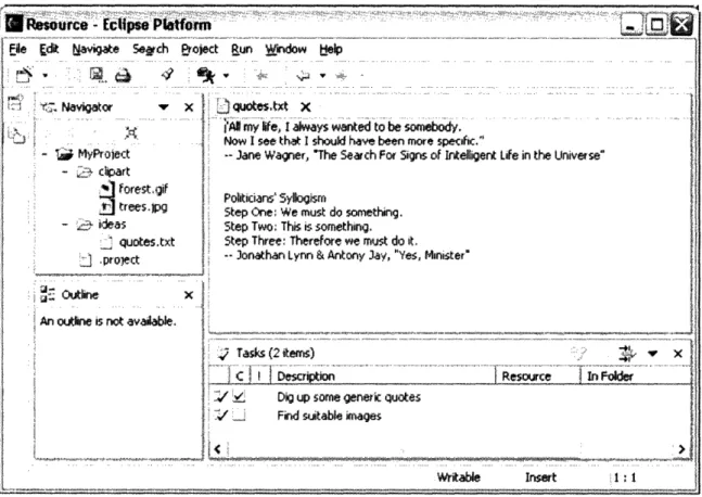
and a task list, as well as a menu bar and toolbar (see figure 4). What makes Eclipse special is that its entire architecture is designed with extensibility in mind. Plug-ins are
Figure 4: the default Eclipse IDE
the mechanism through which one can extend Eclipse's default IDE. A plug-in consists of Java code in a JAR library, some read-only files, and resources such as images [7]. Each plug-in also has a manifest file defining its relations to other plug-ins; in particular, the plug-in may declare in its manifest file some number of extension points, and some number of extensions to one or more extension points in other plug-ins. Because the platform's default IDE is itself a set of plug-ins, starting from those "build-in" plug-ins' extension points, one can supply a new plug-ins with extensions to the build-in plug-in's extension points, thereby extending the default IDE through its extension points. (A concrete example of such an extension may be to supply a new menu on the menu bar, or a new type of editor for certain types of files.) That same plug-in may also define its own extension points, so now another plug-in may then extend those extension points, and thereby extending the look and functionality provided by the first plug-in. As we can see, the plug-in mechanism allows the default Eclipse IDE to be extended indefinitely,
B
esurce - c~pse Phtorm a;Fle Ec t avigte Setch eroect Run Wndow bye
...
|~
Navigator ~ ...x IIL ~~~~~~... ~ ;...quotestct C~~ ~~ ~~~
~~~ ..+ ... ~~~~~~~~~~~~~~~~~~~~~~~~~~~~~~~~~ ...
. .
... .... ...
... ......gt
....,
...2,
.
... ... ... .- !: ..'' A rlife, I always y wantedtobesomebody.... .' . - AidNow I see that I sould have been more specific."
! My Project ]Jae Wagner, The Search For Signs of Intelligent Life in the Universe"
. cliart
.f orest,giffrtorest~gf Politicans'Sylogism
S trees.l Step One: We must do something. . - .: ideas Step Two; This is something.
quotes.txt Step Three: Therefore we must do it. ':~,pro~ect
j Xs? ;project 3onot~n Lynn & Atony 3ay, "Yes, tMinis er"
i~~~~
.S:; Outla W , .
An oline is not avaia.
Ta sk (2 items) :
i_ . ... ... ... .... . .
!: i~ !~ Dig up some genesi quotes ·' iw Find suitable images
Writable Irnsert 1: 1
If * * * - **CI~·- ·
![Figure 1: The structure of an intent specification, from [1].](https://thumb-eu.123doks.com/thumbv2/123doknet/14680374.559111/7.940.126.832.408.874/figure-structure-intent-specification.webp)
![Figure 2: sample SpecTRM-RL specification for an input element, from [6]](https://thumb-eu.123doks.com/thumbv2/123doknet/14680374.559111/12.940.139.737.176.908/figure-sample-spectrm-rl-specification-input-element.webp)