Design and Utility Assessment of Attitude Control
Systems for EVA Task Performance
by
Todd F. Sheerin
A.B., Harvard University (2012)
Submitted to the Department of Aeronautics and Astronautics
in partial fulfillment of the requirements for the degree of
Master of Science
at the
MASSACHUSETTS INSTITUTE OF TECHNOLOGY
September 2015
©2015 DLF Todd Fillmore Sheerin, All rights reserved.
The author hereby grants to MIT and The Charles Stark Draper
Laboratory, Inc. permission to reproduce and to distribute publicly
paper and electronic copies of this thesis document in whole or in any
part medium now known or hereafter created.
Author . . . .
Department of Aeronautics and Astronautics
August 20, 2015
Certified by . . . .
Jeffrey A. Hoffman
Professor of the Practice of Aeronautics and Astronautics
Thesis Supervisor
Certified by . . . .
Michele D. Carpenter
Technical Staff, Charles Stark Draper Laboratory
Thesis Supervisor
Accepted by . . . .
Paulo Lozano
Professor of Aeronautics and Astronautics
Chair, Graduate Program Committee
Design and Utility Assessment of Attitude Control Systems
for EVA Task Performance
by
Todd F. Sheerin
Submitted to the Department of Aeronautics and Astronautics on August 20, 2015, in partial fulfillment of the
requirements for the degree of Master of Science
Abstract
Low gravity astronaut extravehicular activity (EVA) missions using a maneuver-ing Jetpack and robotic servicmaneuver-ing and assembly missions could benefit from spacecraft systems capable of maintaining pointing stability during critical operations. The ad-dition of single-gimbal control moment gyroscopes (CMGs) to the attitude control system of these spacecraft could substantially improve the stability and pointing ac-curacy of the platform and could also conserve onboard fuel during missions. This thesis contains a description of recent work completed at Draper Laboratory and MIT’s Space Systems Laboratory (SSL) and Man Vehicle Laboratory (MVL) that explores the performance and utility of a combined control concept for a Jetpack sys-tem using thrusters and CMGs as actuators. Simulation of the Mobility Augmenting Jetpack with Integrated CMGs (MAJIC) at Draper is described as well as the design, integration and physical demonstration of a combined control system with the Syn-chronized Positoin Hold Engage Reorient Experimental Satellite (SPHERES) facility at the SSL. Primary contributions in simulation for the Jetpack application have fo-cused on implementing a new method for sizing CMG actuators and improving the performance and utility assessment strategies to compare a proposed MAJIC system with a Jetpack that does not include CMGs. Primary contributions with hardware within the context of the SPHERES facility have included the design, simulation, inte-gration and testing of a CMG peripheral actuator package and associated laboratory and reduced-gravity testing with NASA’s Flight Opportunity Program.
Thesis Supervisor: Jeffrey A. Hoffman
Title: Professor of the Practice of Aeronautics and Astronautics Thesis Supervisor: Michele D. Carpenter
Acknowledgments
I would like to acknowledge first the many advisors and mentors at both MIT and Draper that have have seen me transition from an undergraduate physics student to an engineer here at MIT. Most notable among them is Prof. Jeffrey Hoffman who has been an incredibly supportive and patient mentor and advisorsince the fall of 2010 when I first knocked on his door. I could not ask for a more enthusiastic and knowl-edgeable mentor. Bobby Cohanim and Phillip Cunio worked with me beginning also in 2010 and to this day continue to be helpful and constructive role-models, teachers and friends that I appreciate dearly. Among my advisors I must also acknowledge Prof. Kerri Cahoy for taking me under her wing and providing me with opportunities and support that I will never forget at the crucial transition between undergraduate and graduate programs. Michele Carpenter at Draper has provided reliable support and has proven to be a patient mentor throughout my graduate program; she has always been enthusiastic and engaged with my work and I owe her many thanks.
Draper Laboratory’s most generous support of this program must also be ac-knowledged: without their institutional support (Michele Carpenter, Bobby Cohanim, Kevin Duda) and their financial support (my Draper Laboratory Fellow status, the purchase of Honeybee Robotics CMG actuators and ProtoLabs CMG enclosures) this project would not have been possible. The kindness shown to me by Stacey Goulet at the Contracts Office, Carline Durocher at the Legal Department and Martha Porter and Brenan McCarragher at the Education Office have been most welcome when stress is at a maximum and time availability is at a minimum. In addition I owe my thanks and gratitude to Honeybee Robotics for providing Draper and MIT with control moment gyroscope actuators. They have proven to be a source of support throughout integration and testing and have made the physical realization of a com-bined control concept at Draper and MIT possible.
I’d also like to acknowledge Danilo Roascio for time and again proving his brilliance and willingness to help throughout the SPHERES integration effort, and Alvar Saenz-Otero for providing insight and direction to the project. I must also acknowledge
Mr. Paul Bauer, resident lab guru and most appreciated mentor without whom so many projects would never leave the drawing board. I also want to thank among my mentors Todd Billings and Dave Robertson in the AeroAstro Gelb machine shop for their insight and patience when helping me with my hardware projects over the years, I don’t think anyone has thanked them nearly enough for their tireless contributions to the research and education activities conducted at MIT.
In addition, I’d like to acknowledge the members of the 16.851 Fall 2013 course (Sam Schreiner, Tim Setterfield and Morris Vanegas) who spent so many hours working with me to realize a practical design for the implementation of CMGs on SPHERES, as well as the undergraduates that aided the program’s efforts as part of the 16.83X Fall 2013 and Spring 2014 courses. I must also thank the UROPs that helped me complete my research objectives over the past three semester, most notably Jose Gomez for his tireless work. Previous Draper student Celena Dopart provided me with human factors support during my research work that was much-needed; previous Draper student Jared Rize provided me with more insight concerning what might come of a team-based engineering process than I ever could’ve expected.
The MIT community and the Aero/Astro community in particular have also been pillars of support throughout my experience in this graduate program, and the friends that I’ve made across all departments constantly surprise and inspire me. Beth Marois and Marie Stuppard in the front office have always looked out for me and the other students like we were their own children and I can’t thank them enough. Lastly, the MIT community has provided me with one more gift: an incredibly supportive and loving girlfriend in Whitney. Without her support I may not have made it through this graduate school experience as the complete person I am today.
For my final acknowledgments, I want to thank those closest to me: my family and friends. Sometimes I feel like my parents, my sister, my grandparents, and my aunts, uncles, cousin and friends from home and from college feel the stress and pain of student life on my behalf more acutely than I do myself. My friends Zach, Penyen, Jordan, Juan and Shervin in particular have never stopped reminding me of why life is so precious. I wish to acknowledge the inspiration several family members have
given me: I have been inspired by my mother Nancy’s courage, my father Peter’s inquisitiveness, my sister Erica’s creativity, my grandmother Pearl’s togetherness, and my grandfather Merle’s imagination. They, along with my grandparents Dotty and Bob, have always been and always will be held close to my heart, providing me strength of will and character when all else fails.
Contents
1 Introduction 29
1.1 Motivation . . . 29
1.2 Thesis Focus . . . 31
1.3 MAJIC System Background . . . 35
1.3.1 Jetpack Heritage . . . 35
1.3.2 Previous Work on MAJIC . . . 36
1.4 MIT SPHERES Background1 . . . . 38
1.5 Dynamics and Attitude Control for a Jetpack and for SPHERES . . . 43
1.5.1 Reaction Control Overview . . . 45
1.5.2 Reaction Control with CMGs for Improved Stability . . . 48
1.6 Thesis Overview . . . 54
2 CMGs for a Jetpack: Concept, Design and Utility Analysis 57 2.1 MAJIC Concept . . . 58
2.1.1 MAJIC’s Concept Origins: NASA’s SAFER and Advanced Jetpack . . . 59
2.1.2 Control Configurations for MAJIC . . . 61
2.1.3 Mission Concepts . . . 64
2.2 Draper-MIT Simulation . . . 66
2.2.1 Thruster Model . . . 67
2.2.2 CMG Model . . . 69
1This section includes contributions by Tim Setterfield of the MIT SPHERES team, initially
2.2.3 6-DoF Suited Astronaut Dynamics Model . . . 71
2.2.4 Sensors and Data Logging . . . 72
2.2.5 Guidance and Navigation . . . 72
2.2.6 Control and CMG Steering with Desaturation . . . 73
2.2.7 EVA Mission Scenario Simulations . . . 75
2.3 MAJIC Design: CMG Actuator Sizing . . . 81
2.3.1 Maximum SWaP for a Practical MAJIC System . . . 81
2.3.2 CMG Actuator Sizing Method . . . 86
2.3.3 CMG Design Parameterization . . . 88
2.3.4 Largest CMG Specification . . . 93
2.3.5 Reducing CMG Size with a Monte Carlo Method . . . 93
2.3.6 Sizing Mission Selection and Sizing Results . . . 95
2.3.7 Monte Carlo Sizing Discussion . . . 97
2.4 MAJIC Utility Analysis . . . 99
2.4.1 Mission Scenario Performance and Mass-Cost . . . 101
2.4.2 Simple Task Performance and Mass-Cost . . . 112
2.4.3 Mass-to-Orbit Cost Projection . . . 126
3 CMGs for SPHERES: CDIO and Utility Analysis2 129 3.1 SPH-Halo-CMG Concept . . . 130
3.1.1 SPH-Halo-CMG System Requirements . . . 132
3.2 SPH-Halo-CMG Design . . . 134
3.2.1 CMG Sizing for SPHERES . . . 134
3.2.2 Structural Design . . . 137
3.2.3 Electrical Design . . . 142
3.2.4 Flight Software Design . . . 150
3.2.5 SPH-Halo-CMG Simulation . . . 156
3.3 SPH-Halo-CMG Integration . . . 165
2This chapter includes contributions by a team of graduate students including the author of
this thesis, Sam Schriener, Tim Setterfield and Morris Vanegas; these contributions satisfied partial requirements for the Fall 2013 16.851 MIT course on Space Systems Engineering, advised by Prof. Jeffrey A. Hoffman [1].
3.3.1 Hardware Integration . . . 166
3.3.2 Electrical Integration . . . 171
3.3.3 Software Integration . . . 173
3.4 SPH-Halo-CMG Operations . . . 174
3.5 SPH-Halo-CMG Utility Analysis for the SPHERES Simulation Results 176 3.5.1 Mission Duration Increase . . . 176
3.5.2 Preliminary Mass Trade Analysis . . . 177
4 Conclusion 181 4.1 MAJIC Research Conclusions . . . 181
4.2 SPHERES Research Conclusions . . . 184
4.3 Future Work . . . 185
4.3.1 Future MAJIC Work . . . 185
4.3.2 Future SPHERES Work . . . 187
List of Figures
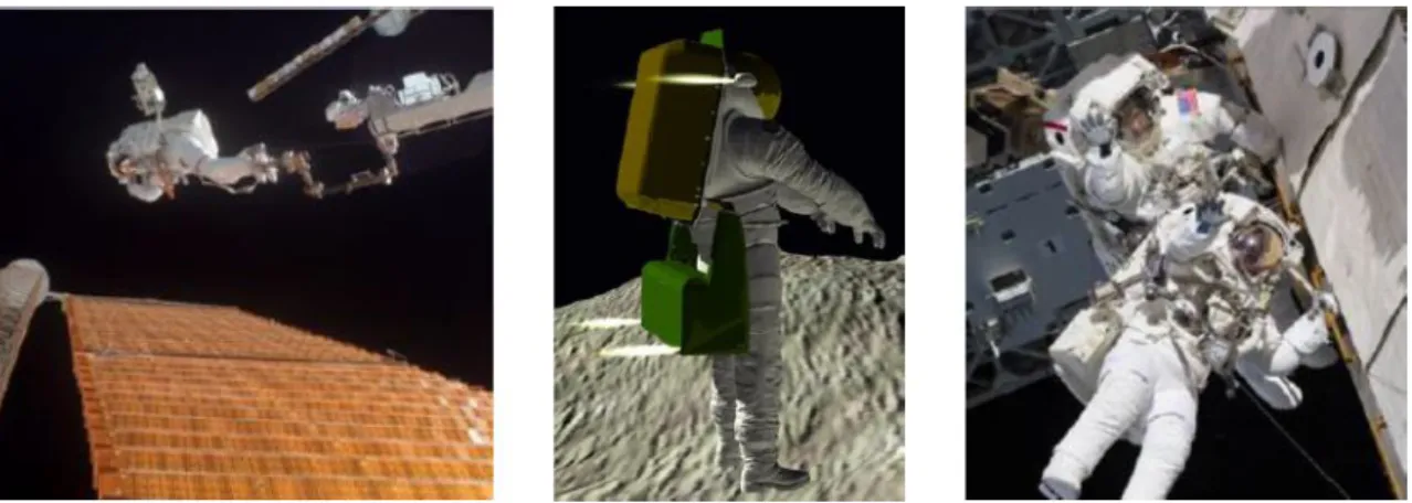
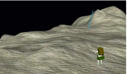
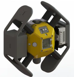
1-1 The Manned Maneuvering Unit and MAJIC. Left: US astronaut Bruce McCandless and the MMU, 1984; courtesy of NASA. Right: Suited astronaut concept with the Mobility Augmenting Jetpack with Integrated CMGs (MAJIC) system considered for this thesis following previous work at Draper and MIT [2, 3, 4]. . . 31 1-2 MAJIC at an asteroid. This screen-shot from a human simulation
trial of the MAJIC system conducted at NASA JSC in 2014 depicts the MAJIC system transporting an astronaut near the surface of an asteroid. [3] . . . 33 1-3 MIT’s INSPECT Spacecraft. The Integrated Navigation Sensor
Platform for EVA Control and Testing is one of many spacecraft vari-ants that the MIT SPHERES facility has been investigating; CMGs are integrated to improve pointing accuracy of the inspector system. . . . 34 1-4 The Astronaut Maneuvering Research Vehicle (AMRV). The
AMRV was flown inside the volume of the Skylab orbiting facility as part of the M509 Experiment on the Skylab 3 Mission, 1973 [5]. The AMRV featured 6 CMGs in three scissor-pair configurations for attitude control testing. Image courtesy of NASA. . . 36 1-5 SPHERES on the ISS. Astronaut Scott Kelly poses for a photograph
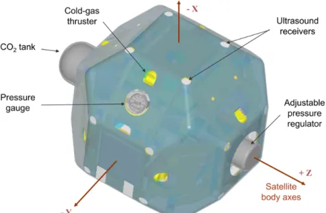
with three MIT SPHERES Satellites aboard the International Space Station. . . 39 1-6 A SPHERES satellite. SPHERES-frame body axes are shown as
1-7 SPHERES and the Halo Expansion.Up to six peripherals can be interfaced with Halo and communicate with the central SPHERES satellite. . . 41 1-8 Two SPHERES Docked.The proposed docked configuration for flight
aboard NASA’s Reduced Gravity Aircraft in August 2015; the Sec-ondary SPHERES satellite will execute open-loop thruster firings to in-duced known disturbance torques that the Primary SPHERES satellite will reject either with thruster-only attitude control or CMG attitude control. Closed-loop slew maneuvers will also be completed using this docked configuration as well as with an undocked Primary SPHERES satellite. . . 42 1-9 Phase plane controller for attitude control with thrusters.
Al-lowable bounds for errors in attitude, θerr, and angular rate, ωerr, are
selected and thruster firings only occur should the deadband defined by these bounds is exceeded. For a controller with proportional gain Kθ
and differential gain Kω, no controller output is commanded along the
dotted line. . . 46 1-10 Vectors and scalars for a single-gimbal CMG. Definition
1-11 CMG pyramid configuration and angular momentum enve-lope depicting singular surfaces. Left: A 4-CMG pyramid config-uration, pyramid angle β = 54.74◦; image modified from [7]. The ith
CMG has angular momentum hcmg,i and a gimbal axis ˆgi. Shaded blue
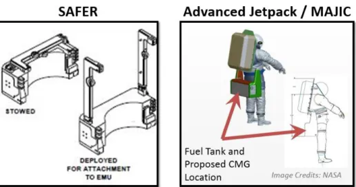
circles on each triangular face indicate available positions for individual CMG angular momentum vectors. Right: The pyramid array’s nearly spherically symmetric momentum envelope with singular surfaces pic-tured; image modified from [8]. When the CMG array’s momentum reaches the edge of this envelope when CMG rotors are gimbaled such that CMG angular momenta add constructively to a maximum degree, saturation occurs. An external torque provided by thrusters is required to return the CMG array to a fully controllable state. . . 53 2-1 NASA’s SAFER and the Advanced Jetpack / MAJIC
Con-cept. Left: Diagram for the Simplified Aid for EVA Rescue emergency-only astronaut mobility unit currently in use at the ISS for astronaut EVAs. Right: The NASA JSC Advanced Jetpack concept; arrows indi-cate the location of fuel tanks; for the MAJIC system, half of the fuel tanks would be replaced by the CMG subsystem with minimal impact to Jetpack size and weight. . . 58 2-2 A 4-CMG pyramid array configuration. This array has a pyramid
angle β = 54.74◦. The ith CMG has angular momentum h
i and a
gimbal axis ˆgi. Shaded blue circles on each triangular face indicate
available positions for angular momentum vectors hi. Image modified
from [7]. . . 62 2-3 Control Loop Diagram for MAJIC ACS. In the simplest
im-plementation, all torques are controlled by CMGs and all forces are controlled by thrusters. . . 64
2-4 Three mission concepts for the CMG-augmented Jetpack. Left: A NASA photograph of an ISS solar array inspection EVA - with a Jetpack, inspection activities would not be limited by the reach of the ISS robotic arm. Middle: A sample recovery mission to near-Earth objects (NEOs) like asteroids and comets would benefit from Jetpack mobility and CMG stability. Right: In the event of an emergency dur-ing any low gravity EVA mission, a CMG-augmented Jetpack would enable reliable crew member rescue with stable pointing during transit with a large external mass. . . 65 2-5 The Draper-MIT Simulink Diagram. A top-level diagram
depict-ing the principle modules of the MATLAB-Simulink simulation used to design and evaluate the utility of MAJIC. . . 67 2-6 Trajectory profile for the solar array inspection mission. The
inspection of one pair of solar arrays at the International Space Station is simulated; the coordinates used in the plot are fixed in the ISS frame. 75 2-7 Asteroid Sampling Mission I: Survey. Flight trajectory for the
asteroid sampling mission I. Axes labeled in the ACI frame. An initial approach to the asteroid is followed by a plane change and continued approach for detailed surveying of the asteroid’s surface. . . 76 2-8 Asteroid Sampling Mission II: Sampling Actions. Flight
trajec-tory for the asteroid sampling mission II. A linear translation of 50 meters in the x-axis (ACI) lasting 220 seconds is followed by simulated sampling activities at the asteroid’s surface for another 272 seconds. Sampling activities include an overhead reach, hammer blow, and reach to the hip in that order. . . 77
2-9 Asteroid Mission II Linear Trajectory and Astronaut Torques. (a) Linear trajectory in the x-axis of the asteroid-centered inertial frame. (b) Astronaut torque magnitudes, with a reminder for the MAJIC-body coordinate frame referenced for torque magnitudes; the time scale here is the same as in (a), showing the entire length 492 seconds of the mis-sion. (c) A zoomed perspective of the astronaut torque profiles, as well as labels indicating the individual overhead reach, hammer blow and hip reach actions. . . 78 2-10 Trajectory profile for the crew member rescue mission. An
astronaut departs from the airlock to rescue a fellow crew member; a picture courtesy of NASA is used to visualize the hypothetical mission. 79 2-11 Jetpack Concept Dimensions with CMG Location Options.
Regions 1, 2, and 3 illustrate three options for CMG subsystem place-ment in a MAJIC system based on the JSC Jetpack design. . . 82 2-12 ISS Solar Array Inspection Mission Performance (a) Full
at-titude error profile for CMG+Thr combined control (green), the tight deadband thruster-only (red) and loose deadband thruster-only (blue); (b) Attitude error for a 50 degree slew maneuver at mission start. The slightly more negative slope of the tight deadband (red) profile results in an overall lower RMS attitude error for tight deadband thrusters, though CMGs ultimately reach the commanded attitude first; (c) A zoomed-in perspective of the attitude error profile over the whole mis-sion, showing the CMG’s superior performance for mission time 49s+. 103 2-13 Asteroid Sampling Mission I Performance (a)Attitude error
profile for the newly-sized CMGs (green), the thruster-only 0.5 dead-band ACS (full width, corresponding to ± 0.25 degrees) (red) and the thruster-only 2.0 deadband (full width, corresponding to ± 1.0 degrees) (blue); (b) A zoomed-in perspective of the attitude error profile, show-ing the CMG’s superior performance for a majority of the mission; (c) Fuel consumption profile (color scheme same as in attitude error plots). 105
2-14 Asteroid Sampling Mission II Performance A translation of 85 meters is simulated beginning at mission time 0 s and ending at mission time 245 s; following this, a set of sampling maneuvers between mission time 300 s and 355 s is simulated as disturbance torques on the MAJIC system. (a) The translation profile in time for this mission segment; (b) The disturbance torque profile induced on the MAJIC system as a function of time; (c) Attitude error profile for the combined CMG-thruster MAJIC system (green), the CMG-thruster-only 0.5 deadband ACS (full width, corresponding to ± 0.25 degrees) (red) and the thruster-only 2.0 deadband (full width, corresponding to ± 1.0 degrees) (blue). . . . 107 2-15 Asteroid Sampling Mission II Mass-Cost A translation of 85
me-ters is simulated beginning at mission time 0 s and ending at mission time 245 s; following this, a set of sampling maneuvers between mission time 300 s and 355 s is simulated as disturbance torques on the MAJIC system. (a) The translation profile in time for this mission segment; (b) The disturbance torque profile induced on the MAJIC system as a function of time; (c) Fuel consumption profile for the combined CMG-thruster MAJIC system (green), the CMG-thruster-only 0.5 deadband ACS (red) and the thruster-only 2.0 deadband (blue). . . 109 2-16 Crew Member Rescue Mission Performance (a) Trajectory
pro-file; (0,0,0) is taken to be the incapacitated crew member’s location in the ISS inertial frame; (b) Attitude error profile for CMGs (green), the thruster-only 0.5 degree deadband ACS (full width, corresponding to ± 0.25 degrees) (red) and the thruster-only 2.0 degree deadband (full width, corresponding to ± 1.0 degrees) (blue); (c) Attitude errors for the last 600 seconds of the mission, showing the CMG’s superior per-formance for the critical mass-offset return phase of the mission. . . . 111
2-17 Crew Member Rescue Mission Fuel Consumption. Fuel mass consumed over the course of the simulated crew member rescue mis-sion is depicted for the tight deadband thrusters (red), loose deadband thrusters (blue) and the combined control Thr+CMGs (green). Note the smaller rate of fuel consumption for the combined control imple-mentation for the majority of the mission as well as the increased fuel consumption for the same implementation during de-saturation proce-dures. . . 113 2-18 Attitude error and fuel consumption profiles for a 10 meter
translation. Solid lines correspond to translation results with no mass offset and dotted lines correspond to results for translation with mass offset corresponding to the transport of an incapacitated crew member in a rescue scenario; distance traveled is indicated at the top of the figure.115 2-19 Hammer Blow (strong- 10 Nm scale) Disturbance Torque
Pro-file and Performance. (a) Disturbance torque profile in the MA-JIC body reference frame (x, y, z torques represented in magenta, red and blue respectively); (b) Absolute attitude error (CMGs in green, thrusters with 0.5 degree deadband in red, thrusters with 2.0 degree deadband in blue); (c) Fuel consumption (color scheme same as in at-titude error plot). . . 120 2-20 Hammer Blow (weak- 2 Nm scale) Disturbance Torque Profile
and Performance. (a) Disturbance torque profile in the MAJIC body reference frame (x, y, z torques represented in magenta, red and blue respectively); (b) Absolute attitude error (CMGs in green, thrusters with 0.5 degree deadband in red, thrusters with 2.0 degree deadband in blue); (c) Fuel consumption (color scheme same as in attitude error plot). . . 121
2-21 Hip Reach Disturbance Torque Profile and Performance. (a) Disturbance torque profile in the MAJIC body reference frame (x, y, z torques represented in magenta, red and blue respectively); (b) Absolute attitude error (CMGs in green, thrusters with 0.5 degree full width deadband in red, thrusters with 2.0 degree full width deadband in blue); (c) Fuel consumption (color scheme same as in attitude error plot). . 123 2-22 Overhead Reach Up Disturbance Torque Profile and
Perfor-mance. (a) Disturbance torque profile in the MAJIC body reference frame (x, y, z torques represented in magenta, red and blue respec-tively); (b) Absolute attitude error (CMGs in green, thrusters with 0.5 degree full width deadband in red, thrusters with 2.0 degree full width deadband in blue); (c) Fuel consumption (color scheme same as in at-titude error plot). . . 124 2-23 Mass-to-Orbit Projections for a Jetpack with and without
CMGs. Combined control with MAJIC requires thruster fuel, a CMG actuator suite and associated extra battery mass dedicated to CMGs to be sent to orbit; simple thruster-only control with a Jetpack only requires thruster fuel, but with more aggressive cargo delivery given the poorer fuel economy of a thruster-only system. . . 127 3-1 SPH-Halo-CMG Flight Configurations The SPH-Halo-CMG
con-figuration is used to host two different concon-figurations used for flight test-ing aboard NASA’s Reduced Gravity Aircraft. The INSPECT configu-ration has an optical range-finder (ORF), stereoscopic cameras (Optics Mount), and a thermographic camera (ThermoCam); the Docked con-figuration has a Universal Docking Port used to dock to a Secondary SPHERES satellite. . . 130
3-2 CMG pyramid configuration and angular momentum enve-lope depicting singular surfaces. Left: A 4-CMG pyramid config-uration, pyramid angle β = 54.74◦; a Box-90 configuration is equiva-lent to a pyramid configuration with a pyramid angle β = 90◦. Right: The pyramid array’s nearly spherically symmetric momentum envelope has dimensions 3.15 hrotor× 3.15 hrotor× 3.26 hrotor (pictured); by
comparison, a Box-90 momentum envelope has dimensions 4 hrotor×
4 hrotor× 2 hrotor; images modified from [7] and [8] . . . 137
3-3 Mechanical design for SPH-Halo-CMG. (a) and (b) The CMGs attached to Halo in the Box-90 configuration. (c) The CMGs attached to Halo in the pyramid configuration. (d) An exploded view of the top CMG assembly. (e) An exploded view of the bottom CMG assembly. Image credit: Tim Setterfield [1]. . . 139 3-4 SPHERES keep-out zones. Relevant keep-out zones for the Halo
expansion are shown with the CMG system in its Box-90 configuration. (a) Right view of thruster keepout zones. (b) Bottom view of thruster keepout zones. (c) Right view of ultrasonic keepout zones. (d) Bottom view of ultrasonic keepout zones. . . 141 3-5 A top view of two SPHERES satellites with Halo and on
air carriages, attached 0.1 m apart. Two thrusters exert on the active SPHERE a force Ft, creating both an acceleration and an adverse
moment τ . Image adapted from [1] . . . 142 3-6 Electrical interface schematic for SPH-Halo-CMG system. The
path of information and power from SPHERES to CMGs is depicted. Image credit: Morris Vanegas, [1]. . . 144 3-7 SPHERES expansion port schematic. Expansion port aluminum
plate dimensions and the 50-pin connector used to interface to the SPHERES satellite. . . 145 3-8 Pin layout for the expansion port. SPHERES expansion port
3-9 VERTIGO expansion port. Expansion side of the VERTIGO avion-ics stack showing four threaded holes for captive thumbscrews and a 50-pin connector. . . 147 3-10 VERTIGO expansion port electrical interface pin assignments. 148 3-11 Halo expansion mechanical interface. Diagram of one of two
halves of the Halo expansion; each half hosts three total expansion ports to interface external payloads or actuators to the central SPHERES satellite. . . 149 3-12 USB to serial adapter pin assignments. . . 149 3-13 SPHERES control loop. A simplified depiction of the control loop
on the SPHERES satellite including only key elements. Additionally, the type of data exchanged between each block is shown. The blocks in grey are implemented in the controller software, while the green blocks are hardware components that had to be simulated. Image credit: Sam Schreiner [1]. . . 150 3-14 SPHERES control loop with CMGs The conceptual illustration
of the control loop on the SPHERES satellite, extended to command and interface with the CMG payload. This high-level design was used to guide the more detailed software design process. The blocks in grey are implemented in the controller software, while the green blocks are hardware components that had to be simulated. Image credit: Sam Schreiner, [1]. . . 153 3-15 Multithreaded scheduling for SPHERES control The action of a
5 Hz control thread (represented by a solid blue line) is traced; it first ac-cesses data from the metrology thread, then commands the CMG thread (running on the CMG control board). On every fifth control cycle, the main 5 Hz control thread commands thrusters after first commanding the infrared/ultrasound (IR/US) thread to cease global metrology (used to locate the SPHERES within the experiment volume) in preparation for thruster actuation, which would interfere with US sensor operation. 154
3-16 Scissor pair diagram A scissor pair CMG configuration generates torque τscissor about a single axis by constraining gimbal angles φ of the
pair to be equal and opposite at all times, usually by mechanical means. Image modified from [9] . . . 159 3-17 Docked SPHERES configuration The active SPHERES satellite
is to the left; when a translation burn is executed, a reaction torque is executed on the system since the system center of mass (CM) is off-set from the active SPHERES’ thruster envelope. Force vectors corresponding to the active SPHERES’ thruster locations are labeled to highlight this phenomenon. Image adapted from [1]. . . 161 3-18 Performance plots for Docked simulation. Top Left: Linear
po-sition (m); Top Right: Attitude error (rad); Mid Left: Linear velocity (m/s); Mid Right: Angular velocity (rad/s); Bottom Left: Fuel con-sumed (g); Bottom Right: Scissor pair gimbal angle (rad). Graphs from 16.851 final report [1]. . . 163 3-19 Astronaut EVA maneuver with SPHERES A series of
screen-shots depicting a maneuver designed to imitate an astronaut conducting EVA maintenance activity at two different locations. This animation is quantitatively assessed in Figure 3-20. Images from 16.851 final report [1]. . . 164 3-20 Quantitative results for EVA astronaut manuever with SPHERES
From left to right, top to bottom: Plots of the linear position, angular position, linear velocity, angular velocity, propellant usage, and scis-sor pair gimbal angle (or CMG Usage) for the combined control system (blue dashed line) and the thrusters-only system (red solid line).Graphs from 16.851 final report [1]. . . 165 3-21 Initial and updated designs for CMG enclosures and
electron-ics housing. Left: The initial CAD model from Fall 2013 [1]; Right: The final, manufactured version. . . 167
3-22 Final damping solution for CMGs. A double-damping solution was arrived at as the preferred option for reducing vibrations induced on the Halo structure from improperly balanced CMGs. Ring-dampers were used to interface the control electronics box (and Halo) with a base plate; a set of sandwich-style dampers then separate the CMG enclosures from the base plate. . . 168 3-23 Vibration profile for undamped and damped mechanical
as-semblies, worst case vibrations. Left: Accelerometer readings for the undamped, worst-case CMG-120. Right: Accelerometer readings for the same CMG-120 actuator stood-off with the damping solution depicted in Figure 3-22. . . 169 3-24 Schematic of the Halo-to-CMG printed circuit board. Major
components have been labeled. . . 172 3-25 Block diagram of software implementation. SPHERES manages
a control algorithm that determines requested forces and torques; forces are passed to thrusters (not shown) and torques are passed to VER-TIGO, which converts the SPHERES torque command to a command the CMG electronics can interpret. Telemetry data from CMGs is stored on VERTIGO for post-processing, while key information such as flywheel rates, gimbal angles and gimbal rates are passed to SPHERES for display on the controller’s laptop GUI. . . 174 3-26 The INSPECT configuration at the end of the undergraduate
course 16.831 in the spring of 2014. Inspection operations on the MIT SSL’s flatfloor facility were demonstrated with this partially-integrated INSPECT system; at the time of this photograph, CMGs are being commanded not by SPHERES but by an external laptop. . . 175
3-27 Propellant consumption for the SPHERES-simulated astro-naut EVA maneuver. The propellant used to conduct a simulated astronaut EVA maneuver using the SPHERES satellite with thrusters as the only actuator (red solid line) and with the combined thruster and CMG actuators (blue dashed line). This comparison clearly out-lines the fuel saved by using CMGs to augment thruster actuation. The green vertical lines indicate the beginning and ending of maneuvers cor-responding to Figure 3-19. . . 178
List of Tables
2.1 CMG SWaP Constraints . . . 83 2.2 Saft VES Battery Models Applicable to MAJIC . . . 85 2.3 CMG Inertia Bounds for Sizing . . . 89 2.4 Angular momentum bounds for SWaP-compatible MAJIC
CMGs A flywheel rate of 30 krpm is assumed as well as inertia bounds listed in Table 2.3 to arrive at the bounds listed here. . . 90 2.5 Gimbal Rate Bounds to Achieve 2 Nm Torques . . . 91 2.6 Maximum torques achievable by SWaP-compatible CMGs . . 91 2.7 CMG Parameter Bounds for Sizing . . . 92 2.8 Specifications for the largest-SWaP MAJIC CMG design . . 93 2.9 Monte Carlo Sizing Performance Metrics . . . 94 2.10 Simulated mission details Mission time, ∆V , RMS attitude errors
for a thruster-only (2 degree deadband) Jetpack are listed for each sim-ulated mission . . . 96 2.11 Specifications for MAJIC CMG designs . . . 98 2.12 Specifications for the MAJIC CMG design evaluated for utility100 2.13 Mission Scenario Performance Results . . . 101 2.14 10m Translation Performance . . . 117 2.15 10m Translation Mass Cost . . . 118 2.16 Astronaut Motions Simulated. Peak torques are listed and are
measured in the MAJIC body coordinate frame acting on the MAJIC system’s center of mass. . . 119 2.17 Human Action Mass Cost . . . 125
3.1 Top-Level System Requirements. Table includes requirement state-ments, implications on project goals for each requirement, and the ver-ification method necessary for each requirement. . . 133 3.2 Angular momentum and torque specifications for the
Honey-bee Robotics CMG-120 actuator. Nominal values correspond to a flywheel rate of 6 krpm while the peak values correspond to a flywheel rate of 8 krpm. . . 135 3.3 SPH-Halo-CMG System Properties with CMG-120 Actuators
An outline of the scaling analysis. Performance of the CMG-120 in pyramid and Box-90 configurations are considered. * The maximum pyramid configuration torque is equal to (4 τcmg × sin(β)) where β =
54.74◦ is the skew angle; † The maximum Box-90 configuration torque is not symmetric; maximums along principal axes (2h0 and 4h0) and
at 45◦ (2√2h0) are shown. . . 136
3.4 Mass budget for SPH-Halo-CMG system. The masses of all ma-jor components excluding the electronic components on the connector PCB and the wires connecting the control board to the CMGs. . . 140 3.5 Details of the SPH-Halo-CMG + SPH scenario (Figure 3-5)
Table includes expected performance of both the pyramid and Box-90 CMG arrays using the Honeybee Robotics CMG-120. Analysis credit: Tim Setterfield [1]. . . 143 3.6 Control Frequencies. Initial design values are used in preliminary
simulations while the attitude-only design is implemented for the Au-gust 2015 Reduced Gravity Re-Flight Opportunity. Values correspond to CMG attitude control; for thruster-only attitude control, thrusters would fire at the frequency listed for CMG Command. . . 156 3.7 Mass trade-off for simulated SPH-Halo-CMG system A
sum-mary of the mass trade-offs involved in adding a CMG payload to the SPHERES satellite testbed. These trade-offs are maneuver-dependent, and are thus presented for both the ‘EVA’ and ‘Docked’ maneuvers. . 180
List of Acronyms
ACI - asteroid-centered inertial (frame) ACS - attitude control system
CAD - Computer-Aided Design CEV - Crew Exploration Vehicle CMG - control moment gyroscope CM - center of mass
DCM - direction cosine matrix DoF - degree-of-freedom
EMU - Extravehicular Mobility Unit EPS - electrical power system EVA - extravehicular activity
GNC - guidance, navigation and control GUI - graphical user interface
INSPECT - Integrated Navigation Sensor Platform for EVA Control and Testing IR - infrared
ISS - International Space Station JSC - Lyndon B. Johnson Space Center LEO - low-Earth orbit
LVLH - local vertical local horizontal frame MVL - MIT Man Vehicle Laboratory
MIT - Massachusetts Institute of Technology MMU - Manned Maneuvering Unit
NASA - National Aeronautics and Space Administration NEA - near-Earth asteroid
NEO - near-Earth object
ORU - Orbital Replacement Unit PCB - printed circuit board PD - proportional-derivative
PID - proportional-integral-derivative RGA - reduced gravity aircraft RMS - root mean square
SAFER - Simplified Aid for EVA Rescue
SPHERES - Synchronized Position Hold Engage and Reorient Experimental Satellites SPH-Halo-CMG - A SPHERES configuration including the Halo expansion and CMGs SSL - MIT Space Systems Laboratory
UDP - SPHERES Universal Docking Port
UROP - MIT Undergraduate Research Opportunity Program US - ultrasound
USB - Universal Serial Bus
Chapter 1
Introduction
A broad range of human space exploration missions could benefit from an astro-naut mobility unit capable of providing six-degree-of-freedom (6-DoF) control during extravehicular activities (EVA). At the moment, NASA’s plans for long-term human exploration are uncertain, but several facts have become clear: on-going development of the Space Launch System (SLS) heavy-lift launch vehicle and the Orion Crew Ex-ploration Vehicle (CEV) promise a near-future capability to transport astronauts to destinations like the moon, low gravity objects like asteroids, and ultimately Mars.
1.1
Motivation
The need to develop an operational Jetpack among other technologies has been identified in NASA’s Human Exploration Destination Systems Roadmap [10] and is motivated not by a particular mission architecture or proposed mission but instead by the long-term goals of NASA’s human exploration program. NASA is currently conducting research for an Advanced Jetpack at the Johnson Space Center (JSC) that might fill this technology gap, though the need for off-surface EVA mobility will become more pronounced when operations with the Orion CEV begin1. The reason is that unlike the previously-proposed Multi-Mission Space Exploration Vehicle
1The term “Advanced Jetpack” is the current name for NASA’s next back-mounted thruster
(MMSEV), a pressurized crew vehicle designed for low gravity exploration of near-Earth objects (NEO) and near-near-Earth asteroids (NEA), the Orion CEV design does not include plans for a robotic arm. This implies that EVAs around the Orion CEV are to be restricted to the mobility afforded by the few hand-holds on the vehicle’s external surface. This restriction would limit the potential value that could be gained from EVAs conducted in the vicinity of the CEV, especially when visiting low gravity bodies of scientific interest.
While an Advanced Jetpack promises to enhance the utility of deep space human exploration missions when the Orion CEV enters operation in the near future, benefits of an Advanced Jetpack could be realized now at the International Space Station (ISS). A picture of the Manned Maneuvering Unit (MMU), NASA’s previous back-mounted thruster mobility unit, as well as the Advanced Jetpack variant described further in this thesis are shown in Figure 1-1. The ISS solar arrays are bombarded by radiation and micrometeorites that degrade the arrays’ performance over time. Periodically, EVAs are conducted in which astronauts use the ISS robotic arm to visually inspect the arrays, but the robotic arm does not extend far enough to allow for complete inspection. An Advanced Jetpack would enable a full inspection of the ISS solar arrays. The expanded mobility afforded by a Jetpack would also enable more complex maintenance scenarios than are currently possible for consideration in EVA missions, including installation of Orbital Replacement Units (ORU). In addition, more direct travel routes and reduced tethering requirements for routine EVAs at the ISS would reduce crew fatigue and improve efficiency of EVA operations. The simplification of EVA translation paths has the added benefit of potentially saving mass and cost needed to support EVA operations. Finally, an Advanced Jetpack would enable astronauts to conduct emergency rescue operations for crew members that have become untethered or otherwise incapacitated beyond the reach of a robotic arm, much like the Shuttle was able to maneuver to rescue endangered crew members in pre-ISS missions.
With potential mission applications that include ISS solar array and ORU inspec-tion and maintenance, as well as crew member rescue and in the future Near-Earth
Figure 1-1: The Manned Maneuvering Unit and MAJIC. Left: US astronaut Bruce McCandless and the MMU, 1984; courtesy of NASA. Right: Suited astronaut concept with the Mobility Augmenting Jetpack with Integrated CMGs (MAJIC) system considered for this thesis following previous work at Draper and MIT [2, 3, 4].
Object (NEO) exploration and sample recovery, the Jetpack will be required to pro-vide 6-DoF control to astronauts or robotic configurations conducting a broad range of tasks, often without the aid of hand-holds. This means that an equally broad range of reaction torques are expected to be induced on the Jetpack system that must be counteracted to maintain platform stability throughout any given mission. The sta-bility of the platform becomes especially important for precise EVA tasks including sample recovery activities at a low gravity astronomical body and experimental pay-load installation and maintenance.
1.2
Thesis Focus
This thesis describes the design exploration of introducing CMGs in the attitude control system (ACS) of the Jetpack as well as in the SPHERES facility. Primary contributions described fall into two broad categories:
1. First, a Draper-MIT simulation of the Jetpack system in a MATLAB-Simulink environment corresponding to various system configurations operating in the
vicinity of the ISS or a low-gravity Near-Earth Asteroid (NEA); and
2. Second, a hardware demonstration of combined thruster and CMG control of the Synchronized Position Hold, Engage, Re-Orient Experimental Satellite (SPHERES) facility at the MIT Space Systems Laboratory (SSL).
The Draper-MIT Jetpack simulation provides the capability to explore the design for CMG actuators to include in the MAJIC system for specific mission profiles and to evaluate the performance of combined CMG-thruster and thruster-only implemen-tations for a broad range of missions. Figure 1-2 depicts a graphical representation of an astronaut using MAJIC to operate near an asteroid’s surface. The addition of small control moment gyroscopes (CMGs) to the Jetpack could improve the at-titude stability of the EVA platform beyond what is possible with an all-thrusters attitude control system (ACS). In addition to the extra stability, CMGs might also conserve on-board fuel and extend the length of EVA missions since thrusters would only be used for translation and CMG desaturation when necessary. Preliminary studies conducted by the Charles Stark Draper Laboratory (Draper) and the Mas-sachusetts Institute of Technology (MIT) for a Mobility-Augmenting Jetpack with Integrated CMGs (MAJIC) system provides an indication that such a system might provide stability and fuel economy benefits for a new Jetpack system [2]. A notional representation of the MAJIC system is depicted to the right of the MMU in Figure 1-1.
The MAJIC system is conceived to be a human-piloted EVA spacecraft, but it shares several key characteristics with autonomous vehicles proposed for on-orbit assembly, robotic servicing of satellites, reconfigurable robotic inspection and main-tenance EVA spacecraft outside the ISS and astronaut assistant spacecraft inside the ISS. First, all of these spacecraft must operate in the vicinity of highly valued as-sets; second, all these spacecraft must conduct precision tasks; and finally, all of these spacecraft must control the orientation and position of variable-size and variable-mass systems to accomplish their objectives.
Figure 1-2: MAJIC at an asteroid. This screen-shot from a human simulation trial of the MAJIC system conducted at NASA JSC in 2014 depicts the MAJIC system transporting an astronaut near the surface of an asteroid. [3]
The hardware demonstration effort involving SPHERES enables the capability to immediately compare performance of the two types of systems (i.e. thruster ACS vs. CMG ACS) on a physical satellite system representative of the MAJIC system or small robotic systems such as autonomous robotic service and assembly or robotic EVA inspection and maintenance that would similarly benefit from precise pointing and high torque capabilities.The fact that the SPHERES satellites already have the capacity to be programmed for control modes such as attitude hold only strengthens the parallelism between SPHERES and MAJIC.
The SPHERES facility is composed of three satellites on orbit inside the ISS and several matching satellites in MIT’s Space Systems Laboratory (SSL) and NASA Ames Research Center. SPHERES acts as a reconfigurable controls research program with over 15 years of development history and with nearly 10 years experience aboard the ISS as a microgravity experimental testbed. In the past few years, the SPHERES facility has seen the introduction of Halo, an expansion port enabling up to six pay-loads to interface with a central SPHERES satellite, and the universal docking port (UDP) enabling multiple SPHERES to remotely sense and dock to one another. To-gether, these new technologies allow the SPHERES facility to be used to investigate research topics in autonomous on-orbit assembly, robotic servicing of satellites, recon-figurable robotic inspection and maintenance EVA spacecraft and astronaut assistant
Figure 1-3: MIT’s INSPECT Spacecraft. The Integrated Navigation Sensor Plat-form for EVA Control and Testing is one of many spacecraft variants that the MIT SPHERES facility has been investigating; CMGs are integrated to improve pointing accuracy of the inspector system.
spacecraft. That is, the latest state of the SPHERES facility provides a mature plat-form to evaluate the utility of adding CMGs for enhanced attitude control. Figure 1-3 depicts a computer-aided design model for a prototype reconfigurable inspection spacecraft with integrated CMGs named the Integrated Navigation Sensor Platform for EVA Control and Testing (INSPECT) built at MIT’s Space Systems Laboratory as part of this thesis and the MIT senior undergraduate space systems design course 16.83.
What follows is a description of the background for both Jetpack and SPHERES satellite technologies as well as the previous work completed that serves as a foun-dation for the work presented in this thesis. Next, introductory concepts of attitude control with and without CMGs is presented. Finally, this introductory chapter con-cludes with an overview of the thesis contained herein.
1.3
MAJIC System Background
1.3.1
Jetpack Heritage
Astronaut mobility units have several notable historical precedents that have been tested and operated in low-Earth orbit (LEO) over the years. Following the Apollo program, NASA developed the MMU pictured on the left in Figure 1-1, a back-mounted thruster mobility unit designed to enable astronauts to aid with satellite capture operations [11]. The MMU successfully met its operational goals on a handful of missions in the early 1980s. On STS-51A, for instance, astronauts Joseph Allen and Dale Gardner retrieved malfunctioning satellites Palapa-B2 and Westar-VI with the aid of the MMU [12]. After the Challenger disaster in 1986, though, the decision was made to retire the MMU. Apart from cost considerations, the decision was motivated by a lesson learned from a failed attempt at grappling the Solar Maximum Mission spacecraft with the MMU on STS-41C in 1984: during this mission it was found that the use of a robotic arm alone was a safe and effective alternative for satellite capture [13]. It wasn’t until 1994 that another 6-DoF capable mobility unit, the Simplified Aid for EVA Rescue (SAFER), was tested on-orbit during the STS-64 mission. Unlike the MMU, SAFER was never intended to be used during nominal operations but is instead an emergency-only option for astronauts to self-rescue in the event of tether separation [14]. The SAFER has since become a trusted default contingency for maintaining crew safety during EVAs, especially during the construction of the International Space Station (ISS).
Interestingly enough, the concept of using CMGs in an astronaut mobility unit to achieve performance gains over a thruster-only system is not entirely new. In the initial design studies for the MMU, a unit that included CMGs was built and flown inside the Skylab orbiting facility as part of the M509 Experiment in 1973 pictured in Figure 1-4 [5]. Despite the greater stability afforded by CMGs, the final MMU design did not include CMGs and instead relied only on thrusters for both position and attitude control. The decision to exclude CMGs from the MMU’s design was driven by the fact that the target satellite capture system design for the MMU did
Figure 1-4: The Astronaut Maneuvering Research Vehicle (AMRV). The AMRV was flown inside the volume of the Skylab orbiting facility as part of the M509 Experiment on the Skylab 3 Mission, 1973 [5]. The AMRV featured 6 CMGs in three scissor-pair configurations for attitude control testing. Image courtesy of NASA.
not require a high degree of astronaut movement precision or platform stiffness, and because CMG options at the time were too large and required too much power to justify for the MMU given the system’s objectives. The miniaturization of CMGs in recent years as well as the evolving human exploration goals of the near future together motivate a serious reconsideration of the combined control of a Jetpack with thrusters and CMGs, a topic which features prominently in this thesis.
1.3.2
Previous Work on MAJIC
Previous MAJIC system design and operator evaluation studies at Draper and MIT have focused on developing a simulation environment and performing Monte Carlo CMG actuator sizing and operator evaluation studies. Following the initial system concept study documented in [2], a detailed model-based simulation was im-plemented in MATLAB and Simulink that allowed for the evaluation of Jetpack sys-tem performance in the context of particular missions [15, 16]. Suited astronaut 6-DoF dynamics are modeled that include realistic disturbance torque profiles for operator-directed simulations corresponding to limb articulation and tool wielding
activities such as using hammers and reaching up or out with a suited arm. This 6-DoF astronaut dynamics model utilized human body parameters from the Gen-erator of Body Data (GEBOD) program [17] and relied on the astronaut dynamics model developed in [18]. Candidate mission profiles for both the sizing study and the operator evaluations were constructed as well as corresponding concepts of operation (CONOPS) for MAJIC use.
The actuator sizing approach initially adopted by the MAJIC program sought to identify a CMG design that effectively paid for its weight over the course of a single EVA mission. The idea was that a low-mass CMG ACS might provide improved stability and control authority of the Jetpack without incurring a mass penalty at any point during operations. After finding a candidate CMG design with this constraint, though, operator evaluations using NASA’s VR Lab at the Johnson Space Center revealed that such a small CMG did not have the capability to improve performance beyond the control authority of a thruster ACS [3]. The reason was that the total angular momentum capacity of the small CMGs was too small to effectively counter astronaut motion-induced disturbance torques and frequently required desaturation with thrusters. In short, the goal of achieving immediate mass savings was shown to be at odds with the objective of providing a stiff and responsive work platform for astronauts during EVAs.
To address the limitations of this initial study, the sizing approach that is presented in this thesis and that is also documented in [4] seeks to identify high-performance CMGs that improve the platform stability over that achievable by a thruster-only system as measured by total attitude error throughout a mission profile. A modi-fied, methodical approach to identifying CMG parameter constraints corresponding to Jetpack mass, volume and power budgets is presented in this thesis. Coupled with improved physics-based simulations for CMG kinematics as well as the addition of 6-DoF astronaut motion disturbance torques to simulated mission profiles, the re-vised sizing methodology results in the identification of an ideal CMG design based on Jetpack size, weight and power (SWaP) restrictions as well as a smaller CMG design optimized for a particular mission profile representative of a wide variety of
potential missions. Performance comparisons of a Jetpack with and without these newly-sized CMGs provide insight into the gains in stability and multiple-mission fuel economy that could be expected with a CMG ACS as opposed to that which might be achievable with a traditional thruster ACS.
1.4
MIT SPHERES Background
2In addition to the theoretical investigation of the MAJIC system, a hardware demonstration effort also figures prominently in the MAJIC program at Draper and MIT. A peripheral CMG actuator suite relying on commercially-acquired CMGs was designed, built, integrated and tested to function as part of the Synchronized Position Hold, Engage, Re-orient Experimental Satellite facility at the International Space Station and MIT’s Space Systems Laboratory. A physical realization of combined thruster and CMG control for SPHERES would provide the most convincing simula-tion environment for MAJIC system development, but it would also serve the objec-tives of parallel research conducted at the SSL for reconfigurable autonomous control of distributed structures for on-orbit assembly, robotic servicing or autonomous EVA inspection and maintenance and intra-vehicular activity (IVA) astronaut assistance. A photograph taken at the ISS shows astronaut Scott Kelly with the three SPHERES satellites on-board the ISS in Figure 1-6.
Since their launch to the ISS in 2006, the SPHERES on orbit have proven to be a versatile controls testbed, a fact that has been repeatedly reinforced throughout the program’s 15+ year history of research and development both on the ground and in reduced-gravity aircraft. Not only are the SPHERES a well-established, low-cost and low-risk option for controls testing, but there is also a strong precedent for using the SPHERES satellites for testing of peripheral payloads in a reconfigurable manner; in fact, the SPHERES satellites were initially designed for this purpose [19]. For instance, fluid behavior in micro-gravity has been investigated with the SPHERES
2This section includes contributions by Tim Setterfield of the MIT SPHERES team, initially
Figure 1-5: SPHERES on the ISS. Astronaut Scott Kelly poses for a photograph with three MIT SPHERES Satellites aboard the International Space Station.
satellites on-orbit as part of the fluid slosh experiments [20]. Visual navigation al-gorithms have also been developed on-orbit with an augmentation to the SPHERES facility that included the addition of two Visual Estimation for Relative Tracking and Inspection of Generic Objects (VERTIGO) units along with a pair of stereo-scopic cameras that fasten directly to the SPHERES-VERTIGO stack [21]. Also, a set of Universal Docking Ports (UDPs) have recently been shipped to the ISS and will soon enable two SPHERES to autonomously dock rigidly to one-another in the micro-gravity environment. Soon after, the Halo expansion that extends the number of available expansion slots on each SPHERES satellite from one to six will follow the UDPs to allow all three SPHERES to dock to one another, but also to enable more ambitious hardware configurations and control algorithm development with the SPHERES facility on-orbit.
A SPHERES satellite can be seen in Figure 1-6. Each SPHERES satellite has a mass of 4.2 kg, a CO2 tank and micro-machined nozzles for propulsion, an
ultra-sound ranging system with infrared triggers, a small on-board processor, an Inertial Measurement Unit (IMU) containing three rate gyros and three accelerometers, an in-ternal replaceable battery pack, and has both To-SPHERE and SPHERE-To-Laptop wireless communication channels. The SPHERES satellites use twelve
Figure 1-6: A SPHERES satellite. SPHERES-frame body axes are shown as well as prominent features of the experimental satellite.
cold-gas thrusters for both translation and rotational control to attain a specified attitude and position inside a test volume that is dependent upon test location (the SSL air-bearing table, a microgravity aircraft, or the ISS). Infrared (IR) pulses from SPHERES trigger static, external ultrasound (US) beacons surrounding the test vol-ume to determine the satellite’s distance from each beacon, and the SPHERES on-board computer uses this information to determine its position and orientation in space.
Each SPHERES satellite is equipped with an expansion port used to interface with additional hardware. The expansion port allows the addition of another SPHERES satellite, payload, sensors, or actuators. In 2010, the MIT Space Systems Lab and Aurora Flight Sciences began the DARPA sponsored Visual Estimation and Relative Tracking for Inspection of Generic Objects (VERTIGO) program [?]. VERTIGO hardware is composed of a Linux computer (avionics stack) and stereo camera pair (goggles). The physical demonstration effort described in this thesis takes advantage of the VERTIGO avionics stack’s USB output to create a pass-through for information from SPHERES to the CMG control board.
expan-Figure 1-7: SPHERES and the Halo Expansion.Up to six peripherals can be interfaced with Halo and communicate with the central SPHERES satellite.
sion ports on SPHERES from one to six. As shown in Figure 1-8, the Halo structure surrounds a central SPHERES satellite, providing a mechanical interface, a data con-nection, and power to a maximum of six peripherals. All communication with Halo peripherals will pass through the VERTIGO avionics stack, which is a single-board Linux computer. An electrical port will provide USB and Ethernet data connections to the VERTIGO avionics stack, as well as power from 4 × NikonE N-EL4a 11.1 V, 2500 mAh batteries. Halo will support a suite of instruments and actuators currently under development and expand the possible research activities that can be conducted on SPHERES.
Halo provides the most useful avenue for combined control research with thrusters and control moment gyroscopes for two reasons: first, Halo would enable CMGs to operate in conjunction with multiple other payloads including (but not limited to) optical payloads, docking ports and robotic arms for a broad range of robotic spacecraft operations envisioned for the future; and second, because the use of Halo allows for increased power availablility for CMG operations. For these reason, the concept described in more depth in Section 3.1 assumes a configuration of a central SPHERES satellite, a VERTIGO avionics stack and a Halo expansion, along with an
Figure 1-8: Two SPHERES Docked.The proposed docked configuration for flight aboard NASA’s Reduced Gravity Aircraft in August 2015; the Secondary SPHERES satellite will execute open-loop thruster firings to induced known disturbance torques that the Primary SPHERES satellite will reject either with thruster-only attitude con-trol or CMG attitude concon-trol. Closed-loop slew maneuvers will also be completed using this docked configuration as well as with an undocked Primary SPHERES satellite.
actuator suite of CMGs (henceforth referred to as the SPH-Halo-CMG configuration). The addition of commercial CMGs acquired from Honeybee Robotics for atti-tude control will enable stable and responsive control of a broad range of potential SPHERES configurations. Options for configurations include those useful in advanced imaging and inspection missions such as in [22], in novel robotic arm or robotic ser-vicer operations, or in larger-still docked configurations of multiple SPHERES satel-lites applicable to autonomous in-orbit structure assembly as well as robotic servicing and maintenance missions. The development of a CMG subsystem that is Halo-and SPHERES-compatible paves the way for on-orbit demonstrations of a combined thruster-CMG control concept in the next few years.
Already, the CMG subsystem for SPHERES has been designed for flight, and an implementation of the system flew on NASA’s reduced gravity aircraft in August 2014 [22] further strengthening a future argument for extended flight operations. On this flight, the integration of CMGs in the INSPECT SPHERES configuration were shown to successfully apply torques to the system in a manner consistent with
quick response times and slew rates for the INSPECT system for efficient inspection operations. Unfortunately, closed-loop control of the system necessary to investigate precision pointing performance could not be demonstrated aboard the reduced gravity aircraft at the time.
A follow-up flight opportunity scheduled for August 2015 aims to investigate closed-loop control algorithms with the ultimate goal of comparing pointing capa-bilities of a thruster-only attitude control system on SPHERES as compared to a CMG attitude control system with both a single SPHERES configuration and a two-SPHERES docked configuration. These new tests will hopefully distinguish thruster and CMG performance more readily as compared with what was possible with the INSPECT configuration. Since inspection sensor fusion objectives and mass moment of inertia identification of the INSPECT system were successfully carried out on the August 2014 flight opportunity, the focus of the 2015 opportunity will focus solely on attitude control system comparison for application to spacecraft applications intro-duced in this thesis.
1.5
Dynamics and Attitude Control for a Jetpack
and for SPHERES
Attitude or reaction control of a Jetpack or SPHERES is analogous to attitude control for any other spacecraft in the sense that torques must be delivered to the system in order to achieve desired angular rates ∆ω for pointing or slewing throughout a mission. The magnitude and direction of required spacecraft torque τbody depends
on the mass moment of inertia tensor of the spacecraft to be controlled, I and the desired angular rate vector ω by the familiar equation
τB/Nbody = Ibody · ˙ωB/N + ωB/N · (Ibody× ωB/N) (1.1)
In the equation 1.1, the moment of inertia tensor is referenced to axes defined by the spacecraft’s body frame B, with an origin at the spacecraft’s center of mass.
The angular acceleration and resulting torque on the spacecraft body frame B is expressed with respect to the inertial frame N using the superscript B/N . Usually, pointing requirements are driven by a spacecraft’s payload and orbit in addition to the power (in the case of solar powered spacecraft) and thermal subsystem requirements. For example, a geostationary communication satellite (GEO comsat) must point its antennas to the Earth, its solar arrays to the sun and its radiators to deep space. In the case of GEO comsats and most other spacecraft, pointing and slewing tasks are well defined by angular rates stipulated by payload specifications and the spacecraft’s orbit. Torque requirements of the ACS are readily derived with accurate knowledge of the spacecraft’s mass properties and expected disturbance torques induced by solar radiation pressure, gravity gradients, atmospheric drag or Earth’s magnetic field. A time-varying profile for spacecraft mass properties can be calculated from expected fuel consumption in order to better inform attitude control commands as a mission progresses.
A Jetpack or a robotic servicer or on-orbit assembly spacecraft as represented by the reconfigurable SPHERES facility differ from the usual spacecraft in two im-portant ways that affect ACS design: the first pertains to disturbance torques and the second pertains to spacecraft mass properties. First, disturbance torques acting on the Jetpack or SPHERES systems are not restricted to solar radiation pressure, gravity gradients, atmospheric drag, Earth’s magnetic field or even fuel slosh in micro-gravity. Instead, disturbance torque profiles for the Jetpack application are dominated by torques caused by astronaut motions corresponding to using tools and interacting with the spacecraft vehicle, experimental payloads, or other low gravity bodies as part of normal EVA operations. For the SPHERES application, disturbance torque pro-files are dominated by the specific configuration type and the characteristics thereof corresponding to robotic arm actuation or docked peripheral dynamics. Second, the mass properties of the Jetpack and SPHERES systems vary over the course of a mis-sion beyond the usual mass loss associated with fuel consumption. This change in the Jetpack mass properties reflects the movement of an astronaut pilot’s arms and legs during an EVA, as well as the extra mass that must be accounted for by the
atti-tude control system when an astronaut pilot uses heavy tools or grips massive objects such as an ORU or experimental payload at the ISS, a hammer or drill at a NEA to be sampled, or another crew member in a rescue scenario. The change in SPHERES mass properties may reflect docking among multiple SPHERES or grappling activities that may be conducted with a robotic arm.
Finally, a necessary capability of any Jetpack or successful SPHERES implemen-tation would be to enable an astronaut user or mission planner to plot any number of different trajectories. In practice, translation with thrusters3 will induce rotations
arising from imperfect thrust vector control with a real system. Different trajecto-ries will induce different angular rates to be corrected by the attitude control system depending on the specific distribution of mass at the time of thruster firings. These considerations introduce the challenges associated with attitude control system de-sign for an Advanced Jetpack or the reconfigurable SPHERES facility; the following subsections describe options for attitude control solutions.
1.5.1
Reaction Control Overview
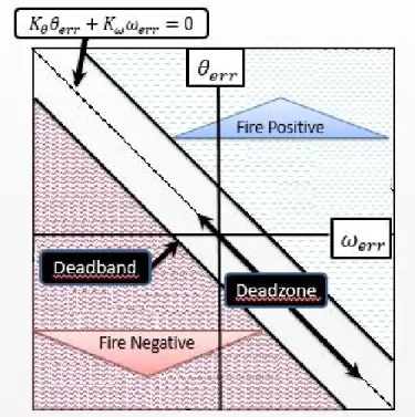
The most straightforward solution to the problem of Jetpack or SPHERES atti-tude control is to use thrusters for attiatti-tude control, since they are already necessary for position control. This was the solution implemented in NASA’s MMU and SAFER astronaut mobility units. Thrusters in the MMU, SAFER and proposed Jetpack are discrete on-off actuators with attitude control defined by a phase plane controller like the one in Figure 1-9. In phase plane control, allowable bounds for attitude error and sometimes angular rate error are selected; thruster firings for attitude control only occur if those error bounds are exceeded. What results is a deadband around the desired attitude (and angular rate if angular rate errors are selected). Inside this deadband, the system is allowed to drift until a large enough attitude (or angular rate) error accumulates. In this type of control implementation, propellant use is
3A solar sail or other non-rocket alternative to propulsion for translation and position control is
far from being practical at this time, especially since high thrust (as compared with solar radiation pressure) is required for quick translation times in human EVAs or SPHERES testing aboard the ISS
traded with pointing accuracy since more thruster firings are necessary to maintain a tighter deadband. In the MMU, the attitude deadband corresponds to attitude error alone and is adjustable between 0.5 and 2.0 degrees [11]. This deadband selection corresponds to attitude errors of 0.25 and 1.0 degree, respectively, since the total al-lowable error is equivalent to half of the selected deadband. The SAFER is designed along the same principles and has a fixed deadband of 2.0 degrees [14] correspond-ing to an allowable attitude error of 1.0 degree. The SPHERES system is designed specifically to allow for any conceivable control implementation and so a variety of thruster attitude control deadbands might be implemented for future applications.
Figure 1-9: Phase plane controller for attitude control with thrusters. Al-lowable bounds for errors in attitude, θerr, and angular rate, ωerr, are selected and
thruster firings only occur should the deadband defined by these bounds is exceeded. For a controller with proportional gain Kθ and differential gain Kω, no controller
output is commanded along the dotted line.
The problem of a deadband cannot be completely avoided by using an internal torquing mechanism like CMGs for attitude control. There will always be a limit to the minimum torque deliverable by an attitude actuator suite, as there will always be a limit to the sensitivity and time-resolution of inertial sensor measurements that
are used in a control law for attitude.4 The advantage of using CMGs is that the
deadband can be significantly reduced without fear of eliminating control authority as in the case of on-off thrusters. One reason is that CMGs provide a range of torques as opposed to the fixed torque delivered provide a minimum torque to the system that is less than the torque deliverable by a thruster pair (even with fast-acting solenoids to actuate thrusters, the torque delivered is not throttled, but instead delivered in discrete increments as defined by minimum on-times).
As is the case for any phase plane control implementation, drift resulting from a deadband practically defines the platform stiffness an astronaut pilot or a researcher of the SPHERES program might expect. Narrowing the deadband would increase the system’s stability, but at the expense of increased actuation; for thrusters, this results in increased fuel consumption, and for CMGs this results in increased battery energy consumption. Because on-off gas thrusters are not throttleable, tuning of control inputs can only be achieved by altering thruster on-times. CMGs, by contrast, can provide a range of torques to the system as defined by the minimum and maximum gimbal rates.
Practically, lower torque control inputs allow for narrower deadbands without fear of runaway consumable use. Of course, the capability to provide large torque control inputs is desired for impulse disturbance rejection and to achieve slews for extended mass configurations. Ideally, then, a tunable torque magnitude is desirable, which can be accomplished with CMGs and which cannot be accomplished with thrusters. In addition, a CMG array’s collective angular momentum provides a gyroscopic stiff-ness to the system that reduces the effect of external torques, thereby decreasing the control demands of the attitude control system to achieve precise pointing. Gyro-scopic stiffness can be understood simply as the conservation of angular momentum. A disturbance torque applied for a given amount of time is nothing more than a
con-4The selection of an inertial measurement unit (IMU) for a Jetpack or for SPHERES should take
into account the attitude control demands reflecting deadband objectives as well as those demands defined by translation control demands as well as payload demands that are as-yet undefined. The selection of sensors for MAJIC or the SPHERES system is outside the scope of this thesis; instead, the focus of this thesis is on the selection and evaluation of CMG actuators that might be used in conjunction with sensors that already exist (as in the case of SPHERES) or that are to be selected in future design studies (as in the case for MAJIC).


![Figure 1-10: Vectors and scalars for a single-gimbal CMG. Definition conven- conven-tions are borrowed from [6].](https://thumb-eu.123doks.com/thumbv2/123doknet/14682050.559477/50.918.273.650.150.490/figure-vectors-scalars-single-gimbal-definition-conven-borrowed.webp)