Publisher’s version / Version de l'éditeur:
Journal of the Soil Mechanics and Foundations Division, 95, SM6, pp. 1325-1334,
1970-01-01
READ THESE TERMS AND CONDITIONS CAREFULLY BEFORE USING THIS WEBSITE. https://nrc-publications.canada.ca/eng/copyright
Vous avez des questions? Nous pouvons vous aider. Pour communiquer directement avec un auteur, consultez la
première page de la revue dans laquelle son article a été publié afin de trouver ses coordonnées. Si vous n’arrivez pas à les repérer, communiquez avec nous à [email protected].
Questions? Contact the NRC Publications Archive team at
[email protected]. If you wish to email the authors directly, please see the first page of the publication for their contact information.
NRC Publications Archive
Archives des publications du CNRC
This publication could be one of several versions: author’s original, accepted manuscript or the publisher’s version. / La version de cette publication peut être l’une des suivantes : la version prépublication de l’auteur, la version acceptée du manuscrit ou la version de l’éditeur.
Access and use of this website and the material on it are subject to the Terms and Conditions set forth at
Building damage from expansive steel slag backfill
Crawford, C. B.; Burn, K. N.
https://publications-cnrc.canada.ca/fra/droits
L’accès à ce site Web et l’utilisation de son contenu sont assujettis aux conditions présentées dans le site LISEZ CES CONDITIONS ATTENTIVEMENT AVANT D’UTILISER CE SITE WEB.
NRC Publications Record / Notice d'Archives des publications de CNRC:
https://nrc-publications.canada.ca/eng/view/object/?id=424be12b-55bc-4986-ac3d-f209820e0c7d
https://publications-cnrc.canada.ca/fra/voir/objet/?id=424be12b-55bc-4986-ac3d-f209820e0c7d
L e s c a r a c t e r i s t i q u e s d e s s c o r i e s de haut-fourneau c r i t e s e t , s u r cette b a s e , on suggsre de n'utilise s c o r i e s d e s haut-fourneaux dont l e changement de long t e r m e peut 6 t r e t o l t r g . L'usage d'autres s c t e l l e s circonstances devrait & t r e prohibe a moins s e Ctre t t a b l i qu'elles auront un volume stable,
6879 November, 1969
BB\~na.uZED
SM 6Journal of the
SOIL MECHANICS AND FOUNI>ATIONS DIVISION
Proceedings of the American Society of Civil Engineers
BUILDING DAMAGE FROM EXPANSIVE S T E E L SLAG
BACKFILL^
By C a r l B. crawford,' M. ASCE, and Kenneth N. Burn'
Foundation f a i l u r e s caused by placing footings o r floor s l a b s on nn- compacted o r poorly compacted backfill a r e examples of poor construction control. F a i l u r e s resulting f r o m exvandina backfill a r e not s o e a s v t o an- ticipate. T h i s p a p e r d e s c r i b e s a c a s e r e c o r d o f building movements atiributed t o swellina backfill under a f l o o r slab. Althouah s a n d haclrfill had been s u e - cified, t h e backfill actually u s e d w a s s l a g f r o t i a s t e e l m i l l t h a t had, b e G r e its acceptance, undergone t e s t s a n d a p p e a r e d t o be f i r s t c l a s s m a t e r i a l f o r the purpose.
B l a s t f u r n a c e s l a g h a s been widely accepted i n t h e construction industry as a high aualitv m i n e r a l a e e r e e a t e . It i s commonlv u s e d in nortland c e m e n t
"
.
"
-- -
concrete, as highway b a s e c o u r s e o r r a i l r o a d ballast, and i n v a r i o u s bituminous mixes. Svecial ',expanded s l a p " obtained bv controllina t h e cooline v r o c e s s is used f o r t h e manufacture of lightweight concrete. In a i l t h e s e a p p i i i a t i o n s t h e common e x p e r i e n c e with i r o n b l a s t furnace s l a g a p p e a r s t o b e good. T h e r e-
a r e , unfortunately, o t h e r types of s l a g that do not p o s s e s s its good qualities, notably t h o s e produced i n open h e a r t h o r e l e c t r i c s t e e l f u r n a c e s . T h e consti- tuents of s t e e l f u r n a c e s l a g s v a r y widely; s o m e m a y b e s a t i s f a c t o r y , but theNote.-Di~cu~aion Open until April 1, 1970. Separate discussions should be sub- mitted f o r the individual papers in this symposium. To extend the closing date one month, a written request must be filed with the Exeoutive Seoretary, ASCE. This paper is part of the copyrighted Journal of the Soil Mechanics and Foundations Di- vision, Proceedings of the American Society of Civil Engineers, Vol. 95, No. SM6, November, 1969. Manuscript was submitted for review for possible publication on May 22, 1969.
aPresented at the August 26-28, 1968, ASCE Specialty Conference on Placement and Improvenrent of Soil to Support Structures, heidat MIT, Cambridge, Mass.
IASSt. Director, Division of Building Research, National Researohcouncil, Canada. aReSearch Offioer, Sail Mechanics Section, Division of Building Research, National Research Council, Canada.
1326 November, 1969 SM 6 user i s well advised t o check the properties carefully. Details of the com- position of slags a r e given l a t e r herein.
BUILDING
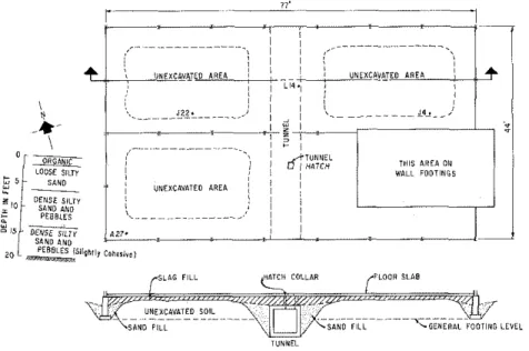
The building is located a t the Canadian end of the international bridge be- tween Michigan and Ontario a t SauU Ste. Marie. A building plan is shown in Fig. 1, together with a c r o s s section of the foundations. It is essentially a basementless, one-story structure with a partial second story. The exterior walls and interior columns a r e c a r r i e d on spread footings a t a depth of 5 ft. Footings on either side of a small service tunnel extend to depths of 9 f t and 10 ft. The excavated a r e a s were backfilledafier the foundations were in place,
,"I A R C A O l i WALL FOOTINGS
I
0 LiYii TUNNEL
FIG I -PLAN O F BUILDING AND SECTION THROUGH FOUNDATIONS SHOWINO UNEXCAVATED AREAS A M ) DISTRIBUTION O F SLAG F I L L BENEATH FLOOR SLAB and the concrete floor s l a b was cast on the compacted fill. General soil con- dltlons a r e a l s o shown on Flg. 1,Groundlevel is just
a
few feet above a near- by r i v e r .Construction of the tunnel and footings was completed during December, 1961 but with temperatures ranging a s low a s -30" F in January the operation was shut down and the footings were covered with an insulating layer of sand and straw. On February 5, 1962 the tunnel waterproofing was completed after much difficulty. On February 9th the daily report read "completedplacing and compacting granular fill along tunnel." This was probably sand backfill. Construction work was then suspended until about the middle of March, but by the end of April the fill was in place and ready for floor construction. The upper fill material i s slag from a local mill where no attempt was made to
SM 6 SLAG BACKFILL 1321 sevarate iron slag from steel slag. The exact thickness of s l a e i s not known. but i t probably va<iesfromafew inchesin unexcavated a r e a s t o m o r e than twa feet adjacent t o the tunnel and footings. Constructionof the building was com- .
pleted during the summer of 1962.
BUILDING PERFORMANCE
Early in 1963 cracking of the building was reported, and following a detailed inspection some r e p a i r s were made. During the summer of 1964 some of the
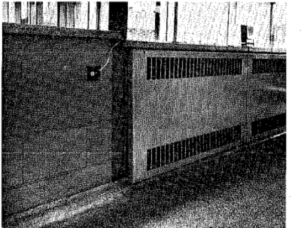
FIG. 2.-DIFFERENTIAL MOVEMENT ACROSS W N D O W S I L L
FIG. 3.-EVIDENCE O F MOVEMENT B E T W E E N COLUMN AND FI,OOH S L A B (MA- T P R N A STUDIOS)
1328 November, 1969 SM 6 window frames and interior metal and glass partitions began to buckle. Fig. 2 shows a section of window sill that was relevelled after it had become tilted upward on the inside. At this locationthe edge of the floor slab rests on a recessed shelf castinthe foundationwalland the interior cinder-block facine r e s t s on the floor slah. The window frame i s carried directly on the exterio; orecast slab wall. which r e s t s on the foundation wall. Differential movement between the inner facing and the outer wall caused the tipping of the window sill and some buckling of the window frame. An excavated section through the floor slab in 1965 revealed that the floor was resting on fill and that it had been raised 1/2 in. ahove the shelf on the foundation wall. By the end of 1967 the differential movement had exceeded 1 in. The cover for the heating unit in the background of Fig. 2 also i s attached to the outer wall, and it was nec- essary, therefore, to detach it at the bottom to prevent buckling a s the floor slab heaved.
Fig. 3 shows further evidence of differential movement between an in- terior column and the floor slah. The electrical conduit shown i s cast in the floor slab and turns up at the base of the column. Movement and slippage between the floor and column have caused relative movement between the
.
column and the conduit and sheared off the bolts fixing the outlet box to the column.FOUNDATION MOVEMENTS
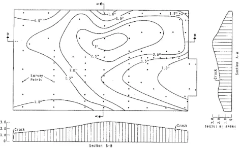
It was suspected a t firstthat some of the footings had been placed on frozen ground or had been heaved out of place during the winter shutdown in 1962. This explanation became untenable, however, a s time passed and movements continued. Regular level surveys initiated on October 3, 1963 showed that the outer walls and all of the structural columns were stationary and that the ground floor slab was rising. Observations on typical points on the floor slab a r e shown m Fig. 4 (the locations of these points a r e indicated on Fig. 1). Fia. 5 shows the locations of all the survev noints and the contours of heave over the entire floor slab. Swelling of thenatural subsoil was f i r s t suspected, but this was auicklv ruled out on the basis of i t s classification orooerties. Sometime in i964 i t was suggested that the slag backfill mighi have been swelling and the material was re-examined. It i s not clear what tests were c a r r i e d out, but it was concluded that the slag was practically inert and that i t s physical characteristics would probably not be altered by the addition of water.
In 1965 the Division of Building Research of the National Researcb Council of Canada was asked to investigate the nroblem. Durine an insoection of the
-
site inMay, 1965it became clear that swelllng of the slag backfill was the most vrobable explanation for the movements, based on the followina observations: Near the center of the buildinga
vertical hatch extends from-the roof of the tunnel through the floor slab; the space between (about 18 in.) i s occupied by slag. A horizontal crack about 1-1/2 in. wide all around the hatch collar in- dicated a relative upward movement of the floor slab f r o m the tunnel. Unless the slag had expanded vertically a void should have existed between the under side of the slab and the top of the fill, but removal of a small portion of the floor slab revealed that no void exists. The observed vertical movement represented about 7% of the original thickness of slag ahove the tunnel. By theSM 6 SLAG BACKFILL 1329 end of 1967 the crack had increased to 2 in. in width, indicating
a
vertical expansion of more than 9%.FIG. 4.-MEASURED HEAVE WITH TIME
FIG. 5.-CONTOURS O F HEAVE O F GROUND F L O O R (NOVEMBER, 1967)
SLAG TESTS
Samples of iron blast furnace (BF) and open hearth steel furnace
(OHF)
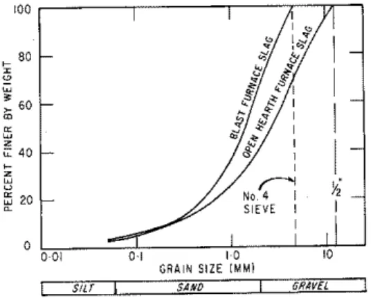
slags were obtained from the local steel mill. The BF slag was greenish- brown and made up of angular particles, all passing the No. 4 sieve. The OHF slag was grey to black, with an occasional white particle; all particles
1330 November, 1969 SM 6 passed the 1/2-in. sieve, but 30% was retained on the No. 4 sieve. Grain- s i z e curves a r e shown in Fig. 6.
F I G . &-GRAIN S I Z E O F SLAGS T E S T E D
FIG. 7.-AUTOCLAVE T E S T S P E C I M E N S
For t e s t purposes, samples were prepared a s follows: Sample A-natural
BF
slag (passing No. 4 sieve); Sample B-naturalOHF
slag with coarse particles (greater than No. 4 sieve) removed; and Sample C-naturalOHF
SM 6 SLAG BACKFILL 1331 Autoclave Tests. -Autoclave tests a r e qualitative. Test conditions a r e much more severe than "in service" conditions, but the results quickly reveal any potential chemical instability in the material that might result from moisture changes. Specimens were formed from the various slag samples by mixing with ordinary portland cement in the proportions of 3 parts slag t o 1 part cement. Two bars 1 in. sq in section and 6 in. in length were made from each of the three slag samples' using water cement ratios of just l e s s than 1:2 (+ 5%). Two reference specimens of Ottawa sand and portland cement were prepared in the same way.
The bars were cured at 21" C and 100% relative humidity for 65 hr, r e - moved from the molds, placed in the autoclave, and subjected t o steam a t
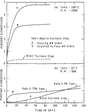
O p e n H e a r t h F u r n a c e S l a g A - P a l l i n g #4 S i e v e B - C r u s h e d to P a i n K4 S i e v e B l a s t F u r n a c e s l a g
I
l b l T e m p - 15-C R . H. - 90%1
R a t s 3 . 5 % Y e a r ,1
T i M E I N D A Y SFIG. 8.-TIME-EXPANSION T E S T S , B L A S T AND O P E N HEARTH F U R N A C E SLAGS 215" C a t a pressure of 300 psifor 3 hr. Except f o r minor variations this fol- lows the ASTM C151-64 standard test method.
When removed from the autoclave the specimens were in the conditions shown in Fis. 7. The intact bars on the richt were made from B F
slae:
thosein the foreground and to the left that have iisintegrated were made from OHF r slas. One of the reference specimens i s shownlvina in the foreground. Linear
.
-
I expansion of the OHF bars was about 10%.-
" Moderate Temperature Tests.-Cylindrical specimens of samples A,B and C were prepared by colnpactioi~ in bronze molds
2
in, in diam by 4 in. high1332 November, 1969 SM 6 and capped with aluminum discs set in plaster-of-paris. Following initial height measurements, the base of each specimen was allowed contact with free water throughaporous stone while the surrounding atmosphere was main- tained a t 100' C and 100% relative humidity. Periodic measurements of elon- gation, made with a dial gage, a r e shown in Fig. 8(aj. Apnroximatelv 3%to
5%
elongation was measuredfor the open hearth furnace siigs; the blast fur-nace slag showed very little change. Althou~h the inner surfaces of the molds had been greased, it i s suspected that swelling was somewhat reduced by side- wall friction.
Low Tem6erature Tests.-Three additional svecimens were tested a s for the moderate rem&,erarure tests, except old1 rlie suprounding lrniospllrre was mainrained at 15 C andanerox11n3rel\.90
;
relative humidity. Cnder these con- ditions the open hearth s ~ & expandediess, but was still expanding a t significant! rates after 5 months [Fig. 8(6)]. The blast furnace slag exhibed a small
movement during the initial stages, but the specimen cap became loose and ,
may have accounted for the slightmovements shownin Fig. 8 ( b ) . No movement was observed after 10 days.
PROPERTIES AND USES OF SLAG MATERIAL
The differences of properties between blast furnace slags and steel fur- nace slags a r e caused by differences in the refining processes. The reduction of iron ore in a blast furnace is a continuous overation that results in the production of a reasonably uniform slag in which calcium oxides and mag- nesium oxides a r e alwavs combined in silicateandalumino-silicate minerals. Steel production, on the other hand, is a batch process in whicb reactions a r e not always completed. This produces a nonuniform slag that may contain f r e e oxides of calcium and magnesium.
The chemical composition of open hearth slag i s generally variable and unpredictable. Fresh OH slag often has a substantial content of unslaked lime (CaOj, whicb will hydrate rapidly and cause large volume expansion. Much of the hydration and volume change occurs inafew weeks, s o that i t s volumetric stability can be improved by crushing and aging. The slag may also contain
a
significant quantity of magnesium oxide, which hydrates slowly causing volume changes that may continue for many years. Total volume changes of more than can be expected in severe cases.In this investigation samples of open hearth slag were obtained directly from the mill for comparison with slag material taken from under the floor slab of the building. X-ray diffraction patterns obtained by J. E. Gillott of the Division of Building Research showed similar composition. In approximate order of decreasing quantities it i s asfollows: calcium hydroxide, magnesium
.
oxide, magnesium hydroxide, calcite, quartz, and dolomite. The absence of calcium oxide and the nredominance of calcium hvdroxide indicates rawid and complete hydration of the oxide. The appreciable quantity of magnesium oxide indicates that hvdration of this oxide i s not vet comnlete and that this i s ihe ,probable basis
df
longterm swelling.The mechanism of hydration of calcium oxide to form calcium hydroxide has been investigated It was shownthat a linear expansion of 8% occurred during complete hydration of the oxide immersed in water. When, however,
SM 6 SLAG BACKFTLL 1333 hydration was caused by exposure to water vapor the linear expansion of an unconfined sample exceeded 100%. The immersiontest showedthat the volume of voids decreased during hydration anditwas deduced that calcium oxide was f i r s t dissolved and then recrvstallized. allowina the growth of crvstals within
-
original pore space. In the vapor test transformation occurs a s a solid state reaction pushing apart the constituents and maintaining a large void ratio.Results a r e not available f o r magnesinmoxide, but a similar interpretation can be readily visualized. This i s , however, a qualitative assessment. The . .
actual in-service expansion will depend on many factors, including initial density, confining pressure, degree of saturation and percentage of expansive oxides in the slag.
About 25,000,000 tons of blast furnace slag a r e used annually by the con- struction industry in the United States, apparently with complete success. Some 4 or 5,000,000 tons of steel furnace slag a r e also used in construction, '
' occasionallv with quite unsatisfactorv results. Exnerienced suaaliers of steel
.
.
furnace slag limit its use to open fills, unpaved roads and parking areas, railroad ballast or other ournoses wherevolume change will not cause suecial problems. Unf~rtunately,~these limitations a r e notwizely appreciated.
-
CONCLUSIONS
The relative vertical movement between the floor slab of the building and rhc rooi of Ill? sel.v!cerunnc-Illas occurred\%,lrh.ur m y ev~dsnce d i \'SKIS undr'r IIIE slab. Theslag ill1 u!lderthe sl3bmus1, rllertfore, have incrtased In volumc and it follows that the movement was caused by 'swelling of the slag. Other evidence of movement in the building i s consistent with this interpretation. Tests on the fill material confirm that it i s a steel Slag and that it has a swelling potential.
It i s shown that the autoclave test distinguishes eood material f r o m bad. Moderate and low temperature tests of the type desciibed allow estimates to be made of the potential swelling although theiruse i s limited by the time re- quired to achieve the c o m p l e t e v o l u r n ~ change. In addition the magnitude of measured swelling depends on the age of theslag and on its original chemical composition.
Little information on unsatisfactory slag materialappear s i n t h e literature, althoueh there i s
-
no doubt thatthearoblemarises when certain slaes a r e used-
in confined areas. It is hoped that this paper will direct attention to the serious damare that mav result f r a m the indiscriminate use of steel slag for backfill and t<us reduceproblems with its use..
Until evidence to the contrary i s forthcoming, it should be considered ha- zardous to use any slag exceptblast furnace slag for fill in confined spaces or where long-term volume changes cannot be tolerated.
ACKNOWLEDGMENTS
The writers greatly appreciate the complete cooperation of the consulting architects Somerville, McMurrich and Oxley of Don Mills, Ontario, repre- ,, sented by P. L. E. Goering, of the structural engineers E. A. Cross and
Associates of Toronto, and of the Maintenance Engineer of the International Bridge Authority, D. D. Dell. The paper i s published with the approval of the
1334 November, 1969 SM 6 consulting engineer r e p r e s e n t i n g the owner, C. H. Gronquist of Steinman, Boyn- ton, Gronquist and London of New York, a n d of R. F. Legget, D i r e c t o r of the Division of Building R e s e a r c h of t h e National R e s e a r c h Council of Canada.
APPENDIX.-REFERENCE
1. Ramachandian, V. S., Sereda. P. 1.. and Feldman, R . F., "Mechanism of Hydration of Calcium Oxide," Noture(United Kingdom), Vol. 201, No. 4916, Jan. 18, 1964, pp. 288-289.