HAL Id: tel-02952953
https://tel.archives-ouvertes.fr/tel-02952953
Submitted on 29 Sep 2020
HAL is a multi-disciplinary open access
archive for the deposit and dissemination of
sci-entific research documents, whether they are
pub-lished or not. The documents may come from
teaching and research institutions in France or
abroad, or from public or private research centers.
L’archive ouverte pluridisciplinaire HAL, est
destinée au dépôt et à la diffusion de documents
scientifiques de niveau recherche, publiés ou non,
émanant des établissements d’enseignement et de
recherche français ou étrangers, des laboratoires
publics ou privés.
Design for Manufacturing and Skin-skeleton Models
Elnaz Asadollahiyazdi
To cite this version:
Elnaz Asadollahiyazdi. Integrated Design of Additive Manufacturing Based on Design for
Manufac-turing and Skin-skeleton Models. Materials and structures in mechanics [physics.class-ph]. Université
de Technologie de Troyes, 2018. English. �NNT : 2018TROY0026�. �tel-02952953�
THESE
pour l’obtention du grade de
D
OCTEUR
de l’U
NIVERSITE
DE
T
ECHNOLOGIE DE
T
ROYES
Spécialité : MATERIAUX, MECANIQUE, OPTIQUE ET NANOTECHNOLOGIE
présentée et soutenue par
Elnaz ASADOLLAHIYAZDI
le 21 septembre 2018
Integrated Design of Additive Manufacturing based on Design for
Manufacturing and Skin-skeleton Models
JURY
M. A. BERNARD PROFESSEUR DES UNIVERSITES Président
M. V. DHOKIA ASSISTANT PROFESSOR Rapporteur
M. J. GARDAN PROFESSEUR ASSISTANT Directeur de thèse
M. P. LAFON PROFESSEUR DES UNIVERSITES Directeur de thèse
M. L. ROUCOULES PROFESSEUR DES UNIVERSITES Rapporteur
Mots clés : prototypage rapide, conception technique, procédés de fabrication, analyse du cycle
having you in my life. This work is also dedicated to my parents, Asadollah and Tahereh, who have always loved me unconditionally and whose good examples have taught me to work hard for the things that I aspire to achieve.
Integrated design of Additive Manufacturing based on Design For Manufacturing and skin-skeleton models
Abstract
Nowadays, Additive Manufacturing (AM) evolves the manufacturing world by its capabilities for production of the complex shapes layer by layer. Design For Manufacturing (DFM) approach helps to overcome the AM constraints and mastering product features in product lifecycle. Several studies are devoted to integrated design approach for AM, but there is no approach that considers all product life cycle steps in optimization level for product and manufacturing process. So, this thesis provides a DFM approach for AM to investigate simultaneously different attributes, constraints, and criteria of design and manufacturing in product definition. Skin-Skeleton approach models the first definition of product and AM. It contains functional analysis, usage model, and manufacturing model. In this work, a novel interface processing engine as an interface between product and manufacturing model is developed through analysis of AM technologies and their parameters and criteria. This engine relies on a bi-objective optimization problem to minimize production time and material mass under limitation of mechanical properties and roughness of the product to obtain the optimal manufacturing parameters. This methodology permits to define the product model. The approach is implemented into Fused Deposition Modeling to verify the methodology through two case studies.
Keywords: rapid prototyping, technical design, manufacturing processes, life cycle analysis,
multi-criteria decision making, mathematical optimization
Résumé
Aujourd’hui, la fabrication additive (FA) fait évoluer le monde de la fabrication grâce à ses capacités de production de formes complexes couche par couche. L’approche de conception pour la fabrication (DFM) aide à considérer les contraintes de FA et à maîtriser les caractéristiques du produit dans la gestion de son cycle de vie. Plusieurs études sont consacrées à l’approche de conception intégrée pour la FA, mais aucune approche ne prend en compte toutes les étapes du cycle de vie du produit dans le niveau d’optimisation de sa conception et de sa fabrication. Ainsi, cette thèse fournit une approche DFM pour la FA afin d’étudier simultanément différents attributs, contraintes et critères de conception et de fabrication dès la définition du produit. L’approche Peau-Squelette modélise la première définition du produit. Il contient une analyse fonctionnelle, un modèle d’usage et un modèle de fabrication. Dans ce travail, un nouveau moteur de résolution, qui agit à l’interface du modèle de produit et du modèle de fabrication, est proposé grâce à l’analyse des technologies FA et de leurs paramètres et critères. Ce moteur repose sur un problème d’optimisation bi-objectif pour minimiser le temps de production et la masse du matériau en proposant les solutions optimales pour les propriétés mécaniques et la rugosité du produit. Cette méthodologie permet de définir le modèle de produit. L’approche est mise en œuvre à travers une première technologie de dépôt par fil fondu (FDM) pour la production de deux études de cas.
Mots clés : prototypage rapide, conception technique, procédés de fabrication, analyse du cycle de vie,
décision multicritère, optimisation mathématique
Institut Charles Delaunay (ICD)- Laboratory of Mechanical Systems and Simulta-neous Engineering (LASMIS)
First and foremost, I would like to express my most sincere gratitude to my supervisors, Pr. Pascal LAFON and Dr. Julien GARDAN for their excellent support and guidance during my research work at LASMIS laboratory and EPF Graduating School of Engineering. Thanks to their priceless advice in scientific research, I have overcome many difficult problems of my thesis.
I would like to acknowledge Pr. Lionel RECOULES and Dr. Vimal DHOKIA who have accepted to read and examine my dissertation. Thank you for your brilliant comments and suggestions. I would also like to thank the members of the jury, Pr. Alain BERNARD and Pr. Nadège TROUSSIER for having accepted to be part of the jury and for their remarks and interesting questions in my PhD defense.
I am so grateful to the EPF Graduating School of Engineering of Troyes which provides possibility for me to study here and to use their Additive Manufacturing laboratory. I would like to show my gratitude to my EPF colleagues for their warmly welcoming and allowing me to join them.
I acknowledge my colleagues in the LASMIS lab, particularly Laurent DANIEL which helped me for 3D printing. I also thank Dr. Pierre-Antoine ADRAGNA for our discussion on Additive Manufacturing characteristics. I am thankful of my friends, Ali RIDA, Kim Trong NGUYEN, Yuchen ZHAO, and Li YIZHUO, and Van Tuan DANG for their support and exchanging knowledge and skills.
I am grateful to thank you all Iranian students in Troyes for our good time after scientific works, exchanges of knowledge, skills during my study which helped enrich the experience.
I gratefully acknowledge the Grand-Est region in France and the European Development Fund regional (ERDF) for their financial supports during this thesis.
Last but not least, I would like to thank my family and my best friends for their support and encouragement during the time far away from home. I must acknowledge my dear parents, Asadollah and Tahereh, and my lovely husband, Mohsen, without whose love and encouragement, I would not have finished this thesis.
Abstract v
Acknowledgment vii
Table of contents ix
List of Tables xiii
List of Figures xv
List of Abbreviations xix
List of Symbols xxi
I
English Version
1
Introduction 3
Background and motivation . . . 3
Problem statement . . . 4
Objectives . . . 5
Dissertation outline . . . 6
1 Integrated Design and Additive Manufacturing: state of the art 9 1.1 Introduction . . . 10
1.2 Product Life-cycle Management (PLM) . . . 11
1.3 Concurrent Engineering . . . 12
1.4 Design process . . . 13
1.4.1 Systematic design . . . 13
1.4.2 Integrated design . . . 14
1.4.3 Design For Manufacturing (DFM) . . . 17
DFM Implementation: Skin-Skeleton approach . . . 19
1.5 Additive Manufacturing . . . 23
1.5.1 AM standard formats . . . 24
STL: . . . 26
AMF: . . . 27 ix
1.5.2 Additive Manufacturing advantages and disadvantages . . . 28
AM advantages: . . . 29
AM disadvantages: . . . 31
1.5.3 Additive Manufacturing applications . . . 34
1.5.4 Additive Manufacturing technologies . . . 35
Laser technologies:. . . 37
Flash technologies:. . . 39
Extrusion technologies: . . . 40
Binder jetting technologies: . . . 42
Lamination and Cutting technologies: . . . 44
1.5.5 Additive Manufacturing attributes and criteria . . . 46
1.6 Design For Additive Manufacturing . . . 47
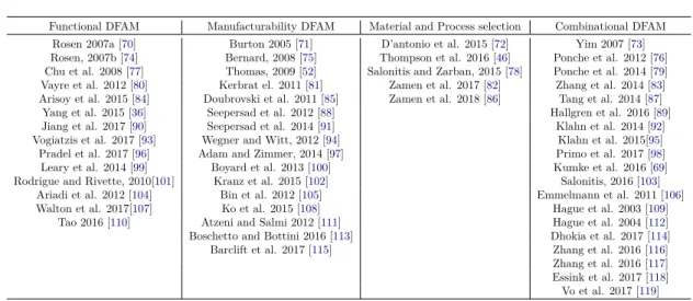
1.6.1 Functionality DFAM: . . . 48
1.6.2 Manufacturability DFAM: . . . 50
Manufacturability verification: . . . 50
Manufacturability quantification: . . . 53
Manufacturability optimization: . . . 53
1.6.3 Meta-Models, Design Of Experiments (DOE): . . . 57
1.6.4 Material and process selection based DFAM: . . . 60
1.6.5 Combination of functionality and manufacturability DFAM: . . . 60
1.7 Research gaps: . . . 64
1.8 Summary . . . 65
2 DFM-Skin and Skeleton approach for AM: Proposed methodology 67 2.1 Introduction . . . 67
2.2 DFM-Skin and Skeleton approach for AM: Proposition 1 . . . 70
2.2.1 Functional analysis . . . 75
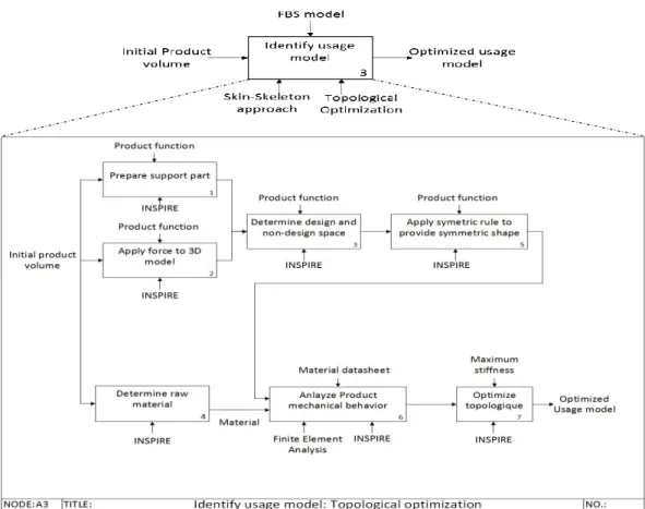
2.2.2 Usage model . . . 75
2.2.3 Manufacturing model . . . 78
Additive Manufacturing criteria and constraints . . . 84
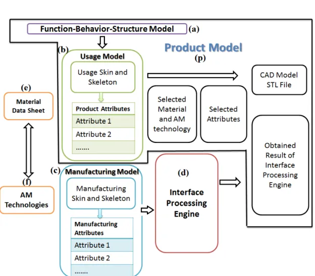
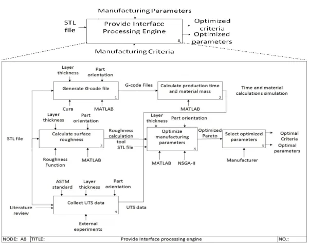
2.2.4 Interface Processing Engine. . . 86
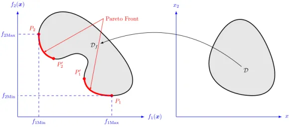
Bi-objective optimization problem . . . 89
Solving Procedure . . . 92
2.2.5 Product model . . . 95
2.3 DFM-Skin and skeleton approach for AM: Proposition 2: . . . 95
2.4 Summary . . . 98
3 Application into Fused Deposition Modeling 101 3.1 Introduction . . . 102
3.2 DFM-skin and skeleton approach based on proposition 1 for case study 1: Bag hook 103 3.2.1 Functional analysis for bag hook . . . 104
3.2.2 From usage model to 3D model for bag hook . . . 105
Usage model identification of bag hook: . . . 105
3.2.3 Optimized 3D model . . . 107
3.2.4 FDM manufacturing model . . . 110
3.2.5 Interface processing engine for bag hook to fabricate by FDM: . . . 115
Initial fixed parameters for interface processing engine of bag hook. . . 116
FDM criteria . . . 119
3.2.6 Final bag hook product model . . . 140
3.3 DFM-skin and skeleton approach based on proposition 2 for case study 1: Bag hook 142 3.4 DFM-skin and skeleton approach under proposition 1 for case study 2: Wheel spindle 143 3.4.1 Functional analysis for wheel spindle . . . 147
3.4.2 From usage model to 3D model for wheel spindle . . . 148
3.4.3 FDM manufacturing model . . . 150
3.4.4 Interface Processing Engine of wheel spindle . . . 152
Results . . . 155
3.4.5 Final spindle product model . . . 159
3.5 DFM-skin and skeleton approach based on proposition 2 for case study 2: Wheel spindle . . . 160
3.6 Summary . . . 162
4 Conclusions 163 4.1 Conclusions . . . 165
4.2 Perspectives and future works. . . 165
4.2.1 Short-term perspectives . . . 166
4.2.2 long-term perspectives . . . 167
II
French version
169
French Summary 171 Introduction . . . 171Problématique et objectifs de l’étude : . . . 172
Organisation du mémoire . . . 173
Conception intégrée et fabrication additive : état de l’art . . . 174
L’approche DFM-peau et squelette pour FA : Méthodologie proposée . . . 180
DFM-peau et squelette pour FA basé sur la proposition 1 : . . . 181
Modèle FBS . . . 182
Modèle d’usage . . . 182
Modèle de fabrication . . . 183
Moteur de traitement d’interface : . . . 188
Modèle du produit. . . 192
L’approche DFM-peau et squelette pour FA basée sur la proposition 2 : . . . 192
L’application et validation dans la modélisation des dépôts de file chaude . . . 194
Étude de cas 1 : crochet de sac . . . 195
Étude de cas 2 : fusée de la roue . . . 208
Conclusions . . . 216
Bibliography 219
Appendix A: FDM softwares 233
Appendix B: G-code files 237
Appendix C: modeFRONTIER 241
Appendix E: List of publications 247
Refereed publications . . . 247
1.1 Design For X classification [17, 16, 18] . . . 16
1.2 STL format advantages and disadvantages . . . 28
1.3 AM Classification provided by ASTM standard [54]. . . 36
1.4 AM technologies accuracy [37]. . . 46
1.5 DFAM approach classification . . . 48
2.1 Different AM technologies parameters . . . 82
2.2 AM Parameters and criteria and their degree of importance derived from literature analysis (30 articles) . . . 83
3.1 Bag hook specifications . . . 104
3.2 Parameters and criteria derived from literature analysis for FDM (131 articles) . 112 3.3 Relation between usage and manufacturing attributes . . . 118
3.4 Orientation types and its UTS data for different layer thickness . . . 129
3.5 Bi-objective optimization problem parameters . . . 130
3.6 NSGA-II defined parameters in Modefrontier . . . 134
3.7 NSGA-II defined parameters . . . 135
3.8 Optimal solutions for continuous bi-objective optimization problem . . . 138
3.9 Optimal solutions for discrete bi-objective optimization problem . . . 138
3.10 Pareto front for wheel spindle for continous optimization problem. . . 158
3.11 Pareto front for wheel spindle for discrete optimization problem. . . 159
4.1 Classification d’approche DFAM . . . 177
4.2 Paramètres et critères de FA et leur degré d’importance dérivé de l’analyse de la littérature (30 articles) . . . 186
4.3 Paramètres et critères dérivés de l’analyse de la littérature pour FDM . . . 199
4.4 Fabrication paramètres. . . 200
4.5 Types d’orientation et ses données UTS pour différentes épaisseurs de couche . . 203
4.6 le front Pareto de problème d’optimisation continue bi-objectif pour le crochet . 207 4.7 le front Pareto de problème d’optimisation discrète bi-objectif pour le crochet . . 207
4.8 Le front Pareto pour fusée de roue pour un problème d’optimisation continue . . 215
4.9 Le front Pareto pour fusée de roue pour un problème d’optimisation discrète . . 216
1.1 Comprehensive version of general integrated design model [15]. . . 14
1.2 Different design process- a) Systematic Design b) integrated Design c) Integrated design presented by LASMIS [12] . . . 15
1.3 Design For X [3] . . . 16
1.4 Design For Manufacturing [3] . . . 18
1.5 Skin and Skeleton illustration for a "U" Magnet [31] . . . 21
1.6 FBS model framework [32]. . . 22
1.7 AM engineering and manufacturing cycle [37] . . . 25
1.8 Data flow in STL file creation [40] . . . 26
1.9 STL format and its triangles [37] . . . 27
1.10 Laser technologies (SLA-SLM-SLS) [37] . . . 39
1.11 Flash technology (Masking) [37]. . . 40
1.12 Extrusion technologies [37]. . . 42
1.13 Binder Jetting technologies (MJM-3DP) [37] . . . 43
1.14 Laminated Object Manufacturing (LOM) [65] . . . 45
1.15 Stratoconception [66]. . . 45
1.16 Pareto front of a bi-objective optimization problem . . . 56
1.17 Non-dominated Sorting Genetic Algorithm-II (NSGA-II). . . 58
1.18 Statistical analysis of DFAM approaches . . . 65
2.1 Proposition 1 . . . 69
2.2 Proposition 2 . . . 70
2.3 General structure of DFM-Skin and Skeleton approach for AM . . . 72
2.4 How to produce a product due to DFM- Skin-skeleton approach. . . 74
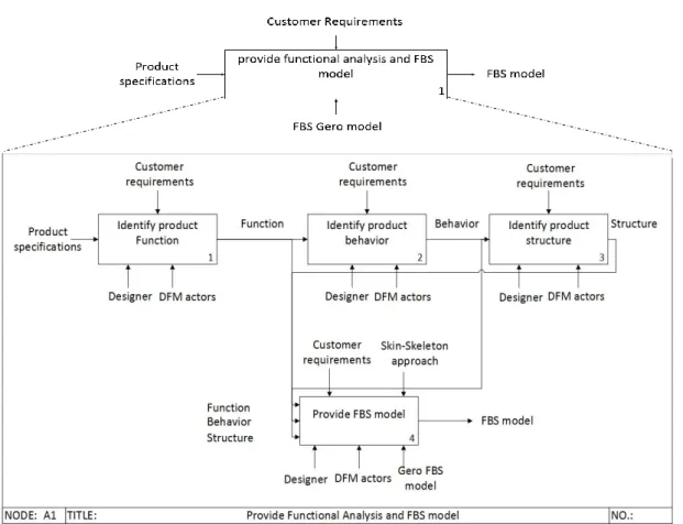
2.5 Provide functional analysis and FBS model . . . 76
2.6 Provide initial product model . . . 76
2.7 Identification of usage model . . . 77
2.8 Provide CAD model . . . 78
2.9 STL file creation . . . 79
2.10 Identify manufacturing model . . . 79
2.11 Identify manufacturing parameters . . . 81
2.12 AM product structure [154, 155] . . . 81
2.13 (a) Chordal error [166]- (b) Staircase error [167]. . . 85
2.14 Providing an interface processing engine . . . 87 xv
2.15 Decision variables: angles between parts and the axis of x,y and z [169]- Layer
thickness. . . 89
2.16 Orientation types [170] . . . 90
2.17 ModeFrontier workflow to solve bi-objective optimization problem . . . 93
2.18 NSGA-II procedure for solving the optimization problem. . . 94
2.19 Product model . . . 95
2.20 Providing usage skeleton by power crust algorithm . . . 96
2.21 Power Crust algorithm procedure on a two dimensional example (a) An object with its medial axis-(b) The Voronoi diagram-(c) Inner and outer pollar balls-(d) The power diagram cells of the poles-(e) power crust and power shape of its interior solid [173] . . . 97
3.1 Fused Deposition Modeling [175] . . . 103
3.2 FBS model defined for bag hook . . . 104
3.3 First definition of hook for topological optimization. . . 106
3.4 Symmetric optimized bag hook . . . 108
3.5 Topological optimization procedure and optimized usage model as result . . . 108
3.6 CAD model obtained according to usage model . . . 109
3.7 Manufacturing Skin-Skeleton . . . 110
3.8 STL file of bag hook . . . 111
3.9 Different parts of produced bag hook . . . 111
3.10 DFM-Skin and Skeleton approach for FDM . . . 117
3.11 Roughness parameters [182] . . . 121
3.12 R1 and R2 [164]. . . 122
3.13 Roughness values for different deposition angles and resolution . . . 122
3.14 (a) Schematic of filament section (b) Deposited filament parameters [127] . . . . 125
3.15 Accuracy function [181] . . . 126
3.16 Deposition angle for the triangle [184] . . . 127
3.17 Oriented facet of triangles STL of a FDM product [185] . . . 127
3.18 Hook facet deviation . . . 128
3.19 UTS data for different values of layer thickness and orientation derived from literature129 3.20 Bag hook structure and function . . . 131
3.21 Defined orientation for bag hook in discrete problem . . . 133
3.22 Result obtained by Modefrontier . . . 134
3.23 Optimal solutions obtained by NSGA-II for bi-objective optimization problem for bag hook . . . 136
3.24 Final product fabricated by AM . . . 141
3.25 (a) Usage Skeleton by power crust algorithm (b) Usage skeleton as material flow (manually). . . 143
3.26 Broken spindle as problem statement in the second case study. . . 144
3.27 Vehicle dimensions and functionality . . . 145
3.28 The force applied to wheels . . . 145
3.29 The force applied to spindle . . . 146
3.30 FBS model for wheel spindle . . . 148
3.31 Initial spindle volume . . . 149
3.32 Usage model for spindle coming from topological optimization. . . 150
3.33 3D model of spindle . . . 151
3.34 Spindle functional parts . . . 151
3.36 Manufacturing model and spindle structure in different raster (infill) direction. . 153
3.37 The initial model for Finite Element Analysis . . . 154
3.38 Finite Element Analysis of new wheel spindle . . . 154
3.39 Optimal solutions obtained by NSGA-II for wheel spindle . . . 156
3.40 Produced wheel spindle by FDM . . . 160
3.41 Usage Skeleton of wheel spindle by power crust algorithm . . . 161
II.1 Présentation du processus de conception, a. Conception systématique, b. Conception intégrée et simultanée, c. Conception intégrée selon LASMIS-UTT. . . 175
II.2 Définition schématique de la conception pour la fabrication (DFM) [12] . . . 175
II.3 Analyse statistique des approches DFAM . . . 178
II.4 Modèle FBS de crochet . . . 196
II.5 Du modèle d’usage au modèle 3D . . . 197
II.6 Le modèle peux-squelette de fabrication . . . 198
II.7 Types de l’orientation [170] . . . 203
II.8 Solutions optimales obtenues pas NSGA-II pour le crochet de sac . . . 205
II.9 Fusée de la roue cassée . . . 208
II.10 Dimensions du véhicule et fonctionnalité . . . 209
II.11 La force appliquée aux roues . . . 210
II.12 Modelé FBS de la fusée de la roue . . . 211
II.13 Modèle 3D de la fusée . . . 211
II.14 Le front Pareto obtenues par NSGA-II pour la fusée de roue. . . 213
A.1 Makerbot custom settings . . . 234
A.2 Cura 2.5 custom setting . . . 235
A.3 Slic3r custom setting . . . 236
B.1 G-code file description . . . 238
B.2 G-code file. . . 239
C.1 ModeFrontier Software environment . . . 242
D.1 Finite Element Analysis (FEA) for wheel spindle . . . 244
ABS Acrylonitrile Butadiene Styrene
AHP Analytical Hierarchy Proces
ALM Additive Layer Manufacturing
AM Additive Manufacturing
AMF Additive Manufacturing File
ANSYS ANalysis SYStem
ASTM American Society for Testing Material
CATIA Computer-Aided Three-dimensional Interactive Application
CILP Continous Liquid Interface Production
CJP Color Jet Printing
DDM Dough Deposition Modeling
PLM Product Lifecycle Management
CAE Computer Aided Engineering
CAD Computer Aided Design
CaCODE Computer aided Consumer DEsign
CDFAM Customized Design For Additive Manufacturing
CE Concurrent Engineering
CTscan Computed Tomography scan
CMM Coordinate Measuring Machine
DFA Design For Assembly
DFAM Design For Additive Manufacturing
DFM Design For Manufacturing
DFX Design For X
DFS Design For Safety
DLP Digital Light Processing
DMD Direct Metal Deposition
DMLS Direct Metal Laser Sintering
DOE Design Of Experiment
ERP Entreprise Resource Planning
FBS FuncTion Behavior Structure
FDM Fused Deposition Modeling
FFF Fused Filement Fabrication
FRs Functional Requirements
FTI Film Transfer Imaging
FV Functional Volume
HPGL Hewlett-Packed Graphics Language
HSM High Speed Machining
IFF Ion Fusion Formation
IGES Initial Graphic Exchange Specification
JSON JavaScript Object Notation
LENS Laser Engineered Net Shaping
LMJ Liquid Metal Jetting
LOM Laminated Object Manufacturing
MAT Medical Axis Transformation
MATLAB MATrix LABoratory
MCDM Mlti Criteria Decision Making
MD Manufacturing Direction
MES Manufacturing Execution System
MOGA Multi-Objective Genetic Algorithm
MPM Manufacturing Process Management
MRI Magnetic Resonance Imaging
NSGA-II Non-dominated Sorting Genetic Algorithm-II
PC PolyCarbonate
PDM Product Data Management
PLA PolyLactic Acid
PPSF PholyPhenylSulFone
PSO Particle Swarm Optimization
RAM Random Access Memory
RSM Response Surface Methodology
SADT Structured Analysis and Design Technique
SPEA Strength Pareto Evolutionay Algorithm
SLA StreoLithogrAphy
SLC StreLithography Contour
SLM Selective Laser Melting
SLS Selective Laser Sintering
STL Standard Tessellation Language
TO Topological Optimization
UV Ultra Violet
XML eXtensible Markup Language
3D Three Dimensional
3DP Three Dimensional Printing
List of Symbols
xinf Lower bound of decision variables
-xsup Upper bound of decision variables
-f(x) Optimization objective function vectors
-p Numbers of optimization objective function
-m Numbers of optimization inequality constraint function
-l Numbers of optimization equality constraint function
-fi(x) Optimization objective function for i=1,...,p
-cj(x) Optimization constraint function for i=1,...,m,..,l
-x∗ Optimal solutions vector
-D Solution space
-Df Pareto front
-wi ithWeight for Objective function
-Lt Layer thickness mm
α Deposition angle ◦
θx Orientation angle along x-axis ◦
θy Orientation angle along y-axis ◦
θz Orientation angle along z-axis ◦
x Decision variables vector [◦,◦,◦, mm]
ub Upper bound of AM decision variables [◦,◦,◦, mm]
lb Lower bound of AM decision variables [◦,◦,◦, mm]
R1 Radius of fillet in layers 0.045
R2 Radius of corner in layers 0.01
w Dimensionless parameter of roughness 0.2
d Nozzle diameter of printer 1.75 mm
σMax Maximum mechanical stress
ρABS ABS density 1.04 g/cm3
Ra Surface roughness µm
e extrusion width mm
E Extruded material mm
F Speed mm min−1
L Coordinate distance mm
y(x) Roughness profile value
-l Evaluation length mm
yc Center line position mm
Tj jthtraingle of STL file
-n normal vector
-z Vertical direction vector
-nTj normal vector of triangle j
-αTj Deposition angle of triangle j
-Rx Rotation matrix along x-axis
-Ry Rotation matrix along y-axis
-Rz Rotation matrix along z-axis
-r radius filament mm
f spacing filament mm
Ω Filament semicircle for vertical walls
-Σ Filament semicircle for inclined surface
-h Profile height mm
∆h Dimensional deviation mm
V1, V2, V3 A triplet of the vertices for a triangle of STL file -V1j, V2j, V3j A triplet of the vertices for a triangle j of STL file
-FT 1 Total force for first case study N
Mf Bending moment N m
I Second moment N m
a × b × h Hook bag dimensions mm*mm*mm
FF The force applied to front wheel N
FB The force applied to back wheel N
m Kid weight 20 kg
G The force created through kid weight N
as The distance between front wheel and car seat 200 mm
bs The distance between back wheel and car seat 275 mm
dw The distance between back and front wheels 475 mm
2cs The distance between two front wheels 325 mm
2ds The distance between two front wheels 295 mm
e, f, L Spindle dimensions 43.42 mm, 39.8 mm, 33.6 mm
FL Triangular distributed force applied to spindle along L N m−1
FT 2 Total force applied to spindle (second case study) N
σyield(ABS) ABS tensile stress at yield 39 MPa σyield(Steel) Steel tensile stress at yield 250 MPa
Outline of the current chapter
Background and motivation 3
Problem statement 4
Objectives 5
Dissertation outline 6
Background and motivation
Nowadays, it is essential to respond to industrial challenges towards shorter lead times, lower cost, higher product quality, and better customer satisfaction. Concurrent Engineering (CE) became more important in the success of the companies as a solution for these issues. CE is a systematic approach which performs different tasks in the product and production development process which are then integrated and performed at the same time in parallel rather than in sequence. Integration of design and manufacturing constraints makes it possible to decrease the development lead time and enhances the product quality [1].
On the other hand, Additive Manufacturing (AM) which is derived from rapid prototyping, revolutionizes the industrial world. It creates the possibility to produce different versions of a product with a range of material with specific technologies. The product is manufactured from a 3D model through layer-by-layer manufacturing technology. The unique characteristics of AM encourage the producers to use these technologies, but there are some drawbacks that affect the production performance [2].
The product design and manufacturing for AM are different compared to the traditional 3
manufacturing processes and it creates new issues and concerns for industrial implementation. Until now, the link between design and manufacturing of additive techniques is often a STL format which does not contain the fabrication information. So, it is necessary to find a methodology to consider all these aspects together.
In the context of Concurrent Engineering and AM, this thesis is motivated to present an integrated design approach of AM.
Problem statement
In the research area of manufacturing of the products by AM, it is intended to investigate the following general problems:
• Suggest a general approach to formulate how to take into account the usage and AM constraints simultaneously in the product definition level.
• Provide an approach to analyze and model the AM process. To investigate these problems, we encounter some questions:
• How to model and optimize the product to fulfill the customer’s requirements?
• How to integrate the manufacturing step and its constraints in the design step to improve the product model in terms of cost, time, and quality?
• Which attributes and criteria are important in the product development process of the fabrication with AM?
• Which parameters of additive technologies have significant effects on the AM attributes, criteria and constraints and how to find the best manufacturing parameters?
• How to integrate all steps of the product development process in a general integrated design approach?
To handle the defined problems and answer to all these questions, it is necessary to present an integrated and complete approach addressing the attributes, capabilities, criteria, and constraints concurrently to provide an interoperable process in product life cycle management for AM.
Integration of design and manufacturing related to AM can facilitate its implementation as it is intended to consider the manufacturing process early in the product definition as an integrated design approach. The product model is completed through a 3D model, manufacturing information, and defined attributes through Design For Manufacturing (DFM) approach.
For this purpose, it is necessary to find a methodology toward an integrated design approach for AM. DFM approach was applied to traditional manufacturing processes through Skin-Skeleton approach in some studies [3, 4]. In this study, this skin-skeleton approach is chosen to model the first definition of the product as a usage model and manufacturing process as manufacturing model. This approach will be completed through an interface processing engine which is an interface between design and manufacturing in order to define the final product model. It is developed through the analysis of all AM technologies and identification of their parameters, criteria, and drawbacks to find the optimized product model.
Objectives
The objectives of this study are summarized as follows:
• Study and analysis of scientific researches related to concurrent engineering, design process and integrated design, Design For Manufacturing, and modeling the product in a general way.
• Investigate the different performed studies related to AM and its technologies.
• Present the contribution regarding the method and new scientific and technological directions in the integrated design approach for AM. The integrated design approach is provided in the product definition level and it gradually maps the product sepecifications to the final product model. It creates an interface between product model and manufacturing model which is a support for the designer in order to select the manufacturing process and to integrate its constraints and attributes as soon as possible during product development process.
Dissertation outline
This thesis is presented in the following four chapters:
Chapter 1: Integrated Design and Additive Manufacturing: State of the art
This chapter introduces the Additive Manufacturing and Integrated Design as the basic concepts of this thesis including background and status of the Concurrent Engineering, AM and product development in the industry. The presented approaches of Integrated Design for AM as the solutions to integrate AM attributes and constraints in design step to define a product model, as well as optimization approaches of AM criteria, are reviewed in this chapter. The literature analysis on the other proposed approaches is prepared which guides the research to the problems and research gaps.
Chapter 2: DFM-Skin and Skeleton approach for AM: Proposed methodology
This chapter describes the proposed methodology as DFM-Skin and Skeleton approach for AM. It provides an integrated approach for AM to consider simultaneously the AM characteristics, criteria, and drawbacks to find the final product model which consists of 3D model and the best manufacturing parameters for production. Skin-Skeleton approach is used to model the first definition of the product and manufacturing process. This methodology is developed based on two propositions. The propositions are different in terms of the methodes that are used for defining usage, manufacturing and interface models. They are developed through analysis of the requirements, design step, AM technologies and finally integration of these steps together to define the product through multi-criteria decision-making methods and multi-objective optimization approach.
Chapter 3: Application into Fused Deposition Modeling
The reliability of the proposed approach is highlighted through two case studies which will be produced by Fused Deposition Modeling as one of the most AM technologies. Firstly, this approach is verified through a case study as a bag hook, then, a more complex case study as a wheel spindle of a child car will be studied to utilize the AM capability to reuse a product by
replacing its broken part. The second case study shows the reliability of our proposed approch for other products.
Chapter 4: Conclusion
To complete this research, the discussion section will be provided to analyze the proposed approach. Then, the key conclusions and perspectives are given in this chapter to guide other researchers to continue their studies in this domain.
1
Integrated design and Additive Manufacturing:
state of the art
Outline of the current chapter
1.1 Introduction 10
1.2 Product Life-cycle Management (PLM) 11
1.3 Concurrent Engineering 12
1.4 Design process 13
1.4.1 Systematic design . . . 13
1.4.2 Integrated design . . . 14
1.4.3 Design For Manufacturing (DFM) . . . 17
1.5 Additive Manufacturing 23
1.5.1 AM standard formats . . . 24
1.5.2 Additive Manufacturing advantages and disadvantages . . . 28
1.5.3 Additive Manufacturing applications . . . 34
1.5.4 Additive Manufacturing technologies . . . 35
1.5.5 Additive Manufacturing attributes and criteria . . . 46
1.6 Design For Additive Manufacturing 47
1.6.1 Functionality DFAM: . . . 48
1.6.2 Manufacturability DFAM: . . . 50 9
1.6.3 Meta-Models, Design Of Experiments (DOE): . . . 57
1.6.4 Material and process selection based DFAM:. . . 60
1.6.5 Combination of functionality and manufacturability DFAM: . . . 60
1.7 Research gaps: 64
1.8 Summary 65
1.1
Introduction
Nowadays, Additive Manufacturing (AM) and its different technologies bring a new approach to produce many complex products with different materials. This manufacturing method is derived from Rapid Prototyping and it manufactures the products based on the 3D model in layer-by-layer manufacturing process through different technologies to process the material [5]. The advantages of AM encourage the manufacturers to use additive technologies, while it has some disadvantages and constraints [2]. These unique characteristics, advantages, disadvantages, and constraints require new design tools and practices in order to manage the design and manufacturing process. Also, designers are not completely free to create geometric shapes in this method, that is why several issues must be taken into account during design and manufacturing steps. It is necessary to choose the correct method of design and manufacturing simultaneously in Product Life Cycle Management. Also, it is essential to respond to industrial challenges towards shorter lead times, lower cost, higher product quality, and better customer satisfaction. For this aim, designers must utilize Concurrent Engineering aspects in AM implementation [6]. Concurrent Engineering (CE) helps to integrate design and manufacturing constraints to decrease the development lead time and enhances the product quality [3,1]. Design For Manufacturing (DFM) as one of the basic concept of CE helps designer and manufacturer to investigate the constraints and attributes of the manufacturing process in the design stage. Finally, it provides a product model by analysis of all attributes and constraints of functional analysis, design and manufacturing concurrently [7]. The remainder of this chapter is organized as follows: firstly, Product Life-cycle Management is described in section1.2. Concurrent Engineering, Design process and Design for Manufacturing are explained consequently in section1.3and 1.4. Then, section1.5discusses Additive Manufacturing
and its characteristics and technologies. Finally, Design for Additive Manufacturing approaches are reviewed in section 1.6. According to this literature analysis, the reserach gaps are identified in section1.7. Finally, this chapter will be finished by a summary of this chapter (section1.8).
1.2
Product Life-cycle Management (PLM)
Modern manufacturing systems are facing several challenges like shortened innovation lead-times, reduction of time to market, cost reduction, mass customization demands, more complex products, improving product quality, inventories subject to rapid depreciation and rapid fulfillment needs [8,
9]. New information systems are enabled to tackle the different challenges and allow them to show the product information over the whole product life cycle. The emergence of the PLM concept has generated these information systems. PLM is an information technology platform which is able to respond to the needs like reducing time-to-market, enhancing collaboration for global engineering teams, reducing development costs, improving customer satisfaction, and increasing the value of product portfolios [10].
The PLM concept links different product development stages including Computer Aided Engineering (CAE), Computer Aided Design (CAD), Product Data Management (PDM), Manu-facturing Process Management (MPM), Enterprise Resources Planning (ERP), etc. in a unique numerical chain. The target is to improve the manufacturing systems criteria like time-to-market, cost, and quality. Actually, there is no unique method which allows managing a project for the development of a product. It is very difficult because of the vast amount of information which comes from different trades [9].
The catchword of PLM is collaborative work within product design processes to integrate all the partners and all associated knowledge efficiently. Design needs to be defined as a collaborative process and can be optimized by allowing upstream integration of data, resources and knowledge. The actual collaborative design is often reduced to asynchronous data exchanges through Product Data Management (PDM), even if some people prefer to speak about "sharing" since the product is a mutual creation. Modeling design activities implies to take into account not only product but also process planning and the processes themselves [9].
and manufactured. The principal strategy which modified the sequential organization of work is called Concurrent Engineering (CE) [11]. Concurrent Engineering provides a vision to organize the product development as described in the next section.
1.3
Concurrent Engineering
Concurrent Engineering (CE) is an ideal environment for product development. One of the first general definitions of simultaneous engineering is that of Sohlenius, 1992 [1] who postulates that: "Concurrent engineering means a way of work where the various engineering activities in the product and production development process are integrated and performed as much as possible in parallel rather than in sequence ".
CE is the process of taking into account the needs of each different stages of the product life cycle simultaneously. It aims to integrate product life cycle knowledge earlier during the design process and different engineering activities must be integrated together and performed in parallel [3]. So, the iteration between the design activities which create the advantages in time, quality and cost is reduced. The strategy of CE is to integrate the material and manufacturing constraints into the design procedure as well as, tool utilization must be computer-based to ensure the desired accuracy [12].
CE involves two main areas including design process of the product and the constraints of the product life cycle arising from manufacturing, assembly, recycling, and maintenance. It allows investigating the entire life cycle of the product, from the first expression of the need to final service [3] in order to define a product. So, this approach reduces the iterations between design activities which create the advantages in time, quality, and the cost. The strategy of Concurrent Engineering is to integrate the material and manufacturing constraints into the design procedure by computer-based tool utilization to ensure the accuracy [12].
The CE objectives include improving quality, reducing cost, compressing cycle times, raising productivity and efficiency, and improving the social image. For achieving these objectives, a cooperative teamwork is needed between multiple disciplinary functions to consider all interacting issues in designing product, processes, and systems [7]. The strategies are used to integrate life cycle constraints into the early stages of the design process.
To manipulate the concepts and mechanisms of Concurrent Engineering, the scientific commu-nity formalizes them with design methods and they are provided according to the product design process. In the rest of this chapter, the design process will be presented in a general way with the different types of design including systematic and integrated design. Also, it is continued with the section of design methods for manufacturing.
1.4
Design process
The design is the most important stage in the product life cycle and Concurrent Engineering. It is essential to determine the design step in detail to define a product. Also, optimizing the design stage can reduce the total cost up to 70% thereby the production cost is optimized significantly [12].
There are several approaches for design. Firstly, the design is defined as a systematic process which includes the successive steps that performed without evaluation and considering the feedbacks. The second one is an integrated design which provides the design process as the integrated steps [12]. These types of design are defined as follow:
1.4.1
Systematic design
The systematic design is introduced by Beitz et al. 1996 [13] which classified the design process in four evaluation levels:
• Requirement analysis: This approach is started with the determination of the customer requirements and product specifications.
• Conceptual design: This step consists of definition of the specifications, determination of functional structure, functional principles, and evaluation of conception choices. • Embodiment design: It is including the definition of size and form, model and analysis
of these aspects of the product with together, optimizing the functions, evaluating and choosing the plots.
Figure 1.1 – Comprehensive version of general integrated design model [15]
fabrication methods, optimizing the performance and cost, preparing detailed drawing definition.
1.4.2
Integrated design
Integrated design is an approach considering all aspects of the product life cycle in its design like functions, analysis, manufacturing, assembly, recycling, etc. [14]. The general model of integrated design contains two activities of analysis and synthesis as loops. The analysis loop concerns the reasons which analyze and provide the design features due to the product specifications and functional constraints, and the synthesis loop is related to the identification of possible design solutions, as well as evaluation of the validity of the solutions due to the functional requirements [15]. This general model consists of a lot of iterations for designer which should returns to the back for developing the design regarding product specifications as shown in Figure1.1.
In this approach, the design solution is based on the material constraints, attributes, and designer experiences. Compared to the traditional design process, the integrated design needs less iterations due to the intervention of an actor in all the stages. This integrated design is illustrated in Figure1.2.
According to Figure1.2, indeed the simultaneity is demonstrated by overlapping stages of the design process and integration through the involvement of professional actors and stakeholders on each step. Part a and b of this figure are related to systematic design and integrated design respectively. In part c, the integrated design approach is presented according to the work of
Figure 1.2 – Different design process- a) Systematic Design b) integrated Design c) Integrated design presented by LASMIS [12]
the Laboratory of Mechanical Systems and Simultaneous Engineering (LASMIS). The latter emphasizes the intervention of different expertise profession in the product definition. This approach is known as Design For X (DFX) where X represents the different professional activities. These approaches are classified into two groups of life cycle and virtue (Table1.1). They provide qualitative design guidelines for a specific stage in product life cycle (e.g. Design for Manufacturing (DFM), Design For Assembly (DFA), Design For recyclability) as DF Xlif ephase, or a specific
virtue (e.g. Design For Environment, Design For Safety (DFS)) as DF Xvirtue[16].
Therefore, DFX which is linked to the Concurrent Engineering and it is used for assessing and integrating "x-field" information independently. Figure1.3shows the status of DFX in Concurrent Engineering framework. This DFX approach provides an information model due to design and manufacturing analysis, as well as an interface model which is an interface between design and manufacturing model. Collaborative activities are used in terms of mechanical optimization and analysis to provide this information and interface model.
The problems and defects of product quality are derived from three factors of design, material, and process. These problems are including part fracture, tolerance defects, manufacturing
diffi-Design For X (lifephase) Design For X (Virtue)
Design For Quality Design For Assembly
Design For Reliability Design For Manufacturing
Design For Environment Design For Service
Design For Logistics Design For Disassembly
Design For Maintainability Design For Recycling Design For Safety
Design For Re-manufacturing Design For User-friendliness
Table 1.1 – Design For X classification [17,16,18]
culties, assembly difficulties, quality and ergonomic problems, etc. Integrated design approaches can help us to solve these problemes in the design stage. Also, since manufacturing is a sequence of processes for transforming raw or partially processed material into a final product that has value for the customer [19], the manufacturing process is chosen during the conceptual design of the product. All predefined design constraints including the manufacturability of the part, using the companies or suppliers existing machines and processes must be met in the design phase [20]. Also, various studies demonstrated that detecting and rectifying the errors in the design phase of the product cost less than when rectifying at manufacturing or further downstream stages. So, manufacturing must be taken into account during product design as early as possible in the design cycle [12]. Since, about 70% of manufacturing costs of a product (cost of materials, processing, and assembly) are determined by design decision, therefore, handling manufacturing problems in the design stage has an influences on cost, time, and quality. These issues put emphasis on the need for approach of Design For Manufacturing (DFM) to integrate the product design, process planning and manufacturing into one common activity to design a product that is easily and economically manufactured [21]. So, the DFM approach will be explained in the next section.
1.4.3
Design For Manufacturing (DFM)
Design For Manufacturing (DFM) involves simultaneously considering design goals and manufac-turing constraints in order to identify manufacmanufac-turing problems while parts are being designed; thereby reducing the lead time for product development and improving product quality [22,23]. Actually, it as a methodology which aims to simplify the manufacturing process, increase the productivity and minimize cost while maintaining the product quality in a desirable level [20]. This technique is used to optimize the product and process concepts during the design phase of a product to ensure ease of manufacture [24] by optimizing the manufacturing, quality, productivity, reliability, cost, time of production, and time to market [12]. Generally, the products which are designed based on the DFM approach contains less number of parts that can be assembled more easily in a shorter time and with higher quality [12]. The benefits of DFM can be summarized as follow [12]:
Figure 1.4 – Design For Manufacturing [3]
technology, manufacturing, service, etc. [25].
• Cost reduction, including the cost of design, technology, manufacturing, delivery, technical support, discarding, etc. [25].
• Reduction in development time for new products including the time of design, manufacturing, preparing, and calculation [25].
• The manufacturer participation in the upstream process [26].
• Improving the communication between the departments [24].
DFM is considering the limitations related to the manufacturing at the early stage of the design; the design engineer can make the selection among the different materials, technologies, and schemes to estimate the manufacturing time and the product cost quantitatively. They compare all kinds of the design plans and technology plans, then, design team will make revision as soon as possible at the early stage of the design period according to this feedback information and determine the most satisfied design and technology plan [25].
The systematic DFM approach involves the range of activities such as process selection, material selection, and manufacturability evaluation of a product which is shown in Figure1.4.
This systematic DFM contains some steps as follow:
• Material and process selection: Selection of the process and material are the most important factors in providing the design solutions for manufacturing. It is necessary to consider the design optimization during the selection of process activities [27,12].
• Manufacturability evaluation: The evaluation of manufacturability consists of analysis and evaluation of the ability to produce and design with the necessary requirements by spending minimum cost and time. For this purpose, it is necessary to decompose the product to sub-elements (for example, the surface, dimension, tolerance, etc.) due to the manufacturing data. This evaluation is performed through three steps as follow:
– Verification: This step is determining the product manufacturability including
identification of the design and manufacturing capacities, accepting the compatible design with the existed solutions of manufacturing for the complex products, and rejecting the design which requires expensive changes in the production system [28].
– Quantification: The parameters like cost, time, and quality must be quantified [26].
– Optimization: Optimization must be performed in three levels of human
(compe-tence), means (machines, tools and software) and product (design) [29].
The Skin-Skeleton approach, which has been used in some studies [3, 4] and is applied for the traditional manufacturing processes, can be used to implement the DFM approach. In the next section, skin-skeleton approach as the basic concept to provide a product definition with an integrated design approach is described.
DFM Implementation: Skin-Skeleton approach
In the product development process, several tasks should be performed to gradually map the customer requirements to the final product model. The product is designed according to the constraints related to the whole product life cycle (materials, structural analysis, recycling, etc.). Hence, Concurrent Engineering can help to consider and analyze manufacturing constraints in the product development. This integration in product definition is carried out from sub-model representing common design and manufacturing modeling [30]. For this purpose, a skin-skeleton approach is used to depict the product features by usage model and the information model for manufacturing process by manufacturing model, provide an interface model which allows to synthesize and compare the usage and manufacturing model in order to define the product model. Actually, the product model is an evolved usage model that is developed by considering the manufacturing model information through an interface model.
The Skin-Skeleton approach allows modeling the product and manufacturing process from functional analysis to production step. Generally, skins must describe the product’s functional surfaces and skeleton shows the flow trajectory as shown in Figure1.5. This Figure illustrates an example of usage and manufacturing skins and skeletons to define the product model of a "U" magnet. The usage model coming from customer requirements and manufacturing one is an information model for manufacturing. The required solution is not totally determined and it is constrained by manufacturing model, as well as interface modeling coming from the design and manufacturing. Several design solutions are then available. Specific sets of attributes are associated with the skin such as shape, tolerance, roughness, and material direction which is dependent on the form. Skeleton attributes are initial section form, final section form, section variation, and neutral fiber (line, curve, plate, etc.). Also, an extra attribute defines the material flow direction for manufacturing skeletons. According to this simple concept, final product definition will be provided and analyzed based on manufacturing process selection. Indeed, the final 3D model of a product (made of manufacturing skins) is constructed by sweeping or deforming the skeleton section on the skeleton trajectory. The initial model described with "usage" skin and skeleton must be compared to the "manufacturing" one [3].
This approach consists of Function-Behavior-Structure (FBS) model, usage model (i.e. design requirements), manufacturing model (manufacturing features) and interface model which are described comprehensively as follow:
Function-Behavior-Structure (FBS) model: Gero et al. [32] conceptualizes the design
objects as Function (F), Behavior (B), and Structure (S) as FBS model as shown in Figure1.6. According to the FBS model, designing a product involves a series of elementary steps including transformation of the desired product function into its expected behavior and the expected behavior into a structure [32]. The basis FBS framework is formed by three classes of variables to describe the different aspects of a design object:
• Function (F):The object must be described by its function, i.e. what it is for.
• Behavior (B):It depicts the attributes that are derived or expected from the structure (S) variables of the object, i.e. what it does.
Figure 1.5 – Skin and Skeleton illustration for a "U" Magnet [31]
• Structure (S):It describes the components of the object and their relationships, i.e. what it is.
The connections between the function, behavior, and structure of a design object can be created through experience. Specifically, the designer ascribes the function to behavior and derives the behavior from the structure. There is a direct connection between function and structure, however, is not established. The FBS framework represents designing through a set of processes linking function, behavior, and structure together, which can now be seen as different states of the developing design. In this framework, the behavior derived from structure must be compared to the expected behaviors.
The eight processes depicted in the FBS framework (Figure1.6) are claimed as (1). Formulation, (2). Synthesis, (3). Analysis, (4). Evaluation, (5). Documentation, (6). Reformulation type 1, (7). Reformulation type 2, (8). Reformulation type 3 [32].
In this approach, FBS model provides an initial structure for the product which satisfies its function and behavior. So, it helps to recognize the material flow and identify the usage skin and
Figure 1.6 – FBS model framework [32]
skeleton by its initial design space.
Usage model: The usage model is used to make a simplified presentation of the product which
consists of usage skin and skeleton. Usage skin is defined as a functional surface which energetic flow circulates through it. It supports the geometrical attributes and design specifications. Usage skeleton is an energetic flow that can be mechanical, electrical, magnetic, etc. which circulates in the product. It is specified according to the special required behavior of the product. So, the initial forms must be determined. Then, the possible morphology of the skeleton is proposed by the designer [33,30,3].
Manufacturing model: Manufacturing model contains manufacturing process selection
in-formation. This information contains process type and its related parameters. Manufacturing skin is just the surfaces which are produced during manufacturing process. The skin features are created from manufacturing skeletons by a sweeping operation. Skeleton is the flow trajectory of material and it is supposed that every manufacturing process is based on the material flow. From a manufacturing point of view, the manufacturing process can be realized due to the forms and surface qualities that the process can perform [33,30,3].
Interface model: Identification of usage and manufacturing skin-skeleton allows determining
their different parameters and attributes. Finally, integration of manufacturing constraints in the product definition is done gradually as an interface model. Interface model is an output of this approach which demonstrates the relations between the parameters of the manufacturing procedure. In fact, it presents required information that supports the synthesis of design and manufacturing. It provides functional data, the technological solution as material and process selection, and the attributes values.
Therefore, this skin-skeleton approach defines the desired product as a set of usage skin and skeleton. The desired product is a subset of produced product that is a covered manufacturing skeleton, as well as the skin that is manufactured. The product is produced by comparison of usage model and fabrication one as follow [33,3]:
Desired product= Set (usage skeleton+ usage skin) ⊂ produced product = Set (covered manufacturing skeleton)
= Set (manufactured skin)
Generally, the main benefit of these modeling concepts is that the manufacturing knowledge is taken into account very early in the product development process and CAD modeling instead of waiting for an initial CAD model which would be modified afterward. The results of this methodology are used in the product model including manufacturing parameters in order to define the best solution(s) for manufacturing. In this research, it is supposed to adapt this methodology for AM as an integrated design approach for AM. So, AM as our determined manufacturing process will be explained in section1.5.
1.5
Additive Manufacturing
Additive Manufacturing (AM) which is derived from Rapid Prototyping revolutionizes the ways that the products are designed, manufactured, and distributed to the users in the academic and industrial environment over the last three decades [34].
AM is defined by the American Society for Testing Materials (ASTM) as a "process of joining the materials to make the object from 3D model data, usually layer upon layer, as opposed to
subtractive manufacturing methodologies" [35,36].
It is known as 3D printing and free-form fabrication is commonly used for modeling, prototyping, and tooling through an exclusive machine or 3D printer in the various material types like polymers, metals, etc [37].
The main capability of AM is creating the complex geometries based on a Computer-Aided Design (CAD) model or reverse engineering methodology through layer-by-layer construction manner [37].
Overall, the 3D model must be converted to the AM standard format and it is sliced based on the manufacturing parameters in the appropriate resolution. Different technologies exist to produce the product in the different material through layers accumulation manner [37,5].
The stage involved in the product design and AM illustrates that the cycle development is specific as shown in Figure1.7. The engineering and manufacturing cycle is decomposed as [37]:
• Part design in CAD or reverse engineering by 3D scanning.
• Skill optimization in CAE (Computer-Aided Engineering) in order to adapt the part and its geometry to the selected manufacturing technology based on the knowledge of experts. • Conversion of part geometry in exchange format (STL, AMF,...).
• Exchange file implementation into the specific software of the AM machine.
• Configuration and orientation of the set (parts and supports).
In the next section, the standard format and different AM technologies are described.
1.5.1
AM standard formats
As a link between the design and manufacturing stage, AM uses the standard formats which are compatible with design softwares and AM manufacturing softwares.
There are several types of files like STL (Standard Tessellation Language), Additive Manufac-turing File (AMF), stereolithography contour (SLC) and SLI from 3D Systems, CLI from EOS, Hewlett-Packard graphics language (HPGL) from Hewlett-Packard, stereolithography contour
Figure 1.8 – Data flow in STL file creation [40]
from Stratasys, and F-S from Fockele and Schwarze, and initial graphics exchange specifica-tions (IGES) [38, 39]. STL and AMF files are the most used format which will be explained comprehensively in the following:
STL:
STL (Standard Tessellation Language) becomes a standard format for 3D models as the input for AM technologies and software and it can be easily created through all CAD software. The STL file creation process is to convert the continuous geometry as CAD file into small triangles as STL format [37]. The data flow in the STL creation is shown in Figure 1.8. The accuracy of this process is dependent on the triangle numbers. A large number of triangles creates the more closed STL file to the CAD model [40]. In terms of accuracy, ∆ as shown in Figure 1.9is chordal error that illustrates the deviation between 3D model and STL format.
As shown in Figure1.9, a normal vector ~n and three vertices of A, B and C are used to define each STL facet and two vertices are common in adjacent facets. The facets are the surfaces of 3D objects which consist of an unordered list of triangles [41]. Facet is a part of the boundary between the interior and exterior of the object [37,42]. STL format is very simple to read, write and process but it contains information only about a surface mesh and has no provisions for
Figure 1.9 – STL format and its triangles [37]
representing colour, texture, material, etc.
STL file contains the coordinates related to the vertices and normal vector as 12 floating point numbers [41]. STL contains redundant information, as the surface normal can be calculated from the order and location of the three vertices. By default, the right-hand rule is used to define the direction of the normal based on the order that the points are encoded. Since each triangle is represented separately, each vertex must be written repeatedly for every triangle that shares that vertex (three or more times).
Also, the physical units are not defined in the STL, and AM pre-processing software determines its units between inches or mm depending on the build size of the machine but it is still ambiguous. An additional point of confusion regarding the STL file is that in fact there are two separate file formats that may be used: binary and ASCII. The ASCII version exists to make the format human readable, but the binary version is often used by mature programs to minimize the storage space. A summary of the advantages and disadvantages of the STL file format is mentioned in Table1.2[41].
These disadvantages encourage the researchers to provide the other formats like AMF for AM which are explained as follow.
AMF:
The new Additive Manufacturing File (AMF) format is an XML-based file format which is used to handle the complex structure and micro-structures. This format overcomes the shortcomings
Advantages Disadvantages
Simple Geometry leaks
Sequential memory access* No specific units
Portable Unnecessary redundancy
- Incompatible with colour, multiple materials,etc
- Poor scalability
* Does not require large amount of RAM Lacks auxiliary information
Table 1.2 – STL format advantages and disadvantages
of the STL file including leaks, lack of multi-material support, and no provisions for surface data, with a flexible XML-based format and it has a native support for colour, materials, lattices, and constellations [41].
AMF defines the regions geometrically either using a triangle mesh, using functional representations or through a voxel bitmap. Each region is associated with a material, which may be defined as a base (single) material or hierarchically by a combination of other materials, either functionally (enabling smooth gradients) or voxel-wise (for arbitrary micro-structure). Files can be self-contained or refer to external or on line material libraries. The flexibility of the XML structure enables the additional features to be adopted as needed by CAD programs and future AM processes [41].
It is independent of the technology and it contains the target object but not how to make it. It is easy to understand and implement, as well as it is compatible with STL file for both forward and backward conversions [41].
Until now, AM is described generally and in the rest of this section, the advantages and disadvantages of AM will be discussed.
1.5.2
Additive Manufacturing advantages and disadvantages
The advantage of AM over conventional subtractive or formative manufacturing methods is coming from its great design freedom. These design freedoms enabled by AM capabilities are described in the four categories of shape complexity, hierarchical complexity, material complexity, and functional complexity as described in the following. It must be mentioned that these four aspects are not independent, e.g. functional complexity can be also achieved by adopting hierarchical
![Figure 1.2 – Different design process- a) Systematic Design b) integrated Design c) Integrated design presented by LASMIS [12]](https://thumb-eu.123doks.com/thumbv2/123doknet/14692801.745660/42.892.118.719.158.491/figure-different-process-systematic-design-integrated-integrated-presented.webp)
![Figure 1.9 – STL format and its triangles [37]](https://thumb-eu.123doks.com/thumbv2/123doknet/14692801.745660/54.892.115.739.132.364/figure-stl-format-triangles.webp)
![Figure 1.13 – Binder Jetting technologies (MJM-3DP) [37]](https://thumb-eu.123doks.com/thumbv2/123doknet/14692801.745660/70.892.187.662.150.381/figure-binder-jetting-technologies-mjm-dp.webp)