HAL Id: hal-02112130
https://hal.archives-ouvertes.fr/hal-02112130
Submitted on 26 Apr 2019
HAL is a multi-disciplinary open access
archive for the deposit and dissemination of
sci-entific research documents, whether they are
pub-lished or not. The documents may come from
teaching and research institutions in France or
abroad, or from public or private research centers.
L’archive ouverte pluridisciplinaire HAL, est
destinée au dépôt et à la diffusion de documents
scientifiques de niveau recherche, publiés ou non,
émanant des établissements d’enseignement et de
recherche français ou étrangers, des laboratoires
publics ou privés.
A framework for future CAM software dedicated to
additive manufacturing by multi-axis deposition
Sébastien Campocasso, Maxime Chalvin, A.-K. Reichler, R. Gerbers, K.
Dröder, Vincent Hugel, F. Dietrich
To cite this version:
Sébastien Campocasso, Maxime Chalvin, A.-K. Reichler, R. Gerbers, K. Dröder, et al..
A
framework for future CAM software dedicated to additive manufacturing by multi-axis
deposi-tion. 6th CIRP Global Web Conference (CIRPe), Oct 2018, Web Conference, China. pp.79-84,
�10.1016/j.procir.2018.08.314�. �hal-02112130�
1
A framework for future CAM software dedicated to
additive manufacturing by multi-axis deposition
S. Campocasso
a,*, M. Chalvin
a, A.-K. Reichler
b, R. Gerbers
b, K. Dröder
b,
V. Hugel
aand F. Dietrich
baUniversité de Toulon, COSMER, Toulon, France
bInstitute of Machine Tools and Production Technology (IWF), Technische Universität Braunschweig, Braunschweig, Germany
* Corresponding author. Tel.: +33-494-142-360; fax: +33-483-166-601. E-mail address: [email protected]
Abstract
Deposition processes, such as Wire & Arc Additive Manufacturing (WAAM), have important perspectives in industry, due to their capacity to produce large near-shape parts with high productivity. Beyond process-material issues, deposition path planning is one of the major challenges to allow a wide use of these processes using multi-axis machines or robots. Early CAM software solutions dedicated to multi-axis additive manufacturing have been already commercialised. However, few elementary deposition strategies are currently available. In this article, the possibilities of multi-axis deposition and the developments needed to improve deposition path generation are highlighted through the analysis of a hollow half-sphere as a case study. Deposition strategies are experimentally tested on two different robotised polymer deposition systems. Based on the comparison of the trials, the issues related to the portability of technology from a specific machine setup to a different one are discussed. Finally, a framework for future Computer-Aided Multi-Axis Additive Manufacturing (CAMAAM) software is proposed.
Keywords: Additive manufacturing; Computer aided manufacturing (CAM); Multi-axis deposition
1. Introduction
In recent years, additive manufacturing processes have received increasing attention in industry to manufacture metallic parts, principally through powder bed fusion processes. However, these processes have dimensional limits that are not suitable for large parts. Moreover, the raw material powder is expensive and the scan speed is quite low. In contrast, Direct Metal Deposition processes, such as Laser Metal-wire Deposition (LMD) or Wire & Arc Additive Manufacturing (WAAM), provide higher deposition rates, the raw material is less expensive and the gas shielding can be realised locally.
In addition, as the deposition head can be moved by wide and non-expensive robots, these processes are well adapted for the production of large rough workpieces with restrained costs [1].
Even more productivity can be expected if support structures can be avoided, which would save both material and production time. However, this requires an appropriate deposition orientation, which must remain nearly vertical throughout the build process with a continuous re-orientation of the workpiece. This is mainly a matter of suitable kinematic machine setups and path planning. Within this field, this article investigates the applicability of current CAM strategies for such multi-axis deposition concepts and their limitations. Particular emphasis is
2
set on the peculiarities that arise from the redundant kinematic structure of robot-guided deposition and the collision restrictions imposed by the deposition tool (nozzle or torch). The main goal of this work is to highlight the possibilities and difficulties of multi-axis deposition, based on a comparison of two different robotised deposition systems, and then to propose some insights concerning future CAM software structuring.
This article is organised as follows. First, related work is reviewed and issues concerning multi-axis deposition are discussed. In Section 3, practical issues are investigated in an experimental case study. Manufacturing tests have been performed on two different machine setups, located at the two research laboratories involved in this partnership study. On the basis of the experimental comparisons, the needs in term of CAM software are listed in Section 4 and lead up to a proposal of a minimal framework for a Computer-Aided Multi-Axis Additive Manufacturing (CAMAAM) software architecture. Finally, a systemic vision of the evolution of such software programs is proposed.
Nomenclature
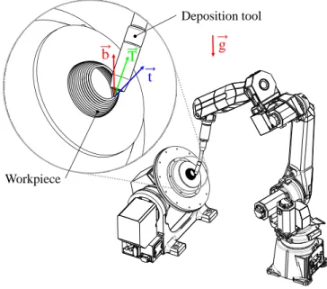
𝑏⃗ local build direction 𝑔 gravity direction
𝑡 tangent vector to the deposition path
𝑇⃗ tool axis (nozzle or torch)
2. Related work – Multi-axis deposition issues
This section presents an overview of available CAM software solutions and a summary of relevant issues related to multi-axis material deposition. For multi-axis material deposition, there are two major topics which have to be taken into account: the production set-up (including the manipulator and the deposition system) and the CAM software.
2.1. Production set up
Standard FDM machines are limited to 3-axis manipulators for material deposition. However, with only three axes, it is not possible to build up parts without support structures because the printing direction is limited to the vertical Z-direction. To achieve a multi-axis material deposition, a machine set-up with five or more axes is needed [2,3]. For large parts, one possible set-up is a standard robotised configuration, presented in Figure 1, with a 6-axis robot carrying a deposition system and a 2-axis positioner allowing to turn and tilt the workpiece. Machine setups for multi-axis additive manufacturing are available, but often the nozzles are still designed for three axis deposition strategies [3]. So, when performing multi-axis deposition strategies, the design of the deposition nozzle has to be modified to avoid collisions between the workpiece and the deposition system [4,5].
For metallic deposition, there are fewer problems of collision. Indeed, the powder nozzle or the welding torch is more distant from the workpiece, considering respectively the focal distance (10 to 15 mm) and the wire stick-out (10 to 20 mm). Nevertheless, new difficulties appear with the distortions due to the metal solidification shrinkage. Thus, some
authors proposed to build two symmetric workpieces on each side of a plate [1], requiring a platform that has to be designed accordingly. The building platforms should also be heated or cooled depending on the process used.
Fig. 1. General illustration of a multi-axis deposition device.
As multi-axis deposition strategies are recent, the design of machine components must still be improved, as well as the CAM software as detailed in the next subsection.
2.2. CAM for multi-axis deposition
Current CAM systems for additive manufacturing consist of three major steps: slicing, path planning and a post processing that is specific to the machine used [2]. During the slicing process, the geometry is separated into layers. Afterwards the toolpath is calculated for each layer. In the end, the calculated toolpath is translated into the machine specific language.
In the case of multi-axis deposition, the relative orientation between the tool (nozzle or torch) and the workpiece has to be determined all along the deposition path.
2.2.1. Global workpiece orientation
The choice of the workpiece orientation on the building platform is a key factor for the success of the build [6]. Several parameters must be taken into account for this choice:
Accessibility to the workpiece without collision between the deposition system and the platform or the part being manufactured, when they are relatively orientated to remove the need for support structures; Adhesion of the workpiece to the building platform,
with reduced distortions;
Heat transfer between the workpiece and the platform without using supports;
Characteristics of the machine axes (travel limits, accuracy, dynamics…);
The workpiece deflection under its own weight. This first step remains dependent on the user experience and could be automated in the future.
Workpiece Deposition tool
g
t
T
b
3
2.2.2. Slicing
Generally, with the help of a slicer, a component is divided into flat areas in one direction (generally Z-direction), which always have the same layer thickness. This slicing strategy, called parallel slicing, leads to a printing process strategy limited to 2.5 D well adapted to fulfilled parts. Since the layer thickness is constant, a well-known stair-step effect occurs on inclined surfaces, resulting in a higher roughness. Moreover, because of the parallel slicing, the bonding between the layers is weak and the mechanical strength in build direction could not be suitable for functional loads [4].
To overcome the stair-step effect issues, two adaptive slicing strategies are possible:
either by changing only the layer height [7], which is easy to perform with extruded polymer materials but more difficult with metal beads;
or by adapting both the slicing direction and the build direction with a multi-axis deposition device [8], which can also allow to manufacture parts without support structures.
A first approach for multi-axis slicing is based on a decomposition of the workpiece in different features according to their main direction. Then each feature is sliced individually to generate the best build direction for each of them [9,10]. To avoid collisions between the build-up part and the deposition system, specific algorithms have been developed to optimize the deposition sequence of the different layers [10,11].
For bended geometries, the slicing can be applied along the main direction of the workpiece. Numerous multi-axis slicing strategies have been proposed, such as Silhouette edges projection, Transition wall, Centroid axis extraction [12]. With these strategies, the distance between two successive layers can sometimes vary [13]. Thus, some authors proposed to straighten uneven layers by varying the layer height [8,12].
Currently, the slicing strategies are optimised for specific use cases or geometries [10] and are therefore limited for transferring the strategies to real machine setups and parts because of collisions and geometry errors [11,12].
2.2.3. Deposition strategies & Filling strategies
Once the orientation of the part has been selected and the part sliced, the deposition path can be generated. There are three different types of deposition operations which have to be differentiated for the path planning strategy, depending on the type of parts: fulfilled parts, thin-wall parts and part coatings. Fulfilled parts:
Fulfilled parts are generally manufactured using parallel slicing and 2.5D deposition strategies, as those presented in Figure 2. Most common filling strategies are zigzag, parallel or counterparallel [11,14], spiral pattern, follow pattern, helical pattern, as well as a combination of these different strategies.
Thin-wall parts:
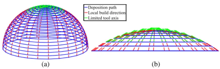
Parts with thin walls – like ribs or tubes [13] – can be considered as a particular case, because the deposition can be done line-by-line apart from layers. Continuous paths based on follow or helical pattern can be used for deposition path generation [13,14]. To avoid support use, the build direction must be calculated locally at each position, as shown in Figure 3 and explained afterwards in Section 3.
Coatings:
This operating mode can be used for multi-material overlaying, marking, repairing of worn parts and imprinting of pre-produced parts [14-16]. In order to perform a deposition on a pre-produced part, the tool axis should be positioned using the normal to the preformed surface, as illustrated in Figure 4. Coatings can be deposited using adaptive curved surface patching path patterns [15], which can be obtained from 2D paths transformed onto curved surfaces [14].
Fig. 2. Fulfilled 2.5D strategies with: (a) concentric filling; (b) contouring and hatched filling.
Fig. 3. Multi-axis strategy for thin-wall building: (a) 3D view; (b) Side zoom.
Fig. 4. Multi-axis strategies for: (a) coating using adaptive surface patch; (b) marking.
The main existing deposition strategies have been presented above. Regarding fulfilled parts, a lot of strategies already exist, whereas fewer have been developed for thin wall parts as well as coatings. First multi-axis material deposition strategies have been developed, but only for specific applications and some problems – mentioned above – are not yet overcome. Most of the actual research activities focus on the slicing and path planning, but not on the integration of additional information on the process and the machine – and their interaction with the workpiece – which is crucial for a successful deposition on experimental devices. From the state-of-the-art, the following research demand on CAD/CAM software arises:
Integration of design rules in CAD software, to obtain shapes facilitating direct deposition processes; Implementation of automated multi-axis deposition
strategies in CAM solutions, allowing to obtain continuous deposition paths for different geometries; Consideration of physical process parameter
limitations for path planning.
Deposition path Fixed build direction
(a) (b)
(a) (b)
Deposition path Local build direction Limited tool axis
(a) (b)
Deposition path Local build direction
4
3. Experimental case study based on a half-sphere
The purpose of the following case study is to illustrate the mutual influence of the kinematic setup and the path planning. This conjunction is important to study, because all current CAM workflows either do not take it into account at all or only specifically for just one single kinematic setup. Therefore, several workpieces have been manufactured on two different machine setups to identify development needs for future CAMAAM programs.
This case study adopts the half-sphere dome shape from previous studies [5,17], because it turns out useful to illustrate the specific aspects related to multi-axis deposition. The particular manufacturing challenges hereby lie in the overhang, which grows continuously, and in the closure of the centre region of the dome. Classical additive technologies would fill the dome with support structures, whereas the objective with multi-axis deposition is to get rid of such support structures.
3.1. Experimental devices
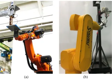
The work presented in this article originates from a collaboration initiated within the CIRP Research Affiliates network. Each of the two laboratories features a distinct robotised multi-axis deposition facility, but both with a similar configuration: a building platform moved by a robot below a fixed nozzle. The first device, shown in Figure 5(a) and located at TU Braunschweig (Germany), features a KUKA KR6 robot and an ABS granulate-feed screw-extruder system (nozzle Ø 3 mm). The second device (Figure 5(b)), located at the University of Toulon (France), involves a Stäubli RX60BL robot and a heated PLA filament extrusion system (nozzle Ø 1 mm).
The two extrusion systems are different with respect to the feeding rates, but also to their hull geometry, which may collide during the build process. In the first system, the nozzle conicity equals 93°, against 60° for the second system. This means that the angle that can be reached between the workpiece and the extruder nozzle without collision is smaller in the first system.
Fig. 5. Experimental device based at: (a) IWF institute, Germany; (b) COSMER laboratory, France.
Another difference can be spotted in Figures 5(a) and 5(b), where the different attachments of the building platforms to the
robots lead to different kinematic structures of the two devices. Indeed, with the second system, the building platform can be rotated arbitrarily around the last robot axis, while in the first, the relative orientation between the extruder nozzle and the platform is more limited.
3.2. Experimental trials
The trials consisted in building hollow half-spheres (80 mm in diameter) with both systems. The first set of tests has been performed at TU Braunschweig. Several half spheres were manufactured with different strategies. First, a 2.5D strategy was used, which caused the material to fall at the top of the sphere as reported in the literature [5,17]. Then, multi-axis strategies have been tested with two global orientations of the half-sphere. The first one, with the top of the sphere against the platform (Figure 6 (a)), did not allow to obtain a suitable shape. Better results have been obtained with the second orientation, shown in Figure 6(b), and using two separate strategies: the bottom was deposited without a tilting angle – until the red line drawn in Figure 7(a) –, then the tilt was increased up to 15°, which is the free collision limit (Figure 6(b)). However, even using a supplementary cooling system, the quality of the top of the sphere is impacted by the too high temperature of the material (Figure 7(a)).
Fig. 6. Manufacturing trials performed at IWF institute, Germany.
Fig. 7. Thinwall workpieces manufactured at: (a) IWF institute, Germany; (b) COSMER laboratory, France.
For the workpiece manufactured by COSMER, shown in Figure 7(b), the deposition strategy presented in Figure 3 was used. The path was specially generated using the iso-parametric curves of the sphere (“parallels”), which ensures a constant layer distance. The local build directions 𝑏⃗ (in red in Figure 3) are tangent to the “meridians” of the sphere and could be calculated using an automatic generation algorithm [13].
The tool axis 𝑇⃗ coincides with the build direction at the
beginning while the tilting is then limited to 60° to avoid
(a) (b)
(a) (b)
5
collisions (drawn in green in Figure 3). Thanks to this higher tilt and the faster cooling due to the smaller wall thickness, the top of the sphere is quite closed but not so clean. To achieve the best geometry, as the workpiece is axisymmetric, the deposition has been achieved using a continuous rotation of the sixth axis of the robot, which requires to specify a proper value of the rotation around the nozzle axis in the robot code.
The trials analysis leads to draw several conclusions about multi-axis deposition path planning and implementation.
The possibility to build complex shapes without supports is confirmed, even using a simple geometrical approach. Nevertheless, some difficulties are still not tackled by commercial software, like adaptive orientation to avoid collisions. Thus, a minimal framework is proposed in section 4, including all the geometrical parameters and the different calculation steps needed to plan a multi-axis deposition path.
Some actual problems, which cannot be solved by a geometrical approach, have also been observed during the tests: The quality of the top of the hollow half-sphere is not as good as the bottom. This problem seems to be due to the temperature increase when the delay between two layers deposition is too small. So deposition strategies should include cooling issues.
The relative nozzle/workpiece orientation has to be managed carefully to guarantee the quality of the workpiece and the collision avoidance.
The success of the trials is dependent on the robot configuration. Indeed, the 6 axis robots used offer six degrees of freedom (dof) while only 5 dof are needed by the extrusion process [3]. Thus, several robot configurations can be used but some of them induce practical difficulties. This subject is also relevant when a constant orientation is required by a non-coaxial deposition head (e.g. TIG welding source). Based on these observations, some evolutions of the CAM software with a systemic vision are detailed in section 4.2, in order to take into account issues related to the process and the machine/robot used.
4. Framework proposals for CAMAAM software
4.1. Minimal structure for CAMAAM software applications
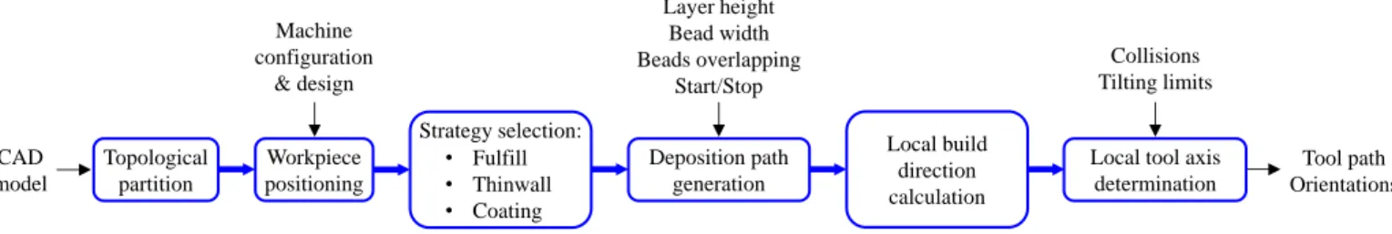
The presented state of the art and the experimental trials indicate actual weak points of CAM systems for additive manufacturing. Based on this analysis, a minimal framework for CAMAAM software is proposed in Figure 8, which concentrates on the geometrical parameters and necessary steps for a multi-axis strategy. To guaranty a good manufacturing quality and a high efficiency of the process the following six steps are proposed hereafter.
Topological partition into elementary features:
Efficient automatic feature partition into elementary deposition operations, based on the topology and the main direction of each feature.
Computer-aided global workpiece positioning:
Global workpiece orientation proposals facilitating the accessibility to each feature, avoiding collisions and minimising geometry errors, build time and warping effects. Strategy selection for each feature:
Global strategy depending on the type of work (fulfill, thinwall, coating) and the strategy set-up based on a knowledge database instead of the user experience.
Automatic deposition path generation:
Geometry adaptive deposition path with constant layer height and improved beads overlapping to increase part accuracy, and including:
- scheduling of all the elementary deposition operations together with the transitions between the several building zones;
- start and stop deposition issues, with adapted path and process parameters.
Local automatic build direction calculation:
For example by using the direction given by the nearest points of two successive layers as proposed in [13]. Local tool axis optimisation:
Tool axis determination along the path taking into account: - machine set-up limitations like building platform and
nozzle geometry to avoid local collisions;
- tilting variations allowed by the deposition process to optimise the orientation changes.
The last step can be achieved using a post-processing application or can be directly integrated into the CAM software. Further evolutions of CAM softwares are proposed in the next subsection.
4.2. Outlook: towards a systemic evolution of CAM software
The first minimal framework presented previously is a “straight” approach from the design to the additive building process only against the background of geometry. To have a successful integration of multi-axis additive manufacturing in a production route, the CAM software must become more flexible and must integrate non geometric modelling, as proposed in the diagram of Figure 9. Here the CAM tool is inter linked with additional process and machine information based on simulations (green frames) to reduce manufacturing defects. As explained in Section 3, the simulation of the machine behaviour – including geometry, kinematics and dynamics – is needed to verify that the deposition path can be really performed with a continuous deposition.
Fig. 8. Minimal framework for CAMAAM software. Workpiece positioning Strategy selection: Deposition path generation Local build direction calculation
Local tool axis determination Layer height Bead width Beads overlapping Start/Stop Collisions Tilting limits Topological partition CAD model Machine configuration & design Tool path Orientations • Fulfill • Thinwall • Coating
6 Fig. 9. Possible evolutions of CAM software.
The main important addition for future CAM software concerns thermal modelling. Indeed, the prediction of the temperature and the distortions – due to the thermal expansion and warping effects linked to the material solidification – will allow to improve material deposition and the part geometry.
From the temperature, the process parameters can be adjusted to obtain the desired bead section, either by using a database or by simulating the deposition process itself, thus allowing to predict extra information such as residual stresses. Huge deviations between the CAD model and the real part could appear during finishing because of the stress relaxation. As the geometry errors sum up over the whole process, the CAM software should be able to generate a realistic model of the part for a confrontation with the functional requirements.
The integration of design limitations of the part, like minimum wall thickness, would be also helpful. Furthermore a feedback loop between the full CAM software (including additive and post processes) and the design stage should be integrated to enable design change depending on the production to get high part quality with minimal production time and costs [18].
5. Conclusion
This article has highlighted the difficulties of additive manufacturing by multi-axis deposition and has provided proposals of frameworks for future CAMAAM software. The case study covers thermoplastic deposition processes only, but the results can also be helpful for metal deposition.
First, a minimal framework for CAMAAM software has been proposed, based on the minimal geometrical requirements needed by direct deposition processes. Then, possible evolutions of these applications have been drawn including several aspects such as:
The thermal behaviour which affects the deposition process together with the workpiece dimensions; The machine/robot configuration, whose design and
control have a major impact on the practical success, especially in the case of redundant axes;
Information about upstream and downstream production steps to obtain a fully integrated CAD/CAM chain from the design to a simulated realistic model of the workpiece.
Next research steps shall address the following issues: A method to decide the machine/robot configuration,
such that the kinematic redundancy can be used advantageously regarding the process or the part; A software architecture that allows fast evaluation of
new system configurations (kinematics, nozzles…) in the deposition path planning;
Thermal process modelling with meaningful metrics and efficient integration in CAM programs;
A feedback loop that couples the CAMAAM software and the workpiece design workflow.
References
[1] Williams SW, Martina F, Addison AC, Ding J, Pardal G, Colegrove P. Wire+arc additive manufacturing. Mater Sci Technol 2016;32/7;641-647.
[2] Ding Y, Dwivedi R, Kovacevic R. Process planning for 8-axis robotized laser-based direct metal deposition system: a case on building revolved part. Robot Comput Integr Manuf 2017;44;67-76.
[3] Dai C, Wang CC, Wu C, Lefebvre S, Fang G, Liu YJ. Support-free volume printing by multi-axis motion. ACM transactions on graphics 2018;4/1;1-13.
[4] Wulle F, Coupek D, Schäffner F, Verl A, Oberhofer F, Maier T. Workpiece and machine design in additive manufacturing for multi-axis fused deposition modeling. Proc CIRP 2017;60;229-234. [5] Shen H, Diao H, Yue S, Fu J. Fused deposition modeling five-axis
additive manufacturing: machine design, fundamental printing methods and critical process characteristics, Rapid Prototyping J 2018;24/3;548-561.
[6] Ashan N, Khoda B. AM optimization framework for part and process attributes trough geometric analysis, Additive Manuf 2016;11;85-96.
[7] Ma W, But WC, He P. Nurbs-based adaptive slicing for efficient rapid prototyping. Comput Aided Des 2004;36/13;1309-1325. [8] Zhang J, Liou F. Adaptive slicing for a multi-axis laser aided
manufacturing process. J Mech Design 2004;126;254-261. [9] Lee K, Jee H. Slicing algorithms for multi-axis 3-D metal printing
of overhangs. J Mech Sci Technol 2015;29/12;5139-5144.
[10] Ding D, Pan Z, Cuiuri D, Li H, Larkin N, van Duin S. Multi-direction slicing of STL models for robotic wire feed additive manufacturing. Proc of Annual International Solid Freeform Fabrication Symposium, 2015;1059-1069.
[11] Ren L, Sparks T, Ruan J, Liou F. Integrated process planning for a multiaxis hybrid manufacturing system. J Manuf Sci Eng 2010;132/2;021006;1-7.
[12] Ruan J, Tang L, Liou FW, Landers RG. Direct three-dimensional layer metal deposition. J Manuf Sci Eng, 2010;132/6;064502. [13] Chalvin M, Campocasso S, Baizeau T, Hugel V. Automatic multi
axis path planning for thinwall tubing through robotized wire deposition. Proc CIRP accepted.
[14] Zeng X, Yan C, Yu J, He S, Lee C. Hybrid CAM: tool path generation software for hybrid manufacturing. ICIRA 2017, Lect Notes Comput Sc 2017;10464;877-889.
[15] Ren L, Eiamsa-ard K, Ruan J, Liou F. Part repairing using a hybrid manufacturing system. Proc of ASME International Manufacturing Science and Engineering Conference, 2007;1-8. [16] Dröder K, Heyn JK, Gerbers R, Wonnenberg B, Dietrich F. Partial
additive manufacturing: experiments and prospects with regard to large series production. Proc CIRP 2016;55:122-127.
[17]Coupek D, Friedrich J, Battran D, Riedel O. Reduction of support structures and building time by optimized path planning algorithms in multi-axis additive manufacturing. Proc CIRP 2018;67;221-226. [18] Reichler A, Gerbers R, Falkenberg P, Türk E, Dietrich F, Vietor T, Dröder K. Incremental manufacturing: model-based part design and process planning for hybride manufacturing of multi-material parts, Proc CIRP accepted.
Finishing modelling Thermal modelling CAD software CAM software Deposition process database Bead section
Machine / robot simulation
Simulated temperature CAD model Design constraints Path Orientations Control constraints Allowances Rough model Residual stresses
Geometrical model of the finished part with realistic roughness Material characteristics: residual stresses, microstructure…
Process modelling Thermal distorsions Heat input • Operations planning • Path generation for each entity