HAL Id: tel-02502396
https://tel.archives-ouvertes.fr/tel-02502396
Submitted on 9 Mar 2020HAL is a multi-disciplinary open access archive for the deposit and dissemination of sci-entific research documents, whether they are pub-lished or not. The documents may come from teaching and research institutions in France or abroad, or from public or private research centers.
L’archive ouverte pluridisciplinaire HAL, est destinée au dépôt et à la diffusion de documents scientifiques de niveau recherche, publiés ou non, émanant des établissements d’enseignement et de recherche français ou étrangers, des laboratoires publics ou privés.
Dynamic modeling and characterization of magnetic
hybrid films of polyvinyl butyral/iron oxide
nanoparticles (PVB/Fe2O3) devoted to microactuators
Mayra Llamas-Hernandez
To cite this version:
Mayra Llamas-Hernandez. Dynamic modeling and characterization of magnetic hybrid films of polyvinyl butyral/iron oxide nanoparticles (PVB/Fe2O3) devoted to microactuators. Automatic. Université Bourgogne Franche-Comté; Universidad autónoma de Nuevo León, 2019. English. �NNT : 2019UBFCD034�. �tel-02502396�
THESE DE DOCTORAT DE L’ETABLISSEMENT UNIVERSITE BOURGOGNE FRANCHE-COMTE PREPAREE A L’INSTITUTE FEMTO-St
École doctorale n°37
Sciences Pour l'Ingénieur et Microtechniques (SPIM) Doctorat en automatique
Par
Mme. LLAMAS HERNANDEZ Mayra Iveth
Modélisation dynamique et caractérisation de films hybrides magnétiques de nanoparticules de polyvinylbutyral/oxyde de fer (PVB/Fe2O3) pour microactionneurs
Thèse présentée et soutenue à San Nicolás de los Garza, Nuevo León, Mexique, le 31 octobre 2019
Composition du Jury :
M. ORTIZ MENDEZ, Ubaldo Professeur à l’UANL, San Nicolas de los Garza, N.L., Mexique Président M. RAHARIJAONA, Thibaut MCF HDR à l’AMU, Marseille, France Rapporteur M. GARCÍA LOERA, Antonio Professeur à l’UANL, San Nicolas de los Garza, N.L., Mexique Rapporteur M. RAKOTONDRABE, Micky Professeur des Universités à l’ENIT, Tarbes, France Directeur de thèse Mme. LOPEZ WALLE, Beatriz MCF HDR à l’UANL, San Nicolas de los Garza, N.L., Mexique Codirecteur de thèse
Titre : Modélisation dynamique et caractérisation de films hybrides magnétiques de nanoparticules de polyvinylbutyral/oxyde de fer (PVB/Fe2O3) pour microactionneurs
Mots clés : modélisation, microactionneurs, magnétique, films, matériaux hybrides
Résumé : Les polymères hybrides peuvent être définis comme des matériaux ayant une ou plusieurs phases non organiques dispersées dans une matrice polymérique. Les films hybrides magnétiques sont généralement composés de particules magnétisables dispersées dans une matrice polymérique. Le terme film est donné en raison de leur épaisseur inférieure à 1 mm. Les films hybrides magnétiques sont un sujet intéressant de recherche dans le domaine des technologies des microactionneurs car ils offrent la possibilité d’obtenir des dispositifs magnétiques flexibles avec une manipulation sans contact.
Les modèles mathématiques décrivant les réponses dynamiques des films hybrides magnétiques soumis à des champs magnétiques externes servent de base pour l’obtention de contrôleurs du comportement.
Dans cette étude, des films hybrides magnétiques de polyvinylbutyral avec des nanoparticules d'oxyde de fer (PVB/Fe2O3) sont évalués. L’objectif général est de proposer un modèle du comportement dynamique de ces films en tant que microactionneurs en cantiléver, basé sur les propriétés physiques de ces films.
Alors, des films hybrides magnétiques ont été synthétisés à trois concentrations différentes en poids de fer (%wt Fe): 11%, 14% et 17%. Ceci permet d’obtenir trois concentrations différentes de nanoparticules d’oxyde de fer incorporées dans la matrice de PVB.
Alors, une caractérisation des propriétés physiques (mécaniques et magnétiques) des films de PVB/Fe2O3 ainsi que de leur
comportement dynamique comme
microactuateur a été réalisée.
Les résultats de la caractérisation magnétique ont montré un comportement superparamagnétique à température ambiante. Or, d'après la caractérisation mécanique, le module d'élasticité des films de PVB/Fe2O3 diminue lorsque la quantité de nanoparticules d'oxyde de fer augmente.
Le champ magnétique utilisé pour la caractérisation dynamique du comportement des microactionneurs est fourni par un électroaimant. Le courant a été appliqué selon deux modalités: mode échelon et mode oscillatoire.
Dans le mode échelon, cette caractérisation a montré un comportement amorti. Un déplacement maximal de 0,95 mm a été observé une fois atteinte la position d’équilibre ; ceci pour le microationneur contenant 17%wt Fe en appliquant un voltage de 30 V (0,87 kOe). Lors du test en mode oscillatoire, on a observé un comportement dépendant de la fréquence et la présence d’hystérésis. Une longueur de bande inférieure à 5 Hz a été estimée pour tous les microactionneurs.
La validation expérimentale du modèle a été réalisée pour le microactionneur contenant 14%wt Fe, en modifiant le voltage appliqué et les dimensions des microactionneurs. Des erreurs relatives comprises entre 1,46% et 2,66% ont été obtenues en mode échelon en comparant les déplacements expérimentaux et simulés. En mode oscillatoire, le modèle ne suit pas complètement les résultats expérimentaux, sauf pour les fréquences 0,1 Hz et 1 Hz où le déplacement maximal présente une erreur entre 4% et 7%. Cela doit être encore amélioré dans des recherches futures.
Title : Dynamic modeling and characterization of magnetic hybrid films of polyvinyl butyral/iron oxide nanoparticles (PVB/Fe2O3) devoted to microactuators
Keywords : modeling, microactuators, magnetic, films, hybrid polymers
Abstract : Polymeric hybrid materials can be defined as a material having one or more phases dispersed into a polymeric matrix. Magnetic hybrid films are a kind of polymeric hybrid materials because they are usually composed by magnetizable particles dispersed in a polymeric matrix. The term film is given due to their thickness, which is less than 1 mm.
Magnetic hybrid films are a motivating research topic for microactuator technologies because they provide the possibility to obtain flexible magnetic devices with contactless manipulation. Mathematical models describing the dynamic responses of magnetic hybrid films when subjected to magnetic fields are the basis to obtain positioning and hysteresis controllers. In this study, magnetic hybrid films of polyvinyl butyral with iron oxide nanoparticles (PVB/Fe2O3) are evaluated. The overall objective is to propose a model of the dynamic behavior of PVB/Fe2O3 films as cantilever microactuators, based on the physical properties of such films.
Magnetic hybrid films were synthesized at three different concentrations by weight of iron (%wt Fe): 11%, 14% and 17%. This allows to obtain three different concentrations of iron oxide nanoparticles embedded into the PVB matrix. Results of the magnetic characterization showed a superparamagnetic behavior at room temperature.
From mechanical characterization, it was observed a decrease in the elastic modulus of the
PVB/Fe2O3 films as the iron oxide nanoparticles content increases.
The magnetic field used for the dynamic characterization of the PVB/Fe2O3 films as cantilever microactuators was obtained by an electromagnet. The current was supplied to the electromagnet in two modalities: step mode and oscillatory mode.
Dynamic characterization showed a damped-like behavior in the step mode. A maximum settling displacement of 0.95 mm was observed for the sample with 17%wt Fe when a step voltage of 30 V (0.87 kOe) is applied. In the oscillatory mode test, a hysteretic and frequency-dependent behavior was observed. A bandwidth lower than 5 Hz was estimated for all the samples.
The experimental validation of the model was performed for the sample of 14%wt Fe with voltage and size variations. Relative errors between 1.46% and 2.66% were obtained in the step voltage mode by comparing experimental and simulated settling displacements. In the oscillatory mode, the model does not completely follow the experimental results. The smallest relative errors were obtained by comparing the values of maximum displacement between experimental and simulated results. At the frequencies of 0.1 Hz and 1 Hz, the relative errors are 4% and 7%, respectively. This must to be further improve in future researches.
Université Bourgogne Franche-Comté 32, avenue de l’Observatoire
FACULTAD DE INGENIERÍA MECÁNICA Y ELÉCTRICA
UNIVERSIDAD AUTÓNOMA DE NUEVO LEÓN FACULTAD DE INGENIERÍA MECÁNICA Y ELÉCTRICA
“Dynamic modeling and characterization of magnetic hybrid films of polyvinyl butyral/iron oxide nanoparticles (PVB/Fe2O3) devoted to microactuators”
Por
Mayra Iveth Llamas Hernández
EN OPCIÓN AL GRADO DE Doctor en ingeniería de materiales
FACULTAD DE INGENIERÍA MECÁNICA Y ELÉCTRICA
UNIVERSIDAD AUTÓNOMA DE NUEVO LEÓN FACULTAD DE INGENIERÍA MECÁNICA Y ELÉCTRICA
SUBDIRECCIÓN DE ESTUDIOS DE POSGRADO
“Dynamic modeling and characterization of magnetic hybrid films of polyvinyl butyral/iron oxide nanoparticles (PVB/Fe2O3) devoted to microactuators”
Por
Mayra Iveth Llamas Hernández
EN OPCIÓN AL GRADO DE Doctor en ingeniería de materiales
To my parents R. Llamas and G. Hernández, with their love and encouragement during my studies made this aim possible. To my husband, my favorite companion in life and in the world of science. To my son, who has become a source of motivation, inspiration and love.
AKNOWLEDGEMENTS
I would like to thank to the Consejo Nacional de Ciencia y Tecnología (CONACYT), the Universidad Autónoma de Nuevo León (UANL) and the Université Bourgogne Franche-Comté (UBFC) for the financial support provided to carry out this research.
I thank to Facultad de Ingeniería Mecánica y Eléctrica and the Femto-St Institute for having given me the opportunity to develop my Ph.D. study in their facilities.
It is a pleasure to express my deep gratitude to my mentors Dra. Beatriz Cristina López Walle and Dr. Micky Rakotondrabe for accepting this collaboration, for their patience and all their treasured guidance during the research and writing of this thesis.
I would like to express my thankfulness to Dr. Francisco Antonio García Loera, Dr. Thibaut Raharijaona and Dr. Ubaldo Ortiz Mendez for accepting to be my reviewers and for all their valuable comments to complement this thesis.
I would also like to show my gratitude to all the professors in Mexico and in France that have shared with me some of their treasured knowledge. Special mention deserves Dr. Martín Edgar Reyes Melo whose contribution has been an important part for the development of this research.
I want to give my thanks to all my friends and colleagues in Mexico and in France for the great moments together along these years.
Content
1 INTRODUCTION ... 9 1.1 CONTEXT ... 9 1.2 JUSTIFICATION ... 12 1.3 HYPOTHESIS ... 13 1.4 OBJECTIVES ... 13 1.5 THESIS ORGANIZATION ... 142 HYBRID MATERIALS, STIMULI- RESPONSIVE POLYMERS AND MICROACTUATION ... 15
2.1 INTRODUCTION ... 15
2.2 SIGNIFICANCE OF POLYMER-BASED MATERIALS IN MICROACTUATION ... 16
2.3 POLYMERIC HYBRID MATERIALS ... 18
2.4 STIMULI-RESPONSIVE POLYMERS ... 21
2.4.1 Chemical stimuli ... 23
2.4.2 Biological stimuli ... 25
2.4.3 Physical stimuli ... 26
2.5 MODELING OF MAGNETOACTIVE POLYMERS FOR THEIR CONTROL AS MICROACTUATORS... 37
2.5.1 Modeling of the magneto-mechanical properties of magnetoactive polymers 38 2.5.2 Modeling of polymer-based films as cantilever beam actuators (electroactive approach) ... 41
2.6 MAGNETIC HYBRID FILMS FOR MICROACTUATION ... 45
2.6.1 Synthesis methods to obtain magnetoactive polymeric films ... 45
2.7 CONCLUSIONS ... 49
3. SYNTHESIS AND CHARACTERIZATION OF POLYVINYL BUTYRAL WITH IRON OXIDE NANOPARTICLES (PVB/Fe2O3) FILMS ... 51
3.1 INTRODUCTION ... 51
3.2 GENERAL ASPECTS OF POLYVINYL BUTYRAL AND IRON OXIDE NANOPARTICLES ... 52
3.2.1 Polyvinyl Butyral (PVB) ... 52
3.2.2 Superparamagnetic iron oxide nanoparticles ... 53
3.3 SYNTHESIS OF THE PVB/FE2O3 FILMS ... 54
3.3.1 Used materials ... 55
3.3.2 Synthesis process ... 55
3.3.3 Obtained samples ... 57
3.4 DYNAMIC MECHANICAL ANALYSIS (DMA) ... 58
3.4.1 DMA operation principle ... 58
3.4.2 Sample preparation and measurement conditions ... 60
3.4.3 DMA results ... 61
3.5 MAGNETIC CHARACTERIZATION OF THE PVB/FE2O3 FILMS ... 65
3.5.1 Vibrating Sample Magnetometer (VSM) operation principle ... 66
3.5.2 Sample preparation and measurement conditions ... 67
3.5.3 Results of the magnetic characterization... 67
3.6 DYNAMIC CHARACTERIZATION (DISPLACEMENT UNDER MAGNETIC FIELD) ... 71
3.6.1 The experimental setup and data acquisition techniques ... 71
3.6.2 Sample preparation and measurement conditions ... 75
3.6.3 Results of the step voltage mode ... 79
3.6.4 Results of the periodic voltage mode ... 88
4 MODELING AND SIMULATION OF THE DYNAMIC DISPLACEMENTS .. 104
4.1 INTRODUCTION ... 104
4.2 THE CONFIGURATION OF THE SYSTEM ... 104
4.3 MODELING OF THE MICROACTUATOR ... 106
4.3.1 The electric circuit block ... 109
4.3.2 The electromagnet block ... 111
4.3.3 Cantilever magnetization block... 116
4.3.4 Nonlinear static displacement block ... 118
4.3.5 Linear dynamic displacement block... 127
4.3.6 Summary of equations... 130
4.4 PARAMETER IDENTIFICATION ... 133
4.4.1 Electrical circuit block ... 133
4.4.2 Magnetic field block ... 134
4.4.3 Cantilever magnetization block... 134
4.4.4 Nonlinear static displacement block ... 137
4.4.5 Linear dynamic displacement block... 137
4.5 SIMULATION OF THE MODEL ... 139
4.5.1 Step response validation ... 139
4.5.2 Oscillatory response validation ... 144
4.6 CONCLUDING REMARKS ... 153
5 CONCLUSION AND PERSPECTIVES ... 155
6 Appendix 1 ... 174
7 Appendix 2 ... 177
8 Appendix 3 ... 180
9 Appendix 4 ... 187
1
List of figures
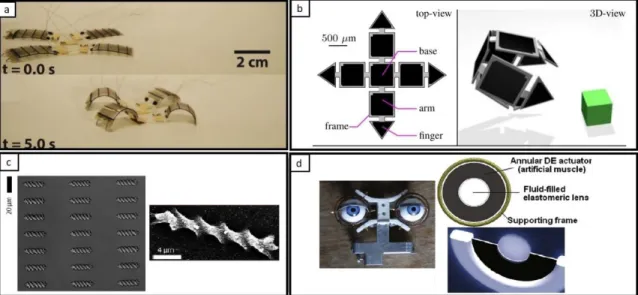
Figure 1.1. Schematic representation of a cantilever beam microactuator. ... 13 Figure 2.1. Examples of the applications of microactuators. (a) Four-legged small size robot. Legs are made of a polymer that responds to electric stimulus (dielectric polymer) (Adapted from [28]). (b) Magnetic microgripper for micromanipulation based on a polymer with embedded magnetic nanoparticles. This polymer is activated by magnetic fields (adapted from [29]). (c) Biodegradable magnetically driven micro-swimmer for drug delivery. It is made of a polymeric matrix with iron oxide nanoparticles (adapted from [30]). (d) Mechanisms for eyes muscles emulation using dielectric (DE) polymers (adapted from [31][32])... 16 Figure 2.2. Comparison between a conventional material and a polymer-based material considering their actuation (Adapted from [33]). ... 17 Figure 2.3. Schematic examples of the different approaches to obtain hybrid materials: (a) the building block approach, (b) the in-situ approach. ... 20 Figure 2.4. Popular applications of polymeric hybrid materials and their relationship with stimuli-responsive polymers. ... 20 Figure 2.5. Classification of the stimuli-responsive polymers according to the stimuli they can respond... 22 Figure 2.6. General methods to obtain stimuli-responsive polymers and their relationship with polymeric hybrid materials. ... 22 Figure 2.7. Representation of a pH-responsive polymer. It is possible to see the transition from a folded state to unfolded state due to changes in pH and cations formation. ... 24 Figure 2.8. Representation of the actuation of an enzyme-responsive polymer. ... 25 Figure 2.9. Phase diagram showing UCST and LCST behavior (temperature versus polymer weight fraction). ... 27 Figure 2.10. Actuation mechanism of the thermally induced shape memory effect in SMP. ... 28 Figure 2.11. Schematic representation of a photo-responsive polymer actuation in drug delivery. ... 29
2 Figure 2.12. Classification of magnetoactive polymers according to the used polymeric
matrix (adapted from [106]). ... 32
Figure 2.13. Arrangement of magnetic moments in (a) ferromagnetic materials and (b) ferrimagnetic materials... 32
Figure 2.14. (a) Representation of the domains inside ferromagnetic and ferrimagnetic materials. When they are under an external magnetic field H, they start to move to the direction of the field (b) in order to be parallel to it like in (c). ... 33
Figure 2.15. Representative hysteretic behavior of ferromagnetic and ferrimagnetic materials. ... 34
Figure 2.16. Representation of magnetic moments in superparamagnetic nanoparticles. ... 35
Figure 2.17. Magnetization curve of a superparamagnetic material. ... 36
Figure 2.18. Scanning Electron Microscope (SEM) images of magnetic particles in a polymeric elastomer: (left) without external magnetic field, (right) particles aligned after applying a magnetic field, adapted from [123]. ... 40
Figure 2.19. (Left) Schematic structure of the PPy trilayer actuator. (Right) Schematic beam model with the load distribution, adapted from [130]. ... 43
Figure 2.20. Assignment for rigid finite elements and spring-damper elements, adapted from [127]. ... 44
Figure 2.21. Different classifications where magnetoactive polymeric films can be found. ... 45
Figure 2.22. Schematic representation of the film casting process. ... 46
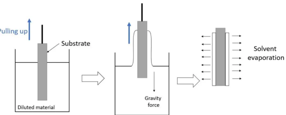
Figure 2.23. Steps of the dip-coating technique to obtain polymeric films. ... 47
Figure 2.24. Steps of the spin-coating technique to obtain polymeric films... 48
Figure 3.1. Chemical structure of the PVB. ... 52
Figure 3.2. Schema of the synthesis process of the PVB/Fe2O3 films. ... 56
Figure 3.3. Stress response of different kind of materials: (a) applied periodic strain stimulus, (b) pure elastic response, (c) pure viscous response and (d) viscoelastic response. ... 59
Figure 3.4. Schematic of a DMA in tension mode. ... 60
Figure 3.5. DMA results at frequency strains of 0.1 Hz and 1 Hz for: (a) pristine PVB, (b) PVB/Fe2O3_11%wt Fe, (c) PVB/Fe2O3_14%wt Fe and (d) PVB/Fe2O3_17%wt Fe... 62
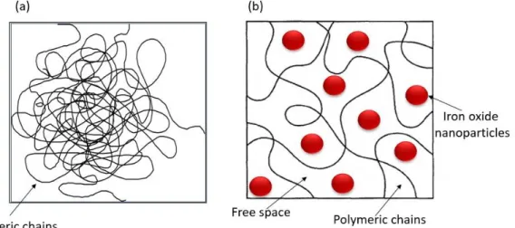
3 Figure 3.6. Schematic representation of the polymeric chains: (a) entangled polymeric chains and (b) plasticizer effect of iron oxide nanoparticles on the polymeric chains. ... 63 Figure 3.7. Agglomerates of iron oxide nanoparticles into de PVB matrix. ... 64 Figure 3.8. Schema of a magnetic sample magnetometer functioning. ... 66 Figure 3.9. Encapsulation of the samples for magnetic measurements. ... 67 Figure 3.10. Magnetization curves of the PVB/Fe2O3 films measured at room temperature (300 K). ... 68 Figure 3.11. Zoomed view around the zero-magnetization point of the magnetization curves for the samples: (a) PVB/Fe2O3_11%wt Fe, (b) PVB/Fe2O3_14%wt Fe and (c) PVB/Fe2O3_17%wt Fe. ... 69 Figure 3.12. Schematic representation of the actuation system. ... 71 Figure 3.13. Schema of the experimental setup and the flow process to acquire the displacement values of the PVB/Fe2O3 films under external magnetic fields. ... 73 Figure 3.14. Laboratory workspace for the displacement measurements: (a) experimental setup, (b) a close-up view of the electromagnet and the film, (c) the laser sensor conditioner and (d) the controller board for the communications with the PC. ... 74 Figure 3.15. Position of the gaussmeter probe to take measurements of the magnetic field generated by the electromagnet at 2 mm of distance. ... 74 Figure 3.16. Two different modalities of input voltage: (a) the step voltage mode and .. 77 Figure 3.17. Design of experiments for the dynamic characterization. Experimental conditions for: (a) step voltage mode and (b) periodic voltage mode... 78 Figure 3.18. Characteristic underdamped response for a step voltage input. ... 79 Figure 3.19. Responses of the microactuators at three different iron oxide nanoparticles concentrations: (a) PVB/Fe2O3_17%wt Fe, (b) PVB/Fe2O3_14%wt Fe and (c) PVB/Fe2O3_11%wt Fe. ... 81 Figure 3.20. Schematic representation of the iron oxide nanoparticles in the PVB matrix of the microactuators: (a) without magnetic field and (b) when an external uniform magnetic field H is applied. ... 82 Figure 3.21. Responses of the PVB/Fe2O3_14%wt Fe microactuator at two different step voltage inputs: (a) 30 V and (b) 15 V. ... 85
4 Figure 3.22. Responses of the PVB/Fe2O3_14%wt Fe microactuator with different dimensions. (a) Size 1: 15 mm in length, 2 mm in width, 0.018 mm in thickness. (b) Size 2: 15 mm in length, 4 mm in width, 0.018 mm in thickness. ... 87 Figure 3.23. Recorded data in the periodic mode tests: (a) periodic voltage input, (b) oscillatory response (displacement) of the microactuator, (c) hysteresis loop of the displacement in function of the input voltage. ... 89 Figure 3.24. Response of a dielectric elastomer: (a) the transition and stable regions of the oscillatory displacement, (b) the effects of the transition region in the hysteresis loops [181]. ... 90 Figure 3.25. Experimental responses of the PVB/Fe2O3 microactuators at 0.1 Hz, 1 Hz, 5 Hz and 10 Hz: (a) PVB/Fe2O3_17%wt Fe, (b) PVB/Fe2O3_14%wt Fe and (c) PVB/Fe2O3_11%wt Fe. ... 92 Figure 3.26. 2D simulation of the cantilever beam exposed to different magnetic field gradients. ... 93 Figure 3.27. Oscillatory input voltage and harmonic displacement for the microactuators of the samples: (a) PVB/Fe2O3_17%wt Fe, (b) PVB/Fe2O3_14%wt Fe and (c) PVB/Fe2O3_11%wt Fe. ... 94 Figure 3.28. Experimental responses of the PVB/Fe2O3 microactuators at 20 Hz, 30 Hz, 40 Hz and 50 Hz: (a) PVB/Fe2O3_17%wt Fe, (b) PVB/Fe2O3_14%wt Fe and (c) PVB/Fe2O3_11%wt Fe. ... 96 Figure 3.29. Experimental responses of the PVB/Fe2O3_14%wt Fe microactuator at 0.1 Hz, 1 Hz, 5 Hz and 10 Hz, applying voltages of: (a) 0-30 V, (b) 0-15 V. ... 98 Figure 3.30. Oscillatory input voltage and harmonic displacement of the PVB/Fe2O3_14%wt Fe microactuator with voltages of: (a) 0-30 V and (b) 0-15 V. ... 98 Figure 3.31. Experimental responses of the PVB/Fe2O3_14%wt Fe microactuator at 20 Hz, 30 Hz, 40 Hz and 50 Hz, with voltages of: (a) 0-30 V and (b) 0-15 V. ... 99 Figure 3.32. Experimental responses of the PVB/Fe2O3_14%wt Fe microactuators at 0.1 Hz, 1 Hz, 5 Hz and 10 Hz; voltage of 0-30 V and dimensions (length, width, thickness) of: (a) 15 mm, 2 mm, 0.018 mm (size 1) and (b) 15 mm, 4 mm, 0.018 mm (size 2). ... 100 Figure 3.33. Oscillatory input voltage and harmonic displacement of the microactuators with dimensions (length, width, thickness) of: (a) 15 mm, 2 mm, 0.018 mm (size 1) and (b) 15 mm, 4 mm, 0.018 mm (size 2). ... 101
5 Figure 3.34. Experimental responses of the PVB/Fe2O3_14%wt Fe microactuator at 20 Hz, 30 Hz, 40 Hz and 50 Hz; voltage of 0-30 V and dimensions (length, width, thickness)
of: (a) 15 mm, 2 mm, 0.018 mm (size 1), (b) 15 mm, 4 mm, 0.018 mm (size 2). ... 102
Figure 4.1. Representation of the PVB/Fe2O3 cantilever microactuator. ... 105
Figure 4.2. Block representation of the whole actuation process. ... 106
Figure 4.3. Block diagram of the model including each sub-block. ... 106
Figure 4.4. Plane sections remain plane before and after deformation. ... 109
Figure 4.5. Representation of the electromagnet as a series RL circuit. ... 109
Figure 4.6. Magnetic field contribution of a current loop at a point P on the z-axis. .... 112
Figure 4.7. Schematic representation of a solenoid. ... 113
Figure 4.8. Schematic representation of a multilayer solenoid. ... 114
Figure 4.9. Schema of the large deformation (displacement) of the microactuators. .... 119
Figure 4.10. Algorithm to estimate the value of ∆. ... 125
Figure 4.11. Example of a moment diagram for a cantilever beam with an applied force at its free end. ... 127
Figure 4.12. Relation between 𝛿𝐷𝑑𝑦𝑛𝑎𝑚𝑖𝑐 and 𝛿𝐷𝑠𝑡𝑎𝑡𝑖𝑐. ... 128
Figure 4.13. Relation between 𝛿𝐷𝑑𝑦𝑛𝑎𝑚𝑖𝑐 and 𝛿𝐷𝑠𝑡𝑎𝑡𝑖𝑐 incorporating the term 𝑔 (gain). ... 128
Figure 4.14. Example of test results of magnetization (M) versus magnetic field strength (H). The zoomed area shows the approximately linear behavior of this kind of responses at low magnetic fields. ... 136
Figure 4.15. Conditions to evaluate by the model in the step mode. ... 140
Figure 4.16. Example of the simulated responses for each block of the overall model: (a) applied step voltage of 30 V, (b) current flowing through the electromagnet due to the applied voltage, (c) magnetic field dependent of the current, (d) magnetic force in function of the magnetic field, (e) static displacement of the microactuator free end, and (f) dynamic displacement of the microactuator free end. ... 141
Figure 4.17. Validation of the model for: (a) current and (b) magnetic field, by applying a step voltage of 30 V. ... 142 Figure 4.18 Comparison between simulated and experimental dynamic displacements for the microactuator of the sample PVB/Fe2O3_14%wt Fe tested at the following conditions:
6 (a) 30 V of step and size 1, (b) 15 V of step and size 1, and (d) 30 V of step and size 2.
... 144
Figure 4.19. Conditions to evaluate by the model in the periodic voltage mode. ... 145
Figure 4.20. Comparison between simulated and experimental dynamic displacements for the PVB/Fe2O3_14%wt Fe microactuator, tested in the oscillatory voltage mode. The test was carried out for the microactuator of size 1 by applying a voltage of 0-30 V and frequency of: (a) 0.1 Hz, (b) 1 Hz and (c) 5 Hz. ... 147
Figure 4.21. Examples of different kind of magnetic force distributions along the cantilever microactuator. ... 149
Figure 4.22. Comparison between simulated and experimental dynamic displacements for the microactuator of the sample PVB/Fe2O3_14%wt Fe, tested in the oscillatory voltage mode. The tests were carried out for the microactuator of size 1 by applying a sine voltage of 0-15 V and frequencies of: (a) 0.1 Hz, (b) 1 Hz and (c) 5 Hz. ... 150
Figure 4.23. Comparison between simulated and experimental dynamic displacements for the microactuator of the sample PVB/Fe2O3_14%wt Fe, tested in the oscillatory voltage mode. The tests were carried out for the microactuator of size 2 by applying an amplitude of 0-30 V and frequencies of: (a) 0.1 Hz, (b) 1 Hz and (c) 5 Hz. ... 151
Figure 4.24. Estimated transfer function’s bode diagram. ... 152
Appendix figures
Figure A3. 1. Last block of the overall block-structured model representing the linear dynamics and proposed in chapter 4. ... 180Figure A3. 2. Interface of the System Identification Toolbox of MATLAB. ... 180
Figure A3. 3. Import data in the time domain. ... 181
Figure A3. 4. Declaration of input, output, starting time and sampling time. ... 182
Figure A3. 5. Input and output behavior of the dynamic system. The input (u1) corresponds to the static displacement, while the output (y1) is the experimental dynamic displacement. ... 182
Figure A3. 6. The model was estimated as a polynomial model. ... 183
Figure A3. 7. Different polynomial model structures. ... 184
7
Figure A3. 9. Agreement between model and experimental responses. ... 185
Figure A3. 10. The model is sent to the workspace of MATLAB. ... 185
Figure A3. 11. Discrete transfer function from the selected polynomial model. ... 186
Figure A3. 12. Obtained continuous time transfer function... 186
Figure A4. 1. Interpretation of ARX models. Dynamic system with input 𝑢(𝑡), error 𝑒(𝑡) and output 𝑦𝑡. ... 187
8
List of tables
Table 2.1. Classification of EAPs and their characteristic examples. ... 30 Table 2.2. Modeling of the magneto-mechanical properties of magnetoactive polymers at different scales. ... 38 Table 3.1. Raw materials for the synthesis of PVB/Fe2O3 films. ... 55 Table 3.2. PVB and FeCl2 ∙4H2O content for the three different samples. ... 57 Table 3.3. Values of elastic modulus (E’) and glass transition temperature (Tg), obtained at 0.1 Hz and 1 Hz, for all the samples. ... 62 Table 3.4. Magnetic parameters for the magnetization curves for the three magnetic films concentrations. ... 70 Table 3.5. Magnetic field strength and magnetic flux density in function of current and applied voltage. All these values were taken at 2 mm from the central axis of the electromagnet. ... 75 Table 3.6. Maximum displacement and settling displacement values for the three microactuators with different iron oxide nanoparticles content. ... 83 Table 3.7. Peak time and settling time values for the three microactuators with different iron oxide nanoparticles content. ... 84 Table 3.8. Maximum displacement and settling displacement values for the PVB/Fe2O3_14%wt Fe microactuator at 30 V and 15 V of step voltage. ... 86 Table 3.9. Peak time and settling time values for the PVB/Fe2O3_14%wt Fe microactuator at 30 V and 15 V of step voltage. ... 86 Table 3.10. Maximum displacement and settling displacement values for the PVB/Fe2O3_14%wt Fe microactuator of size 1 and size 2. ... 87 Table 3.11. Peak time and settling time values for the PVB/Fe2O3_14%wt Fe microactuator of size 1 and size 2. ... 88 Table 4.1. Comparison between experimental and simulated settling displacements. .. 144 Table 4.2. Comparison between experimental and simulated maximum displacements. ... 152
9
CHAPTER 1
1
INTRODUCTION
This thesis was accomplished in a dual-degree modality between the consolidated group of Synthesis and Characterization of Materials ꟷFacultad de Ingeniería Mecánica y Eléctrica (FIME), Universidad Autónoma de Nuevo León (UANL), México, and the research group of Methodologies for Automatic Control and for Design of Mechatronic Systems (MACS), department of Automatic Control and Micro-Mechatronic Systems ꟷ FEMTO-ST institute, Université Bourgogne Franche-Comté (UBFC), France.
1.1 CONTEXT
Research and development of polymeric hybrid materials have been widely discussed in recent times. A polymeric hybrid material is considered as a polymeric matrix (organic phase) having one or more inorganic phases dispersed inside it [1]. The synthesis of these materials allows to exploit the exceptional properties of polymers (toughness, good elongation, processability, lightweight and low cost) and they can be combined with the properties of other materials. This combination of properties makes polymeric hybrid materials suitable for specific applications.
Some polymeric hybrid materials have the ability to change their properties in response to an external stimulus and they can return to their original state on termination of the stimulus; these materials are called stimuli-responsive polymers [2]. There are different
10 stimuli at which these materials could respond, such as changes in pH, temperature, electric or magnetic fields, among others. Stimuli-responsive polymers that respond to external magnetic fields are called magnetoactive polymers and they are usually formed by magnetic particles dispersed within a polymeric matrix [3].
Magnetoactive polymers have very promising applications as microactuators. An actuator could be considered as a device that transforms energy from an external source into mechanical energy in a controllable manner [4]. The current trend suggests that the miniaturization of these devices should be implemented in applications such as magnetic micromanipulation, biomedical or biomimetics [5].
The use of magnetoactive polymers as microactuators permits to obtain devices with the following advantages [5]:
ꟷ Flexibility
ꟷ Lightweight and low-density ꟷ Relative low cost of processing ꟷ Optical transparency
ꟷ Remote and wireless control
ꟷ Operation in many different media including air, vacuum, conducting and non-conducting liquids.
A number of researches have been published on magnetic microactuators technology using magnetoactive polymers, for example as micropumps in peristaltic devices which can aid the blood circulation by venous contraction [6], microactuators for microinvasive surgery and handling cells [7], microgrippers of manipulating microscale objects [8], for drug delivery applications which enable long-term and targeted drug release [9], microvalves for microfluidic applications [10] or even to emulate the movement of natural muscles due to its high flexibility [11].
Despite the significant applications of microactuators using magnetoactive polymers, there are many interrogations to fully understand and exploit these materials. The prediction of the constitutive nonlinear dynamic responses of magnetoactive polymers when subjected to magnetic fields poses a tremendous challenge [12]. Moreover, magnetoactive polymers shows frequency dependence and hysteretic behavior that must
11 be also identified [13]. The understanding of all these concepts is necessary due to the high positioning accuracy and precision required for the expected applications [14]. Mathematical models describing the dynamic responses of magnetoactive polymers are the basis to obtain positioning and hysteresis control of these materials. Mathematical models can be based on physical principles involving the properties of the material [15]. This approach allows to visualize the optimal magnetic and mechanical properties configuration from a materials science point of view. In consequence, it is necessary to make a previous analysis of the physical properties of the magnetoactive polymers and their influence on the dynamic response in order to propose an accurate model.
Several models of the dynamic response of magnetoactive polymers based on physical principles have been previously reported [16][17][18][19]. However, many questions are still to be answered. Moreover, there is not a general solution for these models because the dynamic response is dependent on each particular case. Therefore, the modeling of the dynamic response of magnetoactive polymers must be performed by considering the properties of the specific polymeric matrix, the kind of magnetic particles and the coupled magnetic-mechanical properties obtained by the combination of both elements [12][20]. The magnetoactive material used in this thesis was selected following the research line of the group Synthesis and Characterization of Materials, FIME, UANL. In 2013, magnetic hybrid films of polyvinyl butyral (PVB) with iron oxide nanoparticles (Fe2O3) were
synthesized and characterized [21]. The term film was given due to their thickness, which is less than 1 mm (~ 18 m). These magnetic hybrid films behave as magnetoactive polymers and their potential for applications as microactuators was observed. Subsequently, other researches were performed to deepen the understanding of the physical properties of these magnetic hybrid films, specially dielectric and mechanical properties [22][23]. Further, the behavior of a cantilever microactuator of copper with a section of magnetic hybrid film of PVB/Fe2O3 added to its free end was evaluated [24].
Experiments were conducted by applying different magnetic fields and measuring the displacement of the free end. A mathematical model for the measured responses was proposed. Results showed that PVB/Fe2O3 films attached to the free end of the copper
12 cantilever promotes a magnetic response, however, copper reduces flexibility to the microactuator. Based on these results, the possibility of exploring the PVB/Fe2O3 films as
cantilever microactuators without any other added element was posed. Moreover, developing a control of this kind of microactuator would be advantageous to exploit potential applications where precise positioning is required.
1.2 JUSTIFICATION
As seen in the context described in the last section, there is a great potential to use magnetoactive polymers as microactuators. However, there are still many challenges to be assessed to understand and predict the behavior of these materials when they are subjected to external magnetic fields. The understanding and prediction of these materials is necessary to obtain the positioning and hysteresis control that the application as microactuator demands.
The understanding of the behavior of these materials can be obtained by the analysis of both their physical properties (magnetic-mechanical) and their influence on the behavior when the material is under magnetic fields. The prediction of the behavior of these materials can be estimated by mathematical models. Mathematical models with a physical approach involve the physical properties of magnetoactive polymers [12][20]. By giving a physical approach, it is possible to visualize the optimal properties configuration from materials science point of view. This may permit to modify the synthesis processes and methods in order to achieve the required properties.
Based on the previously mentioned, this study is focused on the modeling of the dynamic response of microactuators composed by magnetic hybrid films of polyvinyl butyral (PVB) with iron oxide nanoparticles (Fe2O3). These films behave as a magnetoactive
polymer and their potential as microactuator was evaluated in cantilever beam configuration, according to Figure 1.1.
13
Figure 1.1. Schematic representation of a cantilever beam microactuator .
The dual-degree modality of this thesis was stablished to take advantage of the experience of each institution in their research fields: on the one hand, to continue with the well-defined research line on magnetoactive polymers as well as with the experience on characterization and the relation structure-properties of materials (FIME, UANL, México); on the other hand, the experience on microdevices, dynamic characterization and modeling (FEMTO-ST, UBFC, France). It is also expected that the model works as a starting point to stablish a control of the behavior of the material for its application as microactuator.
Considering all above, the hypothesis and objectives of the research project were stablished, and they are described in next sections.
1.3 HYPOTHESIS
The dynamic behavior of PVB/Fe2O3 films as microactuators can be predicted by a model that relates the physical properties of the films (magnetic and mechanical) with their dynamic response (displacement) when subjected to external magnetic stimulus.
1.4 OBJECTIVES
The main objective of the project is to model the dynamic behavior of a polymer-based
hybrid films consisting of a polymer matrix of polyvinyl butyral (PVB) with iron oxide
14 To achieve the main objective, four goals are proposed:
1 To perform the characterization of the physical (magnetic and mechanical) properties of the films.
2 To carry out experimental studies of the response (displacement) produced by a magnetic field in PVB/Fe2O3 films as cantilever microactuators.
3 To relate the properties (mechanical-magnetic) of the PVB/Fe2O3 films with the displacement of the material as a function of an external magnetic field.
4 To get a dynamic model for the behavior of the film and to validate it.
1.5 THESIS ORGANIZATION
This thesis is divided in five chapters:
The first chapter corresponds to the context and justification of the problematic, as well as the hypothesis and objectives of the thesis.
The second chapter deals in detail with the different kinds of stimuli responsive polymers and the significance to apply this kind of polymers as microactuators, given more attention to polymers that respond to magnetic fields (magnetoactive polymers). The importance to understand and predict the behavior of magnetoactive polymers is also explained. Moreover, a survey on the modeling of microactuators is presented.
The third chapter explains thoroughly the synthesis process to obtain the magnetic hybrid films of PVB/Fe2O3. The methods followed to perform the characterization of the physical properties and the dynamic behavior under static and oscillatory magnetic fields are also described. In addition, the results of the obtained results are discussed in this chapter. The fourth chapter deals with the followed method to obtain the model describing the dynamic behavior of PVB/Fe2O3 films as cantilever microactuators. The validation of the model is also performed in this section.
The fifth chapter corresponds to the general conclusions and future perspectives according to the results and analysis of this research.
15
CHAPTER 2
2
HYBRID MATERIALS, STIMULI-
RESPONSIVE POLYMERS AND
MICROACTUATION
2.1 INTRODUCTION
Polymeric hybrid materials and stimuli-responsive polymers are considered as good candidates for microactuators. However, these materials remain under study for two main reasons: the physical properties must be well understood to stablish their influence on the response and a control of the response is required to obtain an optimal performance. It is considered that a good control design starts from predictive models of the responses. Thus, the modeling of these polymers is also an important research subject. In this chapter, the significance to use polymer-based materials as microactuators is presented in section 2.2. The concept and generalities of polymeric hybrid materials and stimuli-responsive polymers are exposed in sections 2.3 and 2.4, respectively. A special emphasis is given to polymers that respond to magnetic stimuli (magnetoactive polymers) which are the target of this thesis. The importance to understand and predict the behavior of magnetoactive polymers by modeling is explained in section 2.5. Finally, section 2.6 shows the
16 advantages to use magnetoactive polymeric films on microactuation along with their limitations.
2.2 SIGNIFICANCE OF POLYMER-BASED MATERIALS IN MICROACTUATION
Actuators are fundamental components of many industrial and natural processes. An actuator is, basically, a converter that transforms any kind of energy source into a mechanical energy [4]. Examples of actuators are motors, valves, relays, pumps, grippers, and so on. Recent trends suggest the miniaturization of actuators for the development of smaller systems, especially for industrial or medical applications.
Microactuators are actuators that can produce small force and motion at microscales (from 1 millimeter upper to 0.1 micrometer lower limits) [25][26]. They are used for applications like small-size robots or micromanipulation. In other cases, when microactuators are made of biodegradable or biocompatible materials, they can be used in applications such as artificial muscles or microrobots for drug delivery [27]. Figure 2.1 shows some examples of the mentioned applications.
Figure 2.1. Examples of the applications of microactuators . (a) Four-legged small size robot. Legs are made of a polymer that responds to electric stimulus (dielectr ic polymer) (Adapted from [28]). (b) Magnetic microgripper for micromanipulation based on a polymer with embedded magnetic nanoparticles. This polymer is activated by magnetic fields (adapted from [29]). (c) Biodegradable magnetically driv en micro -s wimmer for drug
17
delivery. It is made of a polymeric matrix with iron oxide nanoparticles (adapted f rom [30]). (d) Mechanisms for eyes muscles emulation using dielectric (DE) polymers (adapted from [31][32]).
We can observe from all the examples in Figure 2.1 that actuation at micrometric scales requires, among others, the ability to respond to certain stimulus, flexibility and lightweight. In this way, conventional materials used for actuating tasks (e.g. metals and their alloys, or ceramics) may be replaced by polymer-based materials in order to obtain more efficient actuation at such scales. Otherwise, the rigidity of conventional materials causes the need of articulations driven by motors or pneumatic systems. In consequence, the systems become bulky and several subcomponents such as screws, nuts or gearbox at very small scales would be needed. Moreover, the several joints of subcomponents may produce friction of clearance, which makes difficult to obtain accurate positioning or fast response times [33]. Figure 2.2 shows schematically the difference to use a conventional material and a polymer-based material for a polyarticulated arm. It is shown in figure that the use of polymer-based materials avoids the need of additional components to perform the same actuation.
Figure 2.2. Comparison between a conventional material and a polymer -based material considering their actuation (Ada pted from [33]).
There are many efforts focused on the development of polymer-based materials to be used as microactuators. Polymeric hybrid materials and stimuli responsive polymers are considered as good candidates for these applications. They correspond to two different
18 research areas. However, it is possible to obtain new materials by combining characteristics and properties of both. Next sections of this chapter give a frame of the efforts focused on these topics.
2.3 POLYMERIC HYBRID MATERIALS
Polymeric hybrid materials are materials composed of an organic matrix (a polymer) with one or more inorganic components [1]. The importance of these materials lies in the exceptional properties that can be achieved from the synergy of the properties of each individual component.
The final properties of hybrid materials depend mostly on the interface interactions between organic and inorganic components. Interface interactions can be weak, for example van der Waals or hydrogen bonding. Weak interactions are preferred when a dynamic behavior is needed, for example when some mobility of a component is necessary for the final application [34]. However, interactions may be also very strong, such as ionic or covalent bonding. Strong interactions avoid agglomerations or phase separation between components and they markedly influence the final mechanical, electrical or thermal properties.
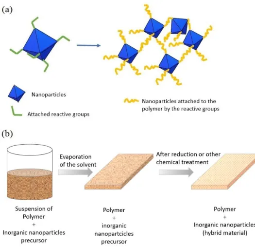
The inorganic components added into the polymeric matrix to form a hybrid material commonly show a morphology of particles, whiskers or fibers. Basically, there are two different approaches to obtain a hybrid material. These two approaches are: the building block approach and the in-situ formation of inorganic components [35].
In the building block approach, the inorganic building blocks completely conserve (or at least partially) their molecular integrity throughout the formation of the hybrid material. One example of this approach is the addition of nanoparticles with attached reactive groups. These reactive groups enhance the interactions between inorganic building blocks and the polymeric matrix. Figure 2.3(a) shows the schematic representation of this approach.
19 In the in-situ formation of inorganic components approach, the hybrid material is obtained by the chemical transformation of a precursor material. In this case, the properties of the final material are totally different from the original precursor. The main advantage of this approach is the use of low temperatures and pressure to process some ceramics (e.g. oxides) [36]. The most common way for the in-situ formation is the synthesis by the sol-gel method. This method starts from a colloidal suspension of a solid material called sol, which can be the precursor of the inorganic component with a polymer (or monomer). Then, a precursor hybrid material is formed (called gel) as the product of some chemical reactions occurring in the suspension. The final hybrid material is obtained after solvent evaporation [37] and, in some cases, after post-chemical treatments. One example of the
in-situ formation of nanoparticles into a polymer is schematically shown in Figure 2.3(b).
Polymeric hybrid materials could be applied in bulk, as films, or shaped in any form [34]. Polymeric hybrid materials are used as sensors[38][39], microactuators [40] [41][42], mechanical reinforcements for building, automotive or aircraft fields [43][44][45][46], absorbent materials to remove pollutants in water or other media [47][48], scaffolds for tissue engineering [49], among many others.
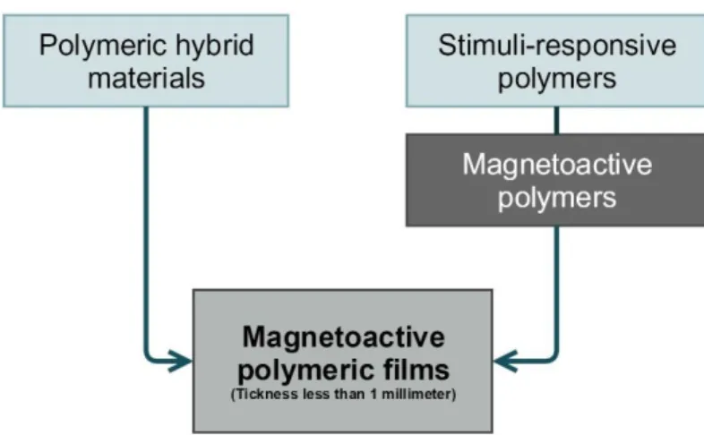
Mostly, polymeric hybrid materials used for sensors and microactuators are obtained by the incorporation of stimuli-sensitive inorganic components into the polymeric matrix. This results in a special kind of polymeric hybrid material called stimuli-responsive polymer. Figure 2.4 shows some relevant applications of polymeric hybrid materials and their relationship with the stimuli-responsive polymers. The route concerning this thesis is highlighted in green.
It is important to clarify that stimuli-responsive polymers correspond to another research field and they could be obtained by other methods. Generalities concerning stimuli-responsive polymers are described in section 2.4
20
Figure 2.3. Schematic examples of the different approaches to obtain hybrid materials : (a) the building block approach , (b) the in-situ approach.
Figure 2.4. Popular applications of polymeric hybrid materials and their relationship with sti muli -responsive polymers.
21 2.4 STIMULI-RESPONSIVE POLYMERS
There is a wide research line focused on stimuli-responsive polymers. This kind of polymers can be also found in literature as smart polymers, active polymers or soft active materials [50].
Stimuli-responsive polymers have the ability to change some chemical or physical aspects such as their shape, solubility, permeability, mechanical/optical/electrical or magnetic properties when subjected to a variation of environmental conditions. These variations can be: changes in pH, temperature, light, magnetic or electric field, and so forth [51]. The change of properties of a stimuli-responsive polymer could be reversible: it returns to its initial state when the external stimulus is removed.
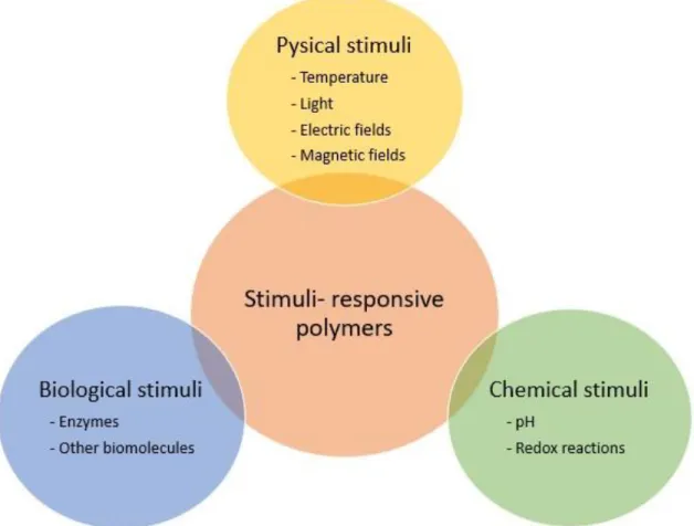
Stimuli at which polymers respond can be classified into three categories: biological, chemical and physical stimuli [52][53]. Biological stimuli correspond to changes of some biological substances, such as enzymes, glucose or other metabolites. Chemical stimuli are related to changes in pH and some ionic or redox reactions. Physical stimuli could be variations in temperature, light, electric or magnetic fields. These three categories are summarized in the diagram of Figure 2.5. Moreover, there are some polymers with the ability to respond to more than one stimulus.
Synthesis of stimuli-responsive polymers can be generally achieved by two methods. One method is conducted by the addition of stimuli-sensitive functional groups along the polymer backbone [50][54]. The second method involves the incorporation of some stimuli-sensitive inorganic components within the polymeric matrix, thus obtaining polymeric hybrid materials [1][55][56][57]. Figure 2.6 shows the two methods to obtain stimuli-responsive polymers and their relationship with polymeric hybrid materials. The route concerning this thesis is colored in green.
22
Figure 2.5. Classification of the stimuli -responsive polymers according to the stimuli they can respond.
Figure 2.6. General methods to obtain stimuli -resp onsive polymers and their relationship with polymeric hybrid materials.
23 A brief description of the activation mechanism for the different stimuli-responsive polymers is presented in next sections. Representative examples of applications of this kind of polymers are also given. More emphasis will be addressed to the polymers that respond to magnetic fields (magnetoactive polymers) which are the polymers of main interest for this research.
2.4.1 Chemical stimuli
2.4.1.1 pH-responsive polymers
pH-responsive polymers accept or release protons in function of pH changes. They have acidic or basic groups in their structure linked to the polymer backbone such as carboxy or amino groups [58]. As pH-responsive polymers work in aqueous media, they can be defined as polyelectrolytes. A polyelectrolyte is a macromolecule that can dissociate to give polymeric ions when dissolved in water or other ionizing solvents [59]. A change of pH promotes the ionization of the acidic or basic groups and generates anions or cations. These anions or cations cause an extension of the polymeric chains due to electrostatic repulsion [60]. Figure 2.7 shows a schematic example of a pH-responsive polymer. In this figure, the formation of cations after a change in pH is represented. Also, the transition from a folded state to an expanded state due to electrostatic repulsion is also shown.
pH responsive polymers are considered to be used in pharmaceutical applications such as on-demand drug delivery [61][62]. This application can be achieved due to detectable changes in pH by comparing a healthy and an unhealthy biological system, for example the human body.
24
Figure 2.7. Representation of a pH -responsive polymer. It is possible to see the transition from a folded state to unfolded state due to changes in pH and cations formation.
2.4.1.2 Redox-responsive polymers
Redox-responsive polymers respond to oxidation or reduction stimulus. Hence, redox-responsive polymers are divided into two categories: polymers sensitive to oxidation and polymers sensitive to reduction [63].
The principal method to obtain responsive polymers is by the addition of redox-sensitive units to the polymer backbone. These units may be disulfides or acid labile groups. Examples of redox-responsive polymers are disulfide groups attached to polyethylene glycol (PEG) polypropylene sulfide (PPS) copolymer [64], acid labile groups embedded to polyanhydrides [65] or poly lactic/glycolic acid (PLGA) [66], among others.
The most common applications of redox-responsive polymers use the redox stimuli from biological systems. These polymers respond by breaking the interactions between reactive groups and the polymeric backbone due to differences in redox states of biological fluids. This promotes a disassembly of the polymer [63]. Applications involve carrier and delivery of drugs [67][68][69], proteins [70] or nucleic acids [71][72].
25
2.4.2 Biological stimuli
2.4.2.1 Enzyme-responsive polymers
Enzymes are catalysts for biochemical reactions within cells [73]. Enzyme-responsive polymers are polymers that respond to enzyme dysregulations. These responses are caused by the incorporation of elements capable of recognize enzymes. Common recognition elements include amino acid sequences attached to the polymer [74].
Generally, enzyme-responsive polymers are studied to be used in biomedical applications like drug delivery [73][75][76][77], biosensing [57] [77][2] or as scaffolds in tissue engineering [78][79]. The mechanism of actuation for these applications strongly depends on the abnormally regulation of enzymes within a biological system. Enzyme dysregulation is usually a response of pathological disorders, such as cancer, cardiovascular disease, inflammations, etc. [74]. Therefore, enzyme-responsive polymers react to these enzyme changes by degradation or swelling. Figure 2.8 shows a representation of the actuation mechanism of an enzyme-responsive polymer.
26
2.4.2.2 Different biomolecules-responsive polymers
Biomolecules-responsive polymers include all polymers that are sensitive to changes of specific biomolecules, such as glucose, DNA and some proteins [80]. These polymers respond to stimuli by the same actuation mechanism of the enzyme-responsive polymers. In consequence, they could also be utilized in biomedical applications acting as drug carriers or detectors of diseases.
The detection of the biomolecular stimuli is achieved by attaching responsive units to the polymer to be used. For example, in this category, glucose sensitive polymers are the most investigated to control insulin dose for diabetics in response to glucose levels [81]. For this application, glucose oxidase (GOx) is commonly added as the glucose sensing unit to the backbone of some polymers or hydrogels [82].
2.4.3 Physical stimuli
2.4.3.1 Thermo-responsive polymers
Thermo-responsive polymers are sensitive to changes in temperature and they modify their microstructural features in function of these changes. According to the literature, there are three types of thermo-responsive polymers [83]:
• Lower Critical Solution Temperature (LCST) • Upper Critical Solution Temperature (UCST) • Shape memory polymers (SMPs)
LCST and UCST polymers operate in aqueous media. They adjust their structure when their solubility becomes different due to variations in temperature. LCST polymers are monophasic at lower temperatures and biphasic above a certain temperature. Examples of LCST polymers are poly(N-isopropylacrylamide)s (PNIPAAMs) [84] or poly(2-oxazoline)s (POxs) [85]. Meanwhile, UCST polymers show the opposite behavior: they are monophasic at certain temperature and biphasic below a critical temperature. Polyacrylamide (PAAm) [86] or polyacrylic acid (PAAc) [87] are examples of UCST
27 polymers. These changes of phase correspond to a macroscopical behavior of swelling or deswelling. Figure 2.9 is a phase diagram showing a representation of the swelling and deswelling of polymers with UCST and LCST behavior.
The sensitivity to changes in temperature of UCST and LCST polymers allows their well manipulation for on-demand drug delivery applications, by the fact that the human body temperature is always set in the same range (35°C-37°C). It is well known that any alteration of the human body temperature corresponds to a disease signal. Hence, there is no need to consider any other condition of organs, tissues or cells. This entails a great advantage over other stimuli-responsive polymers for these applications [83].
Figure 2.9. P hase diagram showing UCST and LCST behav ior (temperature versus polymer weight fraction) .
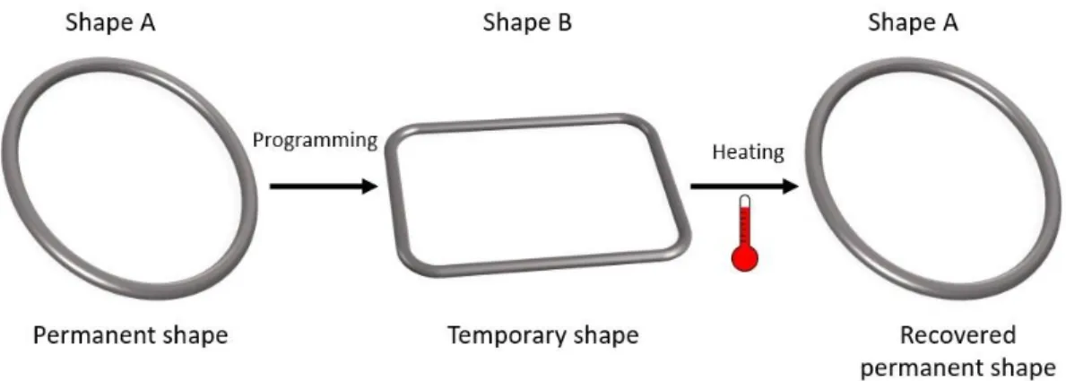
On the other hand, shape memory polymers (SMPs) exhibit a change of shape due to a variation of temperature and they generally actuate in a non-liquid media. SMPs are formed by soft segments (amorphous segments) and hard segments (crystalline segments). The changes in shape are caused by microstructural changes of these segments. They are commonly based on copolymers of polyurethanes and polyetheresters [88].
28 The actuation mechanism of SMPs starts by having a permanent shape A that could be deformed and fixed into a temporary shape B. After application of the thermal stimulus, the polymer could recover its initial permanent shape A. Figure 2.10 shows schematically this activation mechanism. In addition to temperature variations, there are some SMPs able to respond to changes in light, electric or magnetic fields and other stimuli.
Applications of SMPs are in medical devices [89][90][91], soft robotics [92][27], smart electronic devices [93], among others.
Figure 2.10. Actuation mechanism of the thermally induced shape memory effect in SMP.
2.4.3.2 Photo-responsive polymers
Photo-responsive polymers respond to electromagnetic waves by changing their properties such as viscosity, conductivity, solubility, morphology, and so on [94]. The photo-response is obtained by attaching photo-sensitive groups such as O-nitrobenzyl or hyperbranched polyglycerols to the polymer backbone. The response of these polymers strongly depends on their photon energy absorbance capacity. This photon energy absorbance capacity is related to the energy band-gap of the corresponding photosensitive group [95].
The major advantage of photo-sensitive polymers is that they could be stimulated remotely and the modulation of wavelength, intensity or irradiation time of the electromagnetic transmitter could be relatively easy [94][96][97]. However, the light of the environment should be highly controlled to avoid interferences, which can be difficult in some cases.
29 Moreover, the scarce light penetration inside bodies should be considered for biological applications [98].
The most popular application of photo-responsive polymers is in drug delivery. In this case, polymers change their morphology in function of incident electromagnetic waves which produces swelling or degradation. After that, the content inside the polymer can be released [97], as schematically shown in Figure 2.11.
Figure 2.11. Schematic representation of a photo -responsive polymer actuation in drug delivery.
2.4.3.3 Electro-responsive polymers (electroactive polymers)
Electroactive polymers can be stimulated to bend, stretch or contract by using electrical excitation [99]. The electroactive behavior of these materials is achieved by chemical modifications of the polymeric structure or by the incorporation of elements able to promote such behavior, e.g. the incorporation of particles sensitive to electrical stimuli. Because of their ability to emulate some biological operations, the most attractive applications for these polymers are in biomimetics as artificial muscles or as actuators in biological inspired robotics [100].
Electroactive polymers can be divided into two categories according to their activation mechanism:
• Electronic electroactive polymers (eEAPs) • Ionic electroactive polymers (iEAPs).
30 Electronic electroactive polymers (eEAPs) are mainly driven by electric field or coulomb forces. They could be: dielectric, piezoelectric, electrostrictive or ferroelectric polymers, as well as liquid crystal elastomers. The main advantage of these polymers is their ability to operate in air and not only in aqueous media, compared with other stimuli-responsive polymers. Moreover, they can hold the induced deformation or displacement while they are activated under DC voltage. In addition, they show a rapid response time of milliseconds [100]. These advantages make eEAPs good candidates for robotic applications [99][101]. However, the reported limitation of these polymers are the required activation fields considered as high (more than 100 V/µm) [70] [71].
Meanwhile, ionic electroactive polymers (iEAPs) are driven by transportation or diffusion of ions. Therefore, the activation of iEAPs consists of two electrodes and one electrolyte. Differently to eEAPs, the activation voltage of iEAPs is considered as low. iEAPs could be activated by applying 1-5 V and they can achieve higher strains in comparison with eEAPs. One of the limitations of these materials is that they must operate in a wet state or solid electrolyte. Moreover, they show slower response times by comparing with eEAPs. Slower response times in iEAPs are related to the ion transportation needed for their activation (which is a transportation of mass). Examples of iEAPs are ionic polymer gels, ionic polymer-metal composites or conducting polymers [100][101].
Table 2.1 shows the general classification of the electroactive polymers (EAPs), including examples of each category.
Table 2.1. Classification of EAPs and their characteristic examples.
Electronic EAP Ionic EAP
Dielectric EAP Ionic polymer gels Electrostrictive EAP Conductive polymers
Ferroelectric polymers Ionic polymer metallic composites Liquid crystal elastomers
31
2.4.3.4 Magneto-responsive polymers (Magnetoactive polymers)
Magnetoactive polymers respond to changes in magnetic fields. They are hybrid materials composed by magnetizable particles embedded in a polymeric matrix [102]. In these materials the magnetic and mechanical properties are coupled each other [20].
First reported classifications of magnetoactive polymers handle two main categories based on the kind of polymeric matrix. These two categories are: ferrogels (also called magnetoactive polymer gels) and magnetoactive elastomers (also called magnetorheological elastomers). However, some researches in magnetoactive polymers based on other kind of polymeric matrixes, such as thermoplastic or thermosetting, have also been reported [102][103][104].
A ferrogel is formed by a cross-linked polymer network containing a ferrofluid, which is a colloidal dispersion of monodomain magnetic particles [13]. Magnetoactive elastomers are composed of high elastic polymeric elastomers with micromagnetic particles [105].
In 2017, Musaddique et al. reported magnetoactive polymers based on thermoplastic or thermosetting polymers as a third category in the classification of magnetoactive polymers. This third category was called magnetic plastics [106]. For this thesis, the classification of magnetoactive polymers will be treated according to the diagram shown in Figure 2.12 (adapted from [106]).
As polymers are in general diamagnetic materials, the actuation mechanism of magnetoactive polymers occurs when an external magnetic field produces a force to the embedded magnetic particles, producing a response of the whole material. This bulk response is mainly attributed to the interfacial interactions between magnetic particles and the polymer [107]. Magnetoactive polymers exhibit two different types of response in presence of an external magnetic field which are: the response by magnetic moments or torques, and the response by magnetic induced normal forces [108].
32
Figure 2.12. Classification of magnetoactive polymers according to the used polymeric matrix (adapted from [106]).
Usually, embedded magnetic particles are ferromagnetic or ferrimagnetic materials, such as iron, nickel, cobalt and some iron oxides. These particles exhibit similar behavior although they are different in structure. In a ferromagnetic material the adjacent magnetic moments are parallel, and their magnitude is uniform, as schematically shown in Figure 2.13a. In a ferrimagnetic material adjacent magnetic moments are antiparallel, however, net magnetic moment results from the difference between their unequal magnitudes, as illustrated in Figure 2.13b [109].
Figure 2.13. Arrangement of magnetic moments in (a) ferromagnetic materials and (b) ferrimagnetic materials .
33 Ferromagnetic and ferrimagnetic materials in bulk present regions called Weiss domains or magnetic domains at temperatures lower than their Curie temperature. Such domains are small regions (from 20 nanometer to some micrometers [110]) within magnetic moments or net magnetic moments are aligned to the same direction as shown in Figure 2.14a. However, if an external magnetic field (H) is applied, magnetic moments start to move to the direction of the field (Figure 2.14b). This process is called magnetization (M) [111][112].
Figure 2.14. (a) Representation of the domains inside ferromagnetic and ferrimagneti c materials. W hen they are under a n external magnetic field H, they start to move to the
direction of the field (b) in order to be parallel to it like in (c).
Ferromagnetic and ferrimagnetic materials reach their saturation magnetization (Ms) when almost all their magnetic moments are aligned parallel to the external magnetic field (H), as shown in Figure 2.14c. However, when the external magnetic field is removed, these materials do not relax back to zero; instead, they retain some degree of magnetization (remanent magnetization). Thus, the external magnetic field must be reversed (-H) to drive the magnetization to zero again. The negative magnetic field required to drive magnetization to zero is called the coercive force (Hc). When the material is repeatedly magnetized in the positive and negative direction, the graph of magnetization (M) versus magnetic field (H) describes the hysteretic curve shown in Figure 2.15. The dash line shown in this figure represents the magnetization obtained when the material is magnetized for the first time [111][112].
34
Figure 2.15. Representative hysteretic behavior of ferromagnetic and ferrimagnetic materials.
The magnetic response of ferromagnetic and ferrimagnetic materials show size-related effects [110]. If such materials are presented in separated nanoparticles instead of bulk, they will show a different magnetic behavior.
Magnetic nanoparticles are considered as single-domains due to their sizes (usually less than 20 nm). Magnetic moments in nanoparticles are randomly oriented in the absence of an external magnetic field. When an external magnetic field is applied, the magnetic moments of the nanoparticles exhibit spin rotation and tend to have an orientation parallel to the field [113]. The single-domain condition permits the magnetic moments to move freely with the external magnetic field, as shown in Figure 2.16. Moreover, if the external magnetic field is removed, the single-domain condition of magnetic nanoparticles allows to recover their zero magnetization without hysteretic losses. This magnetic behavior is called superparamagnetism [112][113]. Figure 2.17 shows the characteristic magnetization curve of a superparamagnetic material.
![Figure 2.12. Classification of magnetoactive polymers according to the used polymeric matrix (adapted from [106])](https://thumb-eu.123doks.com/thumbv2/123doknet/14693876.745825/44.918.300.683.98.359/figure-classification-magnetoactive-polymers-according-polymeric-matrix-adapted.webp)