HAL Id: hal-00647869
https://hal.inria.fr/hal-00647869
Submitted on 2 Dec 2011
HAL is a multi-disciplinary open access
archive for the deposit and dissemination of
sci-entific research documents, whether they are
pub-lished or not. The documents may come from
teaching and research institutions in France or
abroad, or from public or private research centers.
L’archive ouverte pluridisciplinaire HAL, est
destinée au dépôt et à la diffusion de documents
scientifiques de niveau recherche, publiés ou non,
émanant des établissements d’enseignement et de
recherche français ou étrangers, des laboratoires
publics ou privés.
Simulation of the RPL Routing Protocol for IPv6 Sensor
Networks: two cases studies
Leila Ben Saad, Cedric Chauvenet, Bernard Tourancheau
To cite this version:
Leila Ben Saad, Cedric Chauvenet, Bernard Tourancheau. Simulation of the RPL Routing Protocol
for IPv6 Sensor Networks: two cases studies. International Conference on Sensor Technologies and
Applications SENSORCOMM 2011, Sep 2011, Nice, France. �hal-00647869�
Simulation of the RPL Routing Protocol for IPv6 Sensor Networks: two cases studies
Leila Ben Saad
CITI INSA-Lyon, ENS Lyon, INRIA Universit´e de Lyon
Villeurbanne, France [email protected]
Cedric Chauvenet
Watteco Inc. CITI INSA-Lyon - INRIA
La garde, France [email protected]
Bernard Tourancheau
CITI INSA-Lyon - INRIA Universit´e Lyon1 Villeurbanne, France [email protected]
Abstract—The routing protocol for low power and lossy networks (RPL) was recently designed in the ROLL working group at IETF. Few simulation tools exist that enable its evaluation in order to prepare for its real deployment. In this paper, we provide a new evaluation of this protocol with two approaches using two different simulators adapted to our needs. We first evaluated the value of mobile sinks in wireless sensor networks to extend the network lifetime using a sensor network simulator, WSNet, augmented by our own RPL module. We then focus on the performance comparison of simulated sensor networks and real powerline communication networks (PLC) using the RPL capable COOJA simulator augmented by our own PLC module. In each case, we justify the simulator choice, describe the tools implemented and present the obtained results. Our studies give two new RPL evaluations and show the interest of choosing a simulation tool adapted to the targeted study with the associated software developments. As a conclusion, we demonstrated how these two case studies can be combined in a heterogeneous network architecture to extend its global lifetime.
Keywords-Network Simulation, RPL, PLC, IPv6, Mobile Sinks, Energy Optimization, WSN, 802.15.4, Interoperability, Hybrid Network.
I. INTRODUCTION
Recently, significant studies have been conducted to en-able the convergence of sensor networks with the IP world and the connectivity of smart objects to the Internet. The IETF Working Group IPv6 over Low power Wireless Per-sonal Area Networks (6LoWPAN) proposed an RFC [1] to enable IPv6 packets to be carried over IEEE 802.15.4. Eventually, the IETF Working Group Routing over Low power and Lossy networks (ROLL) designed a routing protocol named IPv6 Routing Protocol for Low power and Lossy Networks (RPL). RPL was proposed because none of the existing known protocols such as AODV, OLSR or OSPF met the specific requirements of Low power and Lossy Networks (LLN), see [2]. The RPL protocol targets large scale wireless sensor networks (WSN) and supports a variety of applications e.g., industrial, urban, home and buildings automation or smart grid. The ROLL working group charter stipulates that the designed routing protocol should operate over a variety of different link layers, including but not limited to low power WSN. This feature requires the RPL protocol to support heterogeneity in LLN, for instance with
the use of WSN and Power Line Communication (PLC) technologies.
In this paper, we evaluate the performance of the RPL protocol in two cases dealing with low power WSN and low power PLC. This paper is organized as follows. In Section 2, related work is reviewed. Section 3 presents the RPL protocol. Section 4 describes the implemented modules for the simulation of RPL on WSNet [3] and Cooja [4]. In Section 5, the performance evaluation of RPL in the case of WSN with mobile sink nodes and PLC nodes is provided. Section 6 concludes the paper and discuss our future work.
II. RELATED WORK
Recently, several RPL simulations and implementations have been provided. In the internet draft [5], the RPL per-formance is evaluated by considering several routing metrics (i.e., path quality, delay bound for P2P routing, routing table size, control packet overhead, loss of connectivity) in real-life deployment scenarios. The simulator used in this study is OMNET++/Castalia [6]. In [7], the authors simulated RPL on OMNET++ to analyse its stability delays. In [8][9], the authors studied the multipoint-to-point performance of RPL as well as some suggested broadcast mechanisms. The sim-ulations have been performed on NS2. In [4][10] the authors proposed a framework for RPL simulation, experimentation and evaluation. This framework is composed of three parts: the Contiki operating system [11], the COOJA [4] / MSPSim [12] simulator and the ContikiRPL implementation [10]. At Berkeley and Johns Hopkins universities, an open-source implementation of RPL in BLIP-2.0 for TinyOS 2.x [13] is under development. We provide in the following a RPL con-trol message simulator based on the WSNet [3] / WSim [14] WSN simulator. There are also several other RPL industrial non-open source implementations.
Despite the fact that several studies and implementations have been conducted to evaluate the performance of RPL, to our knowledge, there has been no evaluation of RPL in the case of mobile sink nodes and low power PLC nodes.
III. PRESENTATION OF THERPLPROTOCOL
RPL [15] is a routing protocol designed for low power and lossy networks and targets networks with thousands
of nodes. RPL supports the multipoint, point-to-multipoint and point-to-point traffic. The basic idea of RPL is that the nodes organize themselves by forming a Destination Oriented DAGs (DODAGs) rooted towards one sink (DAG ROOT) identified by an unique identifier DODAGID. The DODAGs are optimized according to an Objective Function (OF) identified by an Objective Code Point (OCP), which indicates the constraints and the metrics in use [16] (e.g., hop count, latency, expected transmission count, energy, . . . ). Each node is assigned a rank which determines its relative position in the DODAG. The rank increases down et decreases up.
RPL uses the concept of DAG INSTANCE, which is a set of multiple DODAGs. A node can be a member of multiple DAG INSTANCEs but can belong to at most one DODAG per DAG INSTANCE. RPL constructs and maintains the upwards routes of the DODAGs by the transmission of DODAG Information Object (DIO) messages. DIO messages contain many informations: RPL INSTANCE, DODAGID, RANK, DODAGVersionNumber. The transmission of DIO messages by a node is regulated by a trickle timer [17] to eliminate redundant control messages. Each node monitors its neighbors’ DIO messages before joining a DODAG. Then, it selects a DODAG parent set from its neighbors ac-cording to the cost they advertise and eventually computes its RANK. Destination Advertisement Object (DAO) messages are aimed at maintaining downward routes. Sending a packet to the DAG ROOT consists in selecting the preferred parent with lower rank. Any node in RPL can send a DODAG Information Solicitation (DIS) message to solicit a DIO message from its neighborhood.
To repair the topology of the DODAG and allow nodes to join a new position, the DODAG ROOT increments the DODAGVersionNumber to create a new DODAGVersion. This operation is called global DAG repair. RPL also sup-ports other mechanisms to allow local repair within the DODAG Version. For example, the node can detach from the DODAG, advertise a rank of INFINITE RANK to inform its sub-DODAG, and finally re-attach to the DODAG.
IV. IMPLEMENTED MODULES FORRPLSIMULATION A. Simulator choice
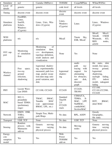
Table I compares the technical features of existing simu-lators. We needed open-source simulators in order to easily implement our research platforms.
We chose to simulate RPL with mobile sink nodes on the event-driven simulator for wireless networks WSNet, because the addition of any new feature does not need to modify the core of the simulator and can be done easily. Moreover, a mobility module was already implemented to ease the implementation of any moving scheme, like sink nodes for instance. Notice that when this study was started, no existing RPL open source implementation in a simulator was available.
Simulator ns2 Castalia OMNet++ TOSSIM Cooja/MPSim WSim/WSNet Level of
details generic generic code level all levels all levels Timing discrete event discrete event discrete
event discrete event discrete event Simulator platforms FreeBSD, Linux, SunOS, Solaris, Windows (Cygwin)
Linux, Unix, Win-dows (Cygwin)
Linux, Windows (Cygwin)
Linux Linux,(Cygwin)Windows
WSN
platforms n/a n/a MicaZ
Tmote Sky, ESB, MicaZ MicaZ, Mica2, TelosB, CSEM Wisenode, ICL BSN nodes, eZ430 GUI sup-port Monitoring of simulation flow Monitoring of simulation flow, c++ development, topology definition, result analysis and visualization
None Yes None
Wireless channel Free space, two-ray ground refection, shadowing lognormal shadow-ing, experimentally measured, path loss map, packet recep-tion rates map, tem-poral variation, unit disk lognormal shadow-ing multi-path ray-tracing with support for attenuating for obstacles, unit disk, directed graph
file static, disk model, free space, tworay ground, lognormal shadowing, rayleigh fading, ITU indoor model, nakagami fading PHY Lucent Wave-Lan DSSS CC1100, CC2420 CC2420 CC2420,TR1001
CC1100, CC1101,CC2500, CC2420 MAC 802.11, preambule based TDMA (preliminary stage) TMAC, SMAC, Tunable MAC (can approximate BMAC, LPL, etc.) Standard TinyOS 2.0 CC2420 stack CSMA/CA, TDMA, X-MAC, LPP, NullMAC, contikiMAC, SicslowMAC DCF, BMAC, ideal MAC Network DSDV, DSR, TORA, AODV
Simple Tree,
Multi-path Rings No data RPL, AODV Greedy Geographic, file static Transport UDP, TCP None No data UDP, TCP None Sensing Random process with Mannasim add-on Generic moving time varying physical process No data Moving nodes Generic moving time varying physical process Energy con-sumption model Yes Yes With Power TOSSIM add-on Yes Yes Table I
OPEN-SOURCESIMULATORSCOMPARISON
Our PLC motes development was conducted under the Contiki OS. COOJA is the simulator natively integrated into Contiki and it was a natural choice. COOJA runs as a glue between a hardware emulator (MSPsim, Avrora) and Contiki. Thus, it can directly run Contiki OS code, without modification. As a result, the ContikiRPL implementation is directly executable in COOJA. Moreover, it has a friendly GUI that made it ideal for easy learning and prototyping at the application level. Several plugins provide a fine grained vision of the simulated network. Various media and platforms are supported, forming a good starting point for our PLC components implementation.
B. WSnet simulator
A RPL module was implemented at the network layer in the WSNet simulator according to RPL draft version 5. The main features of this module are DODAGs building, rank computation and packets forwarding. The metric used to construct the DAG and determine the rank is hop count. To build the DODAGs, DAG ROOTs start by sending DIO packets containing: RPL INSTANCE, DODAGID, RANK, DODAGVersionNumber and OF. The nodes listen for DIOs and use their informations to join a new DODAG and
compute their rank. To that end, every node scans all its candidate neighbors and selects the current best parent by considering the OF. The nodes determine their own rank by adding the preferred parent rank to a RankIncrease value. The RankIncrease may vary from 1 to 16. Then, the nodes retransmit their own DIO packets to update the DoDAG and inform other nodes about the changes. The packets are routed to DAG ROOTs by the selection of the preferred parent with the lowest rank. The global DAG repair was implemented to reconstruct the network topology in case of broken links. The transmission of DIO messages by nodes is regulated by a trickle timer to suppress redundant control messages. The trickle timer interval for emitting DIO messages was initially fixed to one second and then incre-mented exponentially over the simulation time as specified in [17]. The routing module was used with chipcon radio CC1100 with 250 kbps data rate and implemented over IEEE 802.15.4 MAC and PHY layer specifications.
In the energy module, the current consumption values in transmit and receive mode were respectively fixed to 16.9 mA and 16.4 mA, as stated in [18]. In the application module, all the data packets generated by the sensors are fixed to 127 bytes (IEEE 802.15.4 MTU) and destined to the DODAG ROOT. Every minute, a packet is sent to the sink according to a Constant Bit Rate (CBR) sampling. The traffic supported in the application is multipoint-to-point. Therefore, only upwards routes were considered and DAO messages advertisement was configured to be entirely disabled. The mobility model in WSNet was modified to allow sink nodes to move according to our different moving schemes.
C. Cooja simulator
The ContikiRPL implementation works straightforwardly in COOJA and thus does not require any modification on our new platform. The ContikiRPL implementation is based on RPL draft version 18. It handles DIO, DIS, DAO, DAO-ACK, trickle timers management, local and global repair, ETX and Hop Count metrics.
1) PLC Nodes Implementation: None of the Hardware used in our PLC components are currently implemented in COOJA. Our PLC platform implementation relies on the existing Berkeley Telos [19] platform implementation in MPSim. This platform is composed of a MSP430 micro-controller and a CC2420, 802.15.4-compliant radio transceiver. We customized it to fit our low power PLC components [20] behavior. Notice that the Telos platform uses a f1611 version of the MSP430 MCU whereas our PLC nodes use a f5438 version. RAM/ROM capability modifications have been made to fit f5438 capabilities. A new implementation has been created in MSPsim to fit these differences. Other differences have limited impact on the PLC components performances and are not considered.
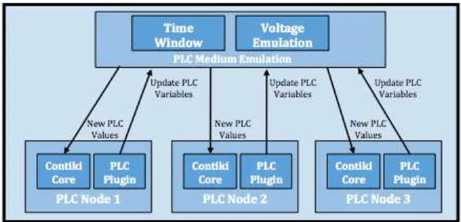
The PLC transceiver is the component with the most important impact on the node behavior, so its specificities were carefully implemented to have a precise simulation. Figure 1 shows an overview of the PLC implementation architecture in COOJA. As the MAC layer of the PLC node is implemented in the transceiver itself, new MAC drivers have been implemented in the Contiki core.
Figure 1. A simulated PLC environment in COOJA
2) Powerline medium Implementation: There is no well-adopted models for PLC simulation. We used the Directed Graph Radio Medium (DGRM) implementation of COOJA to create a PLC medium. We extended it with a node plugin in order to synchronize all simulated PLC nodes with a voltage emulation. This plugin updates the voltage emulation every 100µs on each node and triggers the computation of the communication windows on each PLC transceiver. Links are oriented, enabling to create asymmetric links, a common case in PLC networks. Every link created presents a success ratio and a delay configuration parameters. Links’ delay are not relevant on PLC networks, because the speed of signal propagation on electric wires was orders of magnitude smaller than the upper networking layer delays on low power PLC. Success ratio enables to inject real link measurements into the simulator.
3) COOJA developments: Our PLC medium implemen-tation creates a voltage emulation signal, computes the time windows where the PLC transceiver can transmit data, and updates a value in the Contiki core according to this computation. The voltage emulation consists in a sinus computation, where amplitude, frequency and phase can be set. The time window is computed according to the PLC transceiver specificities. It creates a transmitting-enable time window around the increasing zero-crossing voltage. This time window computation updates a value in the Contiki core that will impact the transceiver behavior. A PLC node plugin has been implemented to synchronize every node on the same electrical phase and trigger the time windows computation with a 100µs granularity. This plugin relies on the ”tick loop” to synchronize all simulated nodes. The PLC medium implementation triggers the PLC values computation to check if the PLC transceiver of the simulated node is able to transmit or not.
4) Hardware Implementation: The PLC transceiver im-plementation in MSPsim is based on the CC2420 with data rate modification. A new chip has been created with the same architecture as the CC2420 and the symbol period has been adjusted to 16µs to fit the PLC transceiver baud rate with Hamming code correction. CC2420 can continuously transmit data whereas the PLC transceiver sends data bursts around the uprising zero-crossing of the voltage. With the hamming correction error, the PLC transceiver sends bursts of 12 bytes each 50 Hz voltage period. The implementation respects this physical indentation.
5) Contiki developments: A modified version of the CSMA implementation in Contiki has been created to han-dles the backoff computation and the retry mechanism of the PLC chip. Radio duty cycling (RDC) mechanisms are not used over PLC but its implementation offers useful mechanisms such as no-ack and collisions detection. For a PLC simulated node, the relevant parts of these features have been added to the original implementation to create a dedicated RDC layer. Finally, a new low level driver has been created to synchronize the transmission of the simulated PLC chips with the Contiki core variables. This reflects the time window computed into the PLC medium implementation into the COOJA simulator. This driver waits for the time window before beginning to transmit a packet. This driver also handles the chip specific CCA mechanism.
V. PERFORMANCE EVALUATION OFRPL
In this Section, we evaluate the performance of RPL on the modified simulators by considering two case studies: mobile sink nodes and PLC nodes.
A. Case of mobile sink nodes
The WSNs are often composed by a large number of battery-operated sensors, which have a limited energy sup-ply. The sensors play at the same time the role of source nodes by generating data and relay nodes by forwarding the data of nodes farther away from the sinks. Thus, the sensors near the sinks are more likely to use up their energy much faster than distant nodes because they carry heavier workloads. Therefore, they become hot-spots. The hot-spot rapid energy depletion prevents farther nodes from relaying their data to the sinks. Consequently, the network lifetime ends prematurely. Moving the sinks even infrequently can partially solve this hot-spot problem and increase the net-work lifetime [21][22]. For this reason, the evaluation of the performance of RPL with multiple mobile sinks is needed to determine their best placement over time.
To evaluate the RPL performance in case of mobile sink nodes, we investigate the network lifetime (i.e., the death time of the first sensor), the sensors residual energy and the packet overhead. Moreover, we make a comparative study with different mobility schemes: RPL Static, RPL Random, RPL Energy, RPL Weight. In the first scheme, the sinks are
fixed. In the second scheme, the sinks are moving randomly among the sensor nodes. In the third scheme, the sinks are moving towards the nodes with the highest energy. In the fourth scheme, the sinks are moving towards the leaf node of the DODAG, which has the highest weight wi[23].
This weight is a function of three parameters influencing the network lifetime: hk
i is the number of hops from sensor
node i to its DAG ROOT at position k, ei is the residual
energy of sensor node i and bi is the number of its
1-hop neighbors. The exact weight calculation is as follows: wi = βhkiei +γbi where β and γ are coefficients of
normalization. They mitigates the effect of scale since the measurement units are different. The moving schemes are performed only during the periods multiple of the periods of DAG repair. The number of sensors used in the simulation ranges from 100 to 1600 nodes whereas the number of sinks is fixed to three.
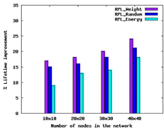
Figure 2 shows the lifetime gain as a function of the network size for different moving schemes with respect to the case of RPL with static sinks. The results shows that the lifetime improvement increases with the size of the network. This straightforwardly proves that using mobile sinks in RPL is more beneficial in large scale networks. It is also observable that the lifetime gain obtained in RPL weight scheme is better than the other strategies independently of the size of the network. Moreover, the lifetime improvement induced is about 24% in network with 1600 nodes.
Figure 2. Network Lifetime improvement as function of network size
Figure 3 compares the percentage of sensors residual energy as function of the network size at network lifetime end. The energy left unused at the end of network lifetime in mobile sinks schemes is notably lower than in the case of static sinks. This is due to the fact that sinks mobility changes the nodes acting as relays frequently and leads to balanced energy consumption among nodes. Nevertheless, RPL Weight results in the best distribution of the available energy on the sensors since it leaves the smallest amount of unused energy at the end of network lifetime.
In Figure 4, we analyze the amount of data packets transmitted (including forwarded) and the ICMPv6 control
Figure 3. Pourcentage of sensors’ residual energy at network lifetime end.
Figure 4. Packets transmitted : Control packets and Data packets (including forwarded data)
packets (DIO messages) transmitted by each node. With RPL Static scheme, the nodes near the sinks (e.g, node id 778) has more data traffic than other nodes because they have to transmit their own data in addition to farther away nodes data. However, for leaf nodes (e.g., 1401), the amount of data packets transmitted is smaller than middle or close to the sink nodes ones. This is because they do not have to act as forwarding nodes. By moving the sinks according to RPL Weight, the nodes playing the role of relay nodes change and the data traffic becomes more balanced among all the nodes. As shown in Figure 4, the majority of nodes have a comparable amount of data packets transmission. Moreover, the control overhead is very small in comparison to data packets. It is also not highly increased in spite of the mobility of sinks. This can be explained by the fact that the sinks move only during the periods of DAG repair.
B. Case of PLC nodes
PLC nodes are not energy constrained, so that they can play the role of sinks presented in the previous Section. Relying on the IPv6 design, and the 802.15.4 adaptation over PLC presented in [24], a lightweight IPv6 hybrid stack was designed over PLC and 802.15.4 with a unique 6LoWPAN adaptation [25]. As a result, these sinks become PLC-RF
bridges that form a PLC backbone to connect the wireless network. Considering the hypothesis of a limited number of sinks, we consider that a small amount of PLC nodes will be equipped with a dual physical stack. According to the previous proposition, these bridges will be moved periodically to distribute energy consumption efficiently. In such a context, we should determine the ability of the PLC network to fulfill a ”LLN backbone” role. Moreover, depending on the traffic volume and RF performance, the PLC backbone may induce losses, additional latency and/or decrease the overall throughput across the network.
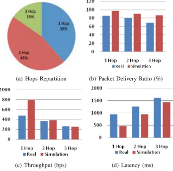
In order to evaluate the performances of this backbone, we measured the performances of a real and a simulated PLC network implementing the RPL network stack. We observed hops distribution, packet delivery ratio (PDR), throughput and latency. Our test bed was a 2 floors research laboratory, composed of 25 rooms. We used 6 PLC nodes and a border router. PLC nodes were randomly plugged in outlets. The Border router was never moved. After topology establishment, the border router sends 3 series of 30 pings to each node it has in its routing table with a delay of 2 seconds per hop between each ping. Once the 3 series of 30 pings were done, we moved all the PLC nodes into a new room, and repeated the scenario. The power grid electrical network was impacted by daily life activity. The simulation platform first replayed the scenarios in the testbed topology but with ideal links in order to quantify the looseness of the PLC media. The simulated nodes used the same software as real nodes.
(a) Hops Repartition (b) Packet Delivery Ratio (%)
(c) Throughput (bps) (d) Latency (ms) Figure 5. Performances of real and simulated PLC network
Figure 5(a) shows that from the border router location, the RPL protocol reached all the 6 PLC nodes in any
room through a 3 hops maximum path. This points out the reliability, connectivity and forwarding cost reduction that is potentially available in such hybrid networks. Furthermore, this also shows that a small amount of PLC nodes may be enough to form a PLC backbone. For instance, the previous hypothesis of 3 sinks in Section V.A, shows the gain that can be obtained using 3 RF-PLC bridges for an entire small building. As expected, in Figures 5(b), 5(c), 5(d) the performances of the PLC network for PDR, Throughput and Latency decrease with path length e.g., number of hops. Though, the maximum paths’ length of 3 limits the performances downgrade. Throughput is less impacted by real PLC links because it is only computed for successful transmissions. Latency performance shows that real PLC links induce more link layer retries on real PLC networks. Notice that in the simulation, even with ideal links, 100% PDR is not reached because of collisions with control messages traffic.
VI. CONCLUSION
Our studies show that there are several possibilities for LLNs simulation. In particular, the RPL routing protocol is already supported in Contiki/COOJA. However, WSNet provides interesting capabilities for mobility management.
Our research provides new functionalities either in WSNet with the implementation of RPL for our needs in the context of sink mobility and in COOJA with the support of a new networking hardware, namely low power PLC.
With these improved simulators, the conducted exper-iments show the interest of RPL simulation in order to improve WSN lifetime by managing the sink mobility and to provide coherent routing in LLN heterogeneous platforms with wireless and PLC sensor networks.
REFERENCES
[1] G. Montenegro, N. Kushalnagar, J. Hui, and D. Culler, “Transmission ofIPv6 packets overIEEE802.15.4 networks,” IETF, RFC 4944, 2007.
[2] P. Levis, A. Tavakoli, and S. Dawson-Haggerty, “Overview of existing routing protocols for low power and lossy networks,” Draft, 2009.
[3] WSnet simulator http://wsnet.gforge.inria.fr/, 2010.
[4] N. Tsiftes, J. Eriksson, N. Finne, F. ¨Osterlind, J. H¨oglund, and A. Dunkels, “A framework for low-power ipv6 routing simu-lation, experimentation, and evaluation,” SIGCOMM Comput.
Commun. Rev., vol. 40, pp. 479–480, August 2010.
[5] J. Tripathi, J. de Oliveira, and J. Vasseur, “Performance Evaluation of Routing Protocol for Low Power and Lossy Networks (RPL),” IETF, Draft, January 2011.
[6] A. Varga and R. Hornig, “An overview of the OMNeT++ simulation environment,” in Int Conf on Simulation Tools
(ICST). ICST, 2008.
[7] M. Nuvolone, “Stability analysis of the delays of the routing protocol over low power and lossy networks,” Master’s thesis, Sweden Royal Institute of Technology, 2010.
[8] T. H. Clausen and U. Herberg, “Comparative Study of RPL-Enabled Optimized Broadcast in Wireless Sensor Networks,” INRIA, Tech. Rep. 7296, 2010.
[9] ——, “Multipoint-to-Point and Broadcast in RPL,” INRIA, Tech. Rep. 7244, 2010.
[10] N. Tsiftes, J. Eriksson, and A. Dunkels, “Low-power wireless IPv6 routing with ContikiRPL,” in Int Conf on Information
Processing in Sensor Networks. ACM/IEEE, 2010. [11] A. Dunkels et al., “Contiki-a lightweight and flexible
operat-ing system for tiny networked sensors,” 2004.
[12] J. Eriksson, A. Dunkels, N. Finne, F. Osterlind, and T. Voigt, “MSPsim-an extensible simulator for MSP430-equipped sen-sor boards.” 2007.
[13] M. Afanasyev, D. O’Rourke, B. Kusy, and W. Hu, “Het-erogeneous Traffic Performance Comparison for 6LoWPAN Enabled Low-Power Transceivers,” 2010.
[14] Wsim Simulator http://wsim.gforge.inria.fr/.
[15] T. Winter and P. Thubert, “RPL: IPv6 routing protocol for low power and lossy networks,” IETF, Draft, 2010.
[16] J. Vasseur, M. Kim, and K. Pister, “Routing metrics used for path calculation in low power and lossy networks.”
[17] P. Levis, T. Clausen, J. Hui, O. Gnawali, and J. Ko, “The trickle algorithm,” IETF, Draft, 2010.
[18] CC1100 datasheet focus.ti.com/lit/ds/symlink/cc1100.pdf. [19] J. Polastre, R. Szewczyk, and D. Culler, “Telos: enabling
ultra-low power wireless research,” in Information Processing
in Sensor Networks (IPSN). IEEE, 2005, pp. 364–369. [20] Watteco, “Wpc-ip product brief,” www.watteco.com, 2011. [21] L. Ben Saad and B. Tourancheau, “Towards an optimal
positioning of multiple mobile sinks in wsns for buildings,”
Int J On Advances in Intelligent Systems, vol. 2, no. 4, 2009. [22] ——, “Multiple mobile sinks positioning in wireless sensor networks for buildings,” in Int Conf on Sensor Technologies
and Applications (SensorComm). IARIA, 2009.
[23] ——, “Sinks Mobility Strategy in IPv6-based WSNs for Network Lifetime Improvement,” in Int Conf on New
Tech-nologies, Mobility and Security (NTMS). IFIP, 2011. [24] C. Chauvenet, B. Tourancheau, and D. Genon-Catalot,
“802.15.4, a MAC layer solution for PLC,” in AICCSA. ACS/IEEE, 2010.
[25] C. Chauvenet, B. Tourancheau, D. Genon-Catalot, P.-E. Goudet, and M. Pouillot, “Interoperable IPv6 sensor network-ing over PLC and RF media,” IJBDCN, vol. 6, no. 3, 2010.