On the Structure of Problem Variability: From Feature Diagrams to Problem Frames
10
0
0
Texte intégral
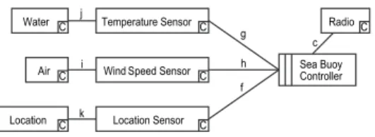
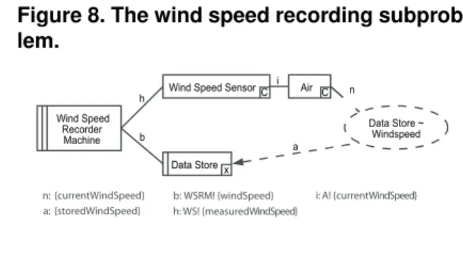
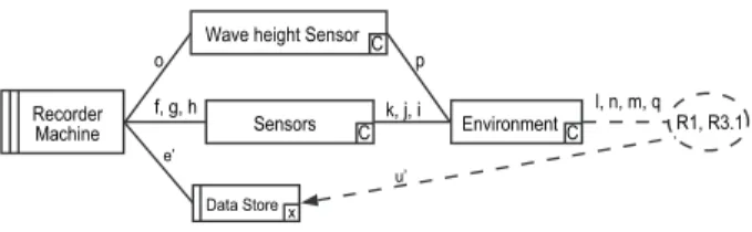
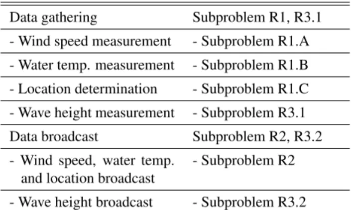
Figure

+2
Documents relatifs