Design of an Active Compressor Blade for Aeroelastic
Studies
by
Gordon Lewis Maahs
B.S. Engineering Science and Mechanics, Virginia Polytechnic Institute and State University (1996)
Submitted to the Department of Aeronautics and Astronautics in partial fulfillment of the requirements for the degree of
MASTER OF SCIENCE
at the
MASSACHUSETTS INSTITUTE OF TECHNOLOGY
February 1999
@
Massachusetts Institute of Technology 1999. All rights reserved.A ithnr
e"partment of Aeronautics and Astronautics January 29, 1999
Certified by.
/ / //Profe Carlos E. S. Cesnik Assistant Professor of Aeronautics and Astronautics Thesis Supervisor Accepted by
Chairman,
MASSACHUSETTS INSTITUTE OF TECHNOLOGYMAY
17
1999
LIBRARIES
V Professor Jaime Peraire Department Graduate Committee
I-o
i
I
-UII 1 •|
Design of an Active Compressor Blade for Aeroelastic Studies
by
Gordon Lewis Maahs
Submitted to the Department of Aeronautics and Astronautics on January 29, 1999, in partial fulfillment of the
requirements for the degree of Master of Science
Abstract
This thesis begins the development of a tool that will enable direct measurement of the unsteady aerodynamic response of a transonic compressor for use in flutter identification. The experimental apparatus, named the Active Rotor, will have active blades with individ-ual motion control. The Active Rotor Blades, proposed in this work, uses a spar-and-shell concept which consists of a flexible outer foam shell, structural spars, and piezoelectric actuators. The graphite epoxy spars both carry the load of the blade and induce shape changes of the blade from attached piezoelectric actuators. Control of a blade shape and position to the airflow allows new experiments to be performed in the area of flutter and unsteady aerodynamics.
A design study was performed to choose several of the material and geometrical proper-ties of the Active Rotor Blade. A NASTRAN/PATRAN finite element model was developed with these design parameters to calculate the stresses in the composite spars, the level of tip rotation available from piezoelectric actuation, and the strains seen by the piezoceramic under full centrifugal loads. The spar stresses and available actuation were within required ranges, but the strain predictions on the piezoceramics were near the ultimate. The com-posite spar modeling and piezoelectric actuation modeling were verified with experimental results.
The piezoceramics were protected from large tensile strains by bonding to the composite with a compressive prestrain. Experiments on the bond layer characterized its strength and ability to hold the desired precompression. Testing identified piezoelectric actuation under loads specific to the Active Rotor Blade: compression, release of compression, and tension. The piezoceramics were bonded to different composite layups with different Poisson's ratios to assess the effect of biaxial stress states. Results indicate that the biaxial stresses have a larger influence on actuation than the precompression. The piezoceramic was not observed to lose structural integrity or show a large loss in actuation when pulled significantly beyond its failure strain. The increased strength is attributed to the packaging designed for the Active Rotor.
Thesis Supervisor: Professor Carlos E. S. Cesnik
Acknowledgments
I would like to thank my advisor, Professor Carlos Cesnik, for allowing me a great amount of freedom in this project. Through his in-depth discussions and through his excellent teaching ability, he kept my work as a graduate student interesting and rewarding. I am thankful for his support. Thanks to Professor Jim Paduano for being patient with the continual structural and material problems that arose at every turn. And to Professor Paul Lagace whose overdeveloped sense of competition can't always match that of a student. Forget arm wrestling... softball, anyone?
Many thanks to the undergraduate research assistants that worked with me on this project. Andy Oury, who had the independence and motivation to work out several of the manufacturing details, and who was invaluable for getting the test equipment in a usable fashion. Anna Park, whom, despite the horrors of the machine shop, was always smiling and producing very nicely tapered composite spars. Mike Kim, who kept the assembly line of packaging piezoceramics running smoothly, and Paul Goulart and Matt Lockhart for their contributions.
I would like to thank John Kane, the TELAC lab technician, whose experience and humor was well appreciated, and John Rodgers, whose work on Active Fiber Composites kept me continually seeking his advice and borrowing from his supplies. And many thanks to Debashis Sahoo, who worked with me on the finite element modeling, and whom I am sure will do fantastic work in continuing the project.
I must thank those members of GTL and TELAC and that whole group of Draper Fellows (who somehow all found it convenient to graduate on time), that kept life a GFT.
I make a special thanks to my family for making all of this possible.
Funding for this research was provided under the Air Force Office of Scientific Research (AFOSR) Grant Number F49620-95-1-0280, and Grant Number F49620-95-1-0409: their support is gratefully acknowledged.
Contents
Abstract Acknowledgments Table of Contents List of Figures List of Tables Nomenclature 1 Introduction 1.1 Motivation 1.2 Background . 1.3 Scope of Thesis .2 Active Rotor Design
2.1 Requirements . ... 2.2 Active Rotor Concept ... 2.3 Material and Geometry Choices . .
2.3.1 Spar Study . ... 2.3.2 Foam Shell . ... 2.3.3 Piezoelectric Actuators . 2.3.4 Active Rotor Blade Component 2.4 Finite Element Modeling ...
2.4.1 Modeling Approach ...
2.4.2 Model Inputs ... ... 40
2.4.3 Model Verification ... ... . 41
2.4.4 Assessment of Active Rotor Requirements . ... 42
2.4.5 Conclusions from Finite Element Model . ... 43
3 Protection of the Piezoelectric Actuators 49 3.1 Precompression Options ... . . . . ... .. 49
3.2 Embedded Piezoceramics in Composite Materials . ... . . . 49
3.2.1 Classical Laminated Plate Theory . ... 50
3.2.2 Residual Thermal Strain Predictions . ... 54
3.2.3 Laminate Strength Predictions ... .. 55
3.2.4 Discussion ... ... .. .. ... ... 57
3.3 Surface Bonding Piezoceramics to Graphite-Epoxy . ... 61
3.3.1 Elastic Perfectly-Plastic Shear Lag Analysis . ... 61
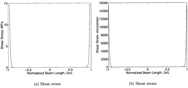
3.3.2 Results of Shear Lag Analysis ... ... 65
4 Active Spar Coupon Manufacture and Characterization 69 4.1 Coupon Types ... ... .. 69
4.2 Materials ... ... ... ... .... 70
4.3 Lead Manufacture ... ... 72
4.4 Piezoelectric Actuator Characterization ... . 74
4.4.1 Butterfly Curves ... ... 74
4.4.2 High Strain Piezoelectric Nonlinearities . ... . . 75
4.5 Surface Bonding Piezoceramics to Graphite-Epoxy Beams . ... 80
4.6 High Stress Actuation Nonlinearities ... ... 82
4.6.1 Background ... ... 82
4.6.2 Experimental Stress Dependence ... . 85
4.7 Summary ... .. .. ... 86
5 Coupon Experiments and Results 89 5.1 Approach ... ... ... 89
5.2 Goals ... ... ... 89
5.4 Creep Test ... ... 96
5.4.1 Static Creep ... . ... . ... .. 96
5.4.2 Extended Dynamic Actuation ... ... 97
5.4.3 Piezoelectric Creep ... ... . 98
5.5 Benchtop Actuation Test ... ... . 98
5.5.1 Setup ... ... ... .. 98
5.5.2 Results ... .... ... . 100
5.6 Tensile Test ... .... ... 103
5.7 Actuation Under Loading Test ... ... 105
5.7.1 Setup ... . ... . ... .. 105
5.7.2 Alignment Issues ... ... . ... 106
5.7.3 Results ... .... . ... .. 109
5.8 Summary ... . ... ... 117
6 Finite Element Model Development 119 6.1 Coupon FE Model ... ... ... . 121
6.2 Modeling Natural Frequencies ... ... 123
6.2.1 Material Properties ... ... 123
6.2.2 Thickness Reduction ... ... 124
6.3 Modeling Piezoelectric Actuation . ... .. . . 125
6.4 Modeling Results ... ... . .. . ... ... 126
6.5 Summary . ... . . . . . . . 127
7 Conclusions and Recommendations 131 7.1 Summary ... .. ... ... 131
7.2 Conclusions ... .... ... ... ... ... 134
7.3 Recommendations ... ... . ... 135
List of Figures
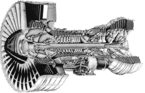
1-1 Cut-away view of a PW4000 engine ... .... 22
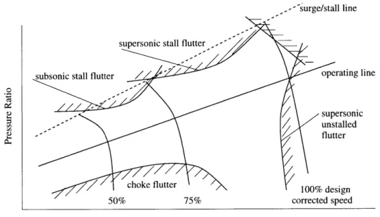
1-2 Typical operating map of a transonic compressor indicating observed regions of flutter. Adapted from [32]. . ... ... ... 23
1-3 Compressor map illustrating a ground certification test that failed to repro-duce flutter conditions. The flutter regions and working lines were estimated by Cumpsty [15]. ... ... .. ... 24
1-4 A 1960's fan blade with a part-span shroud . ... 25
2-1 Active rotor blade ... ... ... .. . 29
2-2 Active rotor blade actuation. Outer foam shell not shown. . ... 30
2-3 Spar model for sensitivity studies. The foam is not included in picture, only a single spar and its two piezoelectric actuators are shown. . ... 32
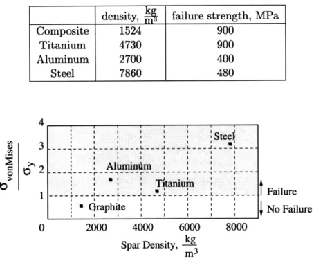
2-4 Spar material selection ... .... ... . 35
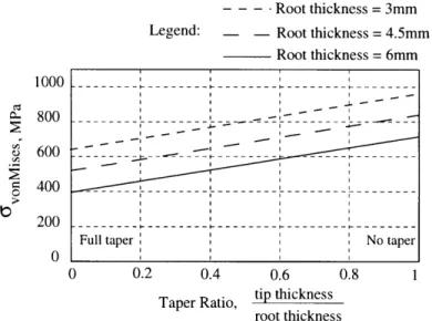
2-5 Spar Thickness and Thickness Taper Selection . ... 36
2-6 Spar orientation selection . ... .. . . . . . 37
2-7 Piezoelectric effect by domain movement of a poled ferrolelectric material . 39 2-8 Active Rotor NASTRAN/PATRAN finite element model ... 44
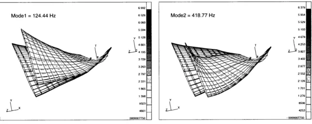
2-9 GE Fan C mode shapes simulated with the FE model built for the Active Rotor ... .. .... ... . ... . 45
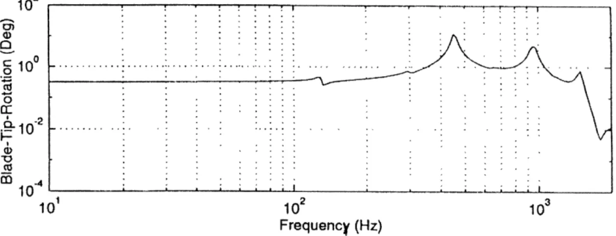
2-10 Transfer function between voltage to the piezoceramic and blade tip rotation 46 2-11 Spar stresses for smeared graphite-epoxy properties . ... 47
2-12 Strain on piezoceramic due to centrifugal loading . ... 48
3-1 Resultant forces and moments ... ... 52
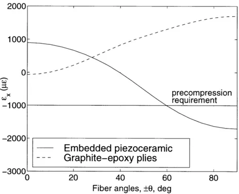
3-3 Residual thermal strains in the x direction for graphite-epoxy composite and embedded piezoceramics from cure (AT = -275°F). Layup used is
[Piezo/(±O)6sym ... . ... ... 56
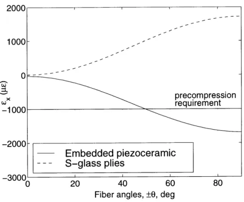
3-4 Residual thermal strains in the x direction for s-glass composite and embed-ded piezoceramics from cure (AT = -275 0F). Layup used is [Piezo/(+±)6]sym. 57 3-5 Residual thermal stresses and strains for graphite-epoxy composite and em-bedded piezoceramics from cure. Layup used is [Piezo/(O0)6sym]. Used as partial loading in strength analysis. ... .... . . 58
3-6 Residual thermal stresses and strains for s-glass composite and embedded piezoceramics from cure (AT = -275 0F). Layup used is [Piezo/(±O)6]sym. Used as partial loading in strength analysis. . ... 59
3-7 Failure stress for graphite-epoxy and s-glass composites. Stress (spanwise direction) for first ply failure of layup [Piezo/(0)]sym is found including6 thermal effects from cure described in Figure 3-5, 3-6. . ... 60
3-8 Double lap joint geometry ... ... . 62
3-9 Double lap joint forces ... . . ... 62
3-10 Bond strain displacement ... ... 63
3-11 Stresses and strains along the adhesive length for a bond thickness of .0254 mm (1 mil) ... ... ... 67
3-12 Maximum shear strain (edge shear strain) as a function of bond thickness . 68 4-1 Dimensions of template for all coupon types . ... 70
4-2 Bonding Kapton electrical leads to piezoceramic . ... 73
4-3 Experimental setup for bond cures ... .... 73
4-4 Lead cure exploded section ... ... 74
4-5 Coordinate system for piezoelectric material . ... . .. . 75
4-6 Measured butterfly curve of PZT-5A for transverse (1 direction) response. . 76 4-7 Measured piezoelectric actuation value for PZT-5A, d3 1, plotted as a function of actuated strain ... ... .. 77
4-8 Measured piezoelectric actuation value for PZT-5A, d3 1, plotted as a function of electric field ... .... ... 78
4-9 Field-Strain hysteresis for free piezoceramic PZT-5A at four different peak
strain levels. Five cycles plotted for each level. .... . 79
4-10 Beam cure exploded section ... ... 80
4-11 Precompressed bond cure ... .... ... .. 81
4-12 Data from Zhang[41] and Krueger[28] showing d constants as a function of loading perpendicular to the polar axis for PZT-5A. .... 83
4-13 Free butterfly curves for PZT-5A ... ... 85
4-14 Bonded butterfly curves of PZT-5A showing effects of compression .... . 86
5-1 Instrumentation diagram. Not all inputs were used for every test. ... . 91
5-2 Voltage divider with voltage follower. ... ... 92
5-3 RC circuit . . . . . . . . . . ... . . . . 92
5-4 Results of RC circuit analysis with 150 Volt sinusoidal input and a capacitor of 50nF. ... .. .. ... ... ... ... 94
5-5 Laser calibration curve ... ... ... 95
5-6 Creep of precompressed bond layer ... .... 97
5-7 Mean compressive strain during actuation ... ... 98
5-8 Actuated strain (the -680pE compression was subtracted) .... 99
5-9 Frequency response test setup. Top view. .... 99
5-10 Experimental frequency response setup. ... . 100
5-11 Transfer functions for coupon B, [20],,sym. The piezoceramics on opposite sides of the beam, Left Piezo and Right Piezo, have opposite signs, but only magnitude is shown. .... .... . . .. . . 101
5-12 Transfer functions for coupon A, [±20]6sym. The piezoceramics on opposite sides of the beam, Left Piezo and Right Piezo, have opposite signs, but only magnitude is shown ... . ... 102
5-13 Transfer functions for coupon A, [±2016sym. Each test was performed after the specimen had been held at the indicated strain level. .... 104
5-14 Schematic of Actuation Under Loading Test .... 106
5-15 Experimental Setup of Actuation Under Loading Test .... 107 5-16 Static strain readings on the composite and piezoceramics showing alignment. 108
5-17 Difference between strain gages on front side and back side of composite and piezoelectric materials for coupon type B [±20]sym and coupon type C [0/90]sym 109
5-18 Explanation of Actuation Under Loading variables. . ... 110
5-19 Transverse strain readings on the composite and piezoceramics showing the difference between layups. ... . ... 111
5-20 Actuation under static tensile load for coupon type C [0/90]sym. . ... 113
5-21 Actuation under static tensile load for coupon type B [±20]sym. ... 114
5-22 Residual actuation at 5 lbs after testing at indicated strain level. ... . 116
6-1 Example transfer function indicating measures of comparison to finite el-ement model. Composite spar modeling results are compared to natural frequencies, labeled 'la', 'lb'. Piezoelectric actuation results are compared to the static tip deflection, labeled '2'. ... .. 120
6-2 Front view of solid mesh for cantilevered finite element model of Coupon A [+20]6sym ... .. . . ... 122
6-3 Close up of corner mesh for cantilevered finite element model of Coupon A [±20]6sym ... ... ... 123
6-4 Finite element model and experimental comparison of transfer functions for coupon type B [±20]sym and coupon type C [0/90]sym . ... 128
6-5 Finite element model and experimental comparison of transfer functions for coupon type A [±20]6sym . ... .. ... .. 129
List of Tables
2.1 GE scaled Fan C characteristics ... ... 31
2.2 Some material and geometrical values for simplified blade model. Values in parentheses are the default values when other variables are being investigated. 34 2.3 Material inputs for simplified spar model. The composite failure strength was found for equivalent isotropic properties. . ... 35
2.4 Typical selected foam properties with forming techniques . ... 36
2.5 Comparison of solid state actuation materials (modified from [6]) ... 38
2.6 Piezoelectric properties obtained from Morgan Matroc . ... 41
2.7 Foam properties obtained from Rohacell ... . 41
2.8 Graphite-epoxy AS4/3501-6 ... ... ... . 42
2.9 Natural frequency comparisons . ... ... 42
3.1 Graphite-epoxy AS4/3506-1, s-glass and piezoelectric material properties.. 55
3.2 Precompression results for graphite-epoxy and s-glass [Piezo/(±+)6 sym . . 58
3.3 Piezoelectric properties and operating stress . ... 66
3.4 Shear lag property inputs ... ... . 66
4.1 Coupon type designation . ... . . . . . . . 70
4.2 Morgan Matroc PZT-5A Properties ... .... 70
4.3 Graphite-epoxy AS4/3506-1 properties ... .. 71
5.1 Experiments and coupon types (from Table 4.1) . ... 91
6.2 Thickness of several laminates of AS4/3501-6, measured with the epoxy layer (actual) and measured without the epoxy layer (effective). Peel plies obtained
from TELAC, MIT [29] ... ... ... 124
6.3 Iterations to converge to d3 1 . . . .. 126
Nomenclature
Roman
A Cross-sectional area
Aij Laminate extensional stiffness Bzj Laminate coupling stiffness
c Maximum distance from neutral axis
C Correction factor for flattened rectangular beams [5] d Adhesive elastic region length
dij Piezoelectric strain coefficient
DJ Laminate bending stiffness
Ei Young's modulus
E3 Electric field applied through thickness or 3-direction
F Centrifugal force
G, Gi Shear modulus
I Area moment of inertia
1 Adhesive length
L Length
m Mass
M Moment from centrifugal force
Mi, M,3 Resultant plate moment
Mr , MT Thermal resultant plate moment
N Number of plies in a laminate Ni, Nij Resultant plate force
P Force
Qi3 Reduced stiffness
Qij Transformed or rotated reduced stiffness
r Distance from the hub center
ro Hub radius
S Shear strength
t Thickness
T Temperature
T1 Stress applied in 1-direction
Tp Force per unit width
V Volume
Xt Longitudinal tensile strength Yt Transverse tensile strength
zz Distance from laminate middle surface to ply edge
z Distance from laminate middle surface
Greek
a, ai, ai Coefficient of thermal expansion
/ Skew angle
Ti- Shear strain
0o Middle surface shear strain
6
DisplacementEi Strain
E Middle surface strain
7r Thickness of adhesive
0 Fiber angle
i Middle surface curvature
uij Poisson's ratio
Coordinate of adhesive plastic region
a,ai Oy OvonMises T,7i Ty w Stress
Failure stress (yield or ultimate) von Mises stress
Shear stress Yield shear stress Rotational speed
Subscripts
act c efff
x, y, z p k 1, 2, 3 Actual Composite Effective Foam Laminate direction Piezoceramic Ply number Material directionChapter 1
Introduction
1.1
Motivation
Unwanted vibrations have plagued the users and designers of jet engines throughout its history. At low levels, blade vibrations lowers the performance and reduces engine life, and at high levels, vibrations can destroy the engine and jeopardize the safety of the crew and passengers. The vibrations important to jet engines can be classified into two categories: forced vibration and flutter. Forced vibration occurs when a blade experiences a force at or near one of its natural frequencies. In general, forced vibration is better understood, predictable, and can be included in the design of the engine. In contrast, flutter, perhaps the more serious of the two vibrations, is inadequately predicted. Flutter is a self excited fluid-structure interaction in which the air flow supplies energy to the blade. It is an instability where the resulting motion of the blades influences the aerodynamic forces, which in turn
impart more energy to the blades causing sustained levels of unacceptable vibrations. A cut-away diagram of an engine (Figure 1-1) shows the many types of rotating com-ponents found throughout a typical engine. The blades have a variety of shapes and sizes designed to accomplish different tasks, and the relatively high aspect ratio and high loading of the fan and high speed compressor make these blades susceptible to flutter problems.
A compressor map (Figure 1-2) represents the pressure ratio versus the mass flow through the engine and is a convenient method for displaying the regions of flutter. Several regions have been named due to trends noticed during testing, but the boundaries of these regions can be misleading and are continually being revised. The current lack of under-standing and predictive capability of flutter is illustrated by the Boeing 737-400 crash that
Figure 1-1: Cut-away view of a PW4000 engine
occurred in January 1989. Fan flutter was determined to be the cause of the crash [39]. The engine on the Boeing 737-400 was just a higher thrust version of the one used in the Boeing 737-300, obtained by increasing the rotational speed of the fan by between 2 and 3%. Because this increase was seen as a small change, the Federal Aviation Administration approved a ground certification test instead of the more complete and expensive in-flight test. The ground test differed from the in-flight test by using a larger bypass nozzle to better dissipate the temperatures found at sea level.
The effect of the increased nozzle is illustrated by Cumpsty [15] for a typical fan' in Figure 1-3. The top diagonal line is the design working line, and the bottom diagonal line is the measured working line found at the ground test. The curves with circles are measured lines of constant rotational speed. Cumpsty included a proposed 103% line as well as the shaded regions which estimate the flutter boundaries, based on typical compressor maps (e.g. Figure 1-2). Because the larger nozzle of the ground test reduces the pressure ratio, the measured working line at 103 % is clear of flutter, while the actual working line crosses into the flutter boundary. Due to the level of damage at the January 1989 crash, the cause was not definitive; it took two more failures on identical engines (no crashes resulted because of pilot action), and in-flight testing to determine that the engine had flutter problems.
--''-surge/stall line
subsonic stall flutter /operating line
supersonic
/
-unstalledflutter
choke flutter 100% design
50% 75% corrected speed
Mass Flow
Figure 1-2: Typical operating map of a transonic compressor indicating observed regions of flut-ter. Adapted from [32].
The mechanisms of flutter are not well understood. Beyond the obvious lack of predic-tive capability, this absence of understanding extends into the design phase of an engine. Without appropriate knowledge of flutter, there are no adequate ways of designing around it. An engine must undergo extensive testing, and when flutter problems are found, a series of corrections must be made. Unfortunately, since the causes are elusive, these corrections can deal only with the symptoms and have always added penalties to the engine perfor-mance. Part-span shrouds (Figure 1-4) can be included so a vibrating blade shroud rubs against its neighbor's shroud, increases its damping, and helps to reduce vibration. The shrouds, however, interfere with the air flow through the stage and introduce unnecessary flow perturbations. Hollow blades have a higher natural frequency compared to similar solid blades and have been observed to postpone flutter without altering flow properties. Their high manufacturing cost keeps this a difficult option. Other options, such as reducing rota-tional speed, or adding blade thickness also help to postpone flutter but come at a cost to the performance of the engine. A better understanding of flutter is needed to find possible ways of addressing flutter without the associated penalties and to identify the gaps in the current state of knowledge, such as those that lead to the January 1989 crash.
2.0 103
o Design Speed 1000% "tal"
1.8utter 90%,
S1.6-
Surge Line 1.4-80% . 1.2 - "Choke" Flutter 1,0 0.5 0.6 0.7 0.8 0.9 1.0 ri I tih DesignFigure 1-3: Compressor map illustrating a ground certification test that failed to reproduce flut-ter conditions. The flutflut-ter regions and working lines were estimated by Cumpsty
[15].
1.2
Background
Two modeling approaches, empirical, and physical, which is further divided into numerical and analytical, are introduced and their approaches are briefly discussed.
Empirical models are a mathematical fit to arbitrary parameters and have very limited predictive power [3]. The standard in industry today is to use empirical models. Ignoring the underlying mechanisms of flutter and finding problems by experimental testing is a quick way of determining if a particular engine under a particular set of operating parameters will flutter. However, testing the parameter space (including pressure, temperature, corrected speed, and weight flow) is impractical and the resulting compressor maps do not fully represent all relevant parameters, leading to distrust of such measures [26].
Physical models are based upon physical phenomenon and thus contain reliable predic-tive power. Clearly, physical models are superior to empirical models, but they come at a price. Gaining a fundamental understanding of the mechanisms that lead to flutter is a difficult task, in part due to the complexity of flutter and in part due to the hostile envi-ronment that makes experimental measurements difficult. Two types of physical models, numerical and analytical each have benefits and drawbacks.
Figure 1-4: A 1960's fan blade with a part-span shroud
Numerical methods start from first principles and can estimate very complex equations with computer algorithms. Yet the current computer capability is not able to solve what appears to be required for flutter; an unsteady, three-dimensional, transonic, viscous fluid flow [15]. Further, the method of interaction between the fluid dynamic algorithms and the structural dynamic algorithms is still under research [36]. However, computer progress is fast paced and significant advances are expected in the near future.
Even with the increasing power of computer modeling, analytical models still play an important role in engine design. Framing the problem in terms of basic elastic, aerodynamic, and stability theories provides insight not easily found in complex numerical models. An-alytical models attempt to capture dominant physical processes at the exclusion of less important ones to result in a relatively small model. Having a few number of states has the
benefit of quickly predicting physical trends and enabling the design of control laws.
Successful analytical models of compressor systems have already been developed for en-gine instabilities other than flutter, namely surge and rotating stall [31]. As is the case with all physical models, the cornerstone of development is a large database of information, which naturally depends on experimental tools. Thus it is not surprising that the devel-opment and demonstration of surge and rotating stall models has typically been for low speed compressors [35, 16] where actuators are easily obtained. The investigation of a high speed compressor requires the use of a high speed actuator, which is not readily available. A group at MIT, however, developed a high speed jet injection actuator to measure the dynamics of surge and rotating stall in transonic compressors. Based on the data obtained from the jet injector, a model was developed, a control law implemented, and significant range extension and active stabilization of the compressor characteristic was demonstrated [40].
Although the focus was strictly on fluid dynamical behavior, it is an easy extension to make to the more complicated flutter situation where the actuator, instead of a jet injector, is one that is capable of identifying the fluid-structure interactions that define flutter. Such a device is not a new idea. In 1972, Dr. Sisto [18] proposed: "I would like to make a very strong plea for... a rotor, that is specifically designed for flutter research with due attention given to the necessity for instrumentation and the need to change geometry easily and quickly." Unfortunately, as critical as experimental measurement is to model development, time has not seen this task complete. Today, just as twenty seven years ago, there is scarcely any available flutter data. In 1997, Dr. Srinivasan commented on the flutter literature as having "a conspicuous lack of experimental data" [38].
The absence of experimental data is not because there are more interesting problems to be studied. On the contrary, turbomachinary flutter has received a lot of attention over the past years. The difficulty lies in the hostile environment. Measuring an instability has inherent problems. How does one stop or control the blades once they start fluttering? Mea-suring the fluid and structural dynamic behavior around a 30 bladed rotor spinning upwards of 16,000 RPM, doing it unobtrusively, controlling the perturbation, and keeping the flut-tering blades from destroying themselves and the test rig has confounded experimentalists for more than two and a half decades.
1.3
Scope of Thesis
This thesis begins the development of a tool that will enable direct measurement of the un-steady aerodynamic response of a transonic compressor. After introducing the experimental tool, this thesis will investigate several manufacturing issues and focus on attachment, pro-tection, and finite element model development of piezoelectric actuators.
Chapter 2 introduces the experimental apparatus, named the Active Rotor, and the spar and shell concept. The three components of the Active Rotor Blade are discussed: the composite spars, the foam shell, and the piezoelectric actuators. The outer blade shape is matched to an existing titanium blade, and the material and geometry choices are made for the Active Rotor Blade components, based on centrifugal loading. A finite element model (FEM) of the Active Rotor was used to predict the stresses in the composite spar due to centrifugal loads, the blade tip deflection available from the piezoelectric actuators, and the strain levels on the piezoelectric actuators. The NASTRAN/PATRAN Active Rotor model was assembled from coordinates of the GE scaled Fan C blade. Composite spars with piezoceramics were included in the model and the outer shell was given foam properties. The goal of the FEM is to assess the validity of the Active Rotor and was not at this time used to optimize the design.
Chapter 3 assesses two options for piezoelectric actuator protection against the high strain levels predicted by the finite element model. Embedding the piezoceramics within the composite plies will result in residual thermal strains after the cure process is complete. Classical Laminated Plate Theory (CLPT) is presented and used to predict the residual strains for different composite fiber orientations in an attempt to reach a desired level of precompression on the piezoceramic. The strength resulting from these different fiber orientations of the composite spars was assessed based on the predicted loading found in the FEM. The second method of protection of piezoceramics is to bond the piezoceramics to the surface of the composite spars while under compression. Release of the compression results in the bond layer holding the compression. An elastic-perfectly plastic shear lag analysis was used to predict the failure strain of the bond layer under centrifugal loads.
Chapter 4 describes the manufacturing technique developed for surface bonding piezo-ceramics to the composite spars. Before bonding, electrical leads to the piezopiezo-ceramics were developed to satisfy the requirements of the Active Rotor. The piezoceramics were
char-acterized before and after the compressed surface bond, and the actuation change as a function of both piezoelectrically-induced strain and externally applied mechanical stress was measured and discussed.
Chapter 5 presents the experimental results for the coupon tests. The four experimental tests, creep of the bond layer holding the compression on the piezoceramic, the tensile test, the benchtop actuation, and the actuation during tensile loading, were performed to characterize the bond layer, the piezoelectric actuators, and provide data for the finite element model development.
Chapter 6 builds and verifies NASTRAN/PATRAN models of the frequency response experiment. Since no convenient element was able to model both the composite material and the thick dimensions, each ply was modeled with solid elements. Composite proper-ties include epoxy layer thickness effects and the piezoelectric actuation were obtained for nonlinear values of d3 1. The FE model transfer functions were compared to data.
Chapter 7 concludes with comments on the development of the Active Rotor and pro-posed future work.
Chapter 2
Active Rotor Design
2.1
Requirements
In order to build a useful experimental database of flutter information, two criterion have been identified. Each blade of a high speed compressor rotor must be individually actuated and each blade must have available one degree of actuated tip rotation over a large range of frequencies (up to 1000Hz). This will command a significant change in the flow pattern, thus acting as an aerodynamic perturbation, and allow parameters such as interblade phase angle, damping, vibration amplitude, and others to be investigated.
graphite composite
spars / piezoelectric
actuators
foam shell
Section of Active Blade
2.2
Active Rotor Concept
The proposed experimental tool, termed the Active Rotor, is a controllable flexible structure that simulates compressor blades. By changing the shape of the blades in a rotating envi-ronment, many aerodynamic properties can be investigated that have not been adequately studied. However, the piezoelectric actuators lack the power to deform a typical titanium compressor blade, and a spar and shell concept was adopted. See Figure 2-1. The Active Rotor consists of three parts. The outer foam shell keeps an aerodynamic surface with a low torsional stiffness. The composite spars support the blade under the large centrifugal loads and are actuated in bending by the piezoelectric actuators. If the spars are actuated in bending in the same direction, the blade will bend. If the spars are actuated in bending in opposite directions, the blade will twist. See Figure 2-2. Note that the Active Rotor Blade is not intended to be a prototype industrial blade, but it is an invaluable demonstration, diagnostic, and system identification tool.
// Root / Root
Tip Rotation
Tip Deflection
(a) Bending Actuation (b) Torsion Actuation
Figure 2-2: Active rotor blade actuation. Outer foam shell not shown.
The geometry of the Active Rotor was designed to match an industrial titanium blade. The GE scaled Fan C blade was chosen because it has flutter problems that are worth investigating and has undergone extensive mechanical and aerodynamic testing1. Several basic rotor properties are given in Table 2.1. Additional information can be found in [13].
As an example of a study that could be conducted with the Active Rotor, consider the following flutter situation. The GE scaled Fan C blade has a torsional flutter problem at
'The Fan C was scaled down during testing in reference [13], and has properties similar to a compressor blade. Thus the Active Rotor, although modeled after a scaled fan blade, may be referred to as a compressor blade.
Table 2.1: GE scaled Fan C characteristics
Corrected rotor tip speed Inlet hub-tip radius ratio inlet
Rotor inlet tip diameter Rotor blade length
Corrected airflow Bypass Ratio
Bypass stream total-pressure ratio Rotor aspect ratio
Rotor solidity, tip Rotor solidity, hub Number of rotor blades Rotor tip diffusion factor Design relative tip Mach number
Design speed, rpm 472.4 m (1550 ft 0.36 53.80 cm (21.18 in) .189 m (7.44 in) 40.74 kg (89.81 lbm)sec sec 5.0 1.60 2.09 1.40 2.45 26 .325 1.52 16597 Bending flutter mode (320-335 Hz) 60-70% speed
Torsion flutter mode (900 Hz) 90-95% speed
90% speed. The Active Rotor will be set to 90% speed, and since the geometry of the Active Rotor is designed to match the geometry of the GE scaled Fan C, the aerodynamics will be matched. The Active Rotor can be actuated to simulate the GE scaled Fan C blade's fluttering motion (a 900Hz vibration) and resulting aerodynamic properties can be measured. The utility of the Active Rotor comes in testing the influence of many different parameters around the fluttering regime, data which have been historically difficult to measure.
An important use of the Active Rotor relies on its ability to reproduce the flow field of an existing blade, such as the GE scaled Fan C. The geometry of the two blades must match under a range of centrifugal loads and operating conditions. It is expected that there will be geometry mismatches between the Active Rotor and the scaled GE Fan C blade, such as differences in untwist or uncamber, either due to the inhomogeneity of the Active Rotor for static loading, or stiffness mismatches for ranging over different operating speeds. The unloaded Active Rotor shape can be adjusted to account for many of these effects, but ultimately the flow sensitivities to geometrical mismatches must be evaluated by an aerodynamic model. This is beyond the scope of this thesis and will be addressed in future work.
2.3
Material and Geometry Choices
This section investigates the material and geometrical choices for the composite spars, the foam shell, and the piezoelectric actuators. A simplified straight spar model is used to determine several spar choices.
2.3.1 Spar Study
The undetermined geometrical variables of the Active Rotor Blade include the spacing between the spars, the width, the width taper, the thickness, the thickness taper, and the orientation along the blade. Several parameters were chosen for convenience. The spacing between spars was set to 30mm and the width was set to a uniform 9mm to eliminate the need for cambered spars (wider spars must be cambered to fit within the blade dimensions for a 30mm spacing). To further simplify the manufacturing the width is chosen without taper.
r
axis of rotation
Figure 2-3: Spar model for sensitivity studies. The foam is not included in picture, only a single
spar and its two piezoelectric actuators are shown.
Simplified Spar Model
The maximum stress of a single spar (complete with piezoceramics and an appropriate foam shell) was calculated to determine the spar material type, spar thickness and thickness taper, and spar orientation. A straight spar model with a 50 skew angle (3 = 50) to the rotational
axis (Figure 2-3) was used to estimate the stresses of the final curved and twisted spar under purely centrifugal loads. The skew angle increases the stress of the straight blade to approximate that of the actual blade. The centifugal force on the composite root is the sum of the centrifugal forces due to the spar, the foam, and the piezoceramics.
ro+L ro+L ro+Lp
F= f pcAcw2rcos() dr+
/
pfAfw2rcos(/3)dr+J
ppApw2rcos(3) drro ro ro (2.1)
where p is density, A is cross sectional area, w is the rotation speed, L is the spar length, Lp is the piezoceramic length, ro is the hub radius, r is the distance from the center of the hub, / is the skew angle, and the subscripts c, f, and p refer to composite, foam, and piezoceramic, respectively.
The stress field at the root of the spar model is a combination of the axial and shear stresses. F cos(,3) Mc S= --+ (2.2) A I 3FC sin(/3) T = (2.3) 2A
where c is the maximum distance from the neutral axis, I is the area moment of inertia, C is the correction factor for flattened rectangular beams [5], and M is the integral of the shear force over the entire beam length,
ro+L
M=
J
F sin(3) dr (2.4)ro
Failure of the spar was determined by the Maximum-Distortion-Energy Criterion, which combines multi-dimensional loadings (in this case axial and shear) to obtain a single value, the von Mises stress, that can be directly compared to the failure stress of the material. See Equation 2.5. Failure occurs when the von Mises stress is above the failure stress2 of the material.
OvonMises = 2 + 3T2 (2.5)
2
The failure stress is chosen as the yield stress for aluminum, titanium, and steel and as the ultimate stress for graphite-epoxy.
where vonMzses is the von Mises stress, a is the axial stress, and T is the shear stress.
Preliminary spar study
A preliminary study of a baseline compressor blade is presented. The results are similar to the GE Fan C blade and the trends are valid, although the specific values are different than those presented in Table 2.1. The hub radius ro is 96 mm, the rotational speed w is 16000 RPM, the spar length L is 161 mm, and the piezoceramic length L is 80 mm. Other inputs are shown in Table 2.2. The complex foam shape was replaced with a volumetric equivalent rectangle to simplify the integrals. The composite properties are smeared and taken to be isotropic.
Table 2.2: Some material and geometrical values for simplified blade model. Values in parentheses
are the default values when other variables are being investigated.
density, - length, mm width, mm thickness, mm taper
Spar varies (1580) 161 9 varies (6) varies (yes)
Foam Shell 380 161 90 8 yes
Piezoceramic 7700 80 9 1 no
Spar Material
Figure 2-4 shows the stress ratio, 'yonm.ses for different materials; graphite-epoxy, titanium,O-y aluminum, and steel. Failure occurs for ratios above one. The only material that survives the centrifugal loading is a graphite-epoxy composite, which is predicted to withstand twice the predicted stress. Titanium is just above failure and aluminum experiences a stress at 1.7 times its yield stress. Typical engine compressor blades are manufactured with either aluminum or titanium. However, the Active Rotor design concentrates all of the loading on the spars and these standard materials will not withstand the centrifugal stresses. Graphite-epoxy AS4/3506-1 composite was chosen as the spar material and will be used in the following analysis. Properties are given in Table 2.8.
Spar Thickness and Thickness Taper Ratio
Varying the thickness taper ratio and root thickness was performed by letting the area, A, and the area moment of inertia, I, in Equation 2.1 vary along the spar length. Linear
Table 2.3: Material inputs for simplified spar model. The for equivalent isotropic properties.
composite failure strength was found
4 " II S - 3 --- ---.--- ---.---- ---i I I I I * I I Graphite NoFailure 0 2000 4000 6000 8000 Spar Density, m3
Figure 2-4: Spar material selection
tapers, although not the optimum taper for a rotating environment, were chosen for ease in
manufacturing. Figure 2-5 shows that the lowest stress occurs at the largest root thickness
and for the largest linear taper ratio (full taper has a zero thickness at the tip). The spar root thickness is therefore designed to be as thick as possible while accommodating the two
piezoceramics and fitting within the blade dimensions. It is also chosen with a full linear
taper.
Spar Orientation
The orientation of the spars within the foam is evaluated by changing the skew angles in the width and thickness directions (done by switching the thickness and width dimensions). Figure 2-6 shows that a large skew angle in the thickness direction does not cause an appreciable increase in the stress state. This is fortunate because the thickness direction is
highly confined by the blade geometry. However, a large skew angle in the width direction
can cause a dramatic increase in stresses, well beyond failure. Thus the spars are oriented to angle straight out from the axis of rotation. They are not parallel to the blade sides.
density, failure strength, MPa
Composite 1524 900
Titanium 4730 900
Aluminum 2700 400
Root thickness = 3mm Legend: - - Root thickness = 4.5mm
Root thickness = 6mm
F- ul -taper N taper.
... . . . . .
F -- p--- er No tape
Full taper Notaper
0 0.2 0.4
Taper Ratio,
0.6 0.8 tip thickness root thickness
Figure 2-5: Spar Thickness and Thickness Taper Selection
2.3.2
Foam Shell
The foam shell of the Active Rotor provides a smooth aerodynamic surface while keeping a low stiffness for high levels of actuation. A range of foams are commercially available, with many different properties and manufacturing techniques. See Table 2.4. Rohacell 200F was chosen because of its lowdensity, low stiffness, highs.trejgth, and ability to be thermoformed into complex shapes. From experimental testing, thermoforming has produced smooth outer surfaces of complex shapes, but several manufacturing issues are still under development and the foam shell will not be further discussed in this thesis.
Table 2.4: Typical selected foam properties with forming techniques
density, - E, GPa Strength, MPa manufacture
Rohacell 200WF 205 .35 6.8 thermoform
Polystrene 1051 3.24 39.3 machining
PVC
1392
.30
49.0
machining
2.3.3
Piezoelectric Actuators
There are many solid state actuators available commercially, as shown in Table 2.5. Piezo-electric ceramics are perhaps the most widely used material for actuators, due in part to
D o 1000 800 600 400 200 0
width
2500
_
/
/
2500 - - - - - -2 ' spin axis C 2000 ----1500 - - - - - --- thickness skew 5 0 0 - ---- - i-- --- --- - ---- - - -- / 0 i t/ t 500 -0 0 1 2 3 4 5 spin axisRotation Angle, deg
Figure 2-6: Spar orientation selection
their high energy densities, large bandwidth, high temperature stability, ease of applica-tion, and ease of use through applied voltage [19, 6]. Piezoelectric ceramics were chosen as actuators for the Active Rotor because they operate over a large frequency range and can be attached to individual blades. Other actuators considered are less suited for this application.
A useful metric for comparison of different solid state actuators is the Actuation Energy Density ( ), which is a measure of the maximum amount of work available normalized by the density. The Actuation Energy Density for piezoelectric ceramics, although high for a solid state material, is still too low to actuate a typical titanium compressor blade and is the reason the spar-and-shell concept was adopted. However, the need for high power actuators is not reduced, and the piezo film, PVDF, and the magnetostrictor, Terfenol D, can be elim-inated from consideration due to their low actuation energy densities. Electrostrictors are a possible choice, even with a slightly lower energy density, but their material nonlinearities and temperature sensitivities have typically limited their uses to quasi-static applications [19]. Although the shape memory alloy, Nitinol, has an energy density 37 to 600 times higher than piezoceramics, its bandwidth is too low to meet the 1000 Hz requirement and is not an appropriate actuator.
Within the category of piezoelectric ceramics, several different types are available. The two basic piezoceramic types are soft (PZT-5H, PZT-5A) and hard (PZT-4, PZT-8), adopt-ing the namadopt-ing convention used by Morgan-Matroc Inc. The soft piezoceramics are
charac-Table 2.5: Comparison of solid state actuation materials (modified from [6])
terized by high domain mobility, ease of repoling, lower coercive field, easier depolarization due to stress or electric field, higher hysteresis, and higher nonlinearities. The harder piezo-ceramics are more difficult to repole, exhibit a high coercive field, perform well under high stress, have low hysteresis, and low actuation [6, 19]. Structural actuation usually requires the high levels of actuation of soft piezoceramics, while the harder piezoceramics are re-served for high power and high stress applications. PZT-5A was chosen as the actuator material for the Active Rotor because it is "harder" than PZT-5H, and consequently per-forms better under stress, but retains the large actuation properties available from soft piezoceramics. A brief materials discussion is useful for understanding piezoelectric effects, and are discussed more fully in the manufacturing section, Chapter 4.
A piezoelectric material is an electromechanical transducer. Mechanical pressure results in an electrical surface charge proportional to the stress. Conversely, an applied electric field results in a mechanical contraction or expansion of the material. The mechanism of the piezoelectric effect is best described at a molecular level. In ferroelectrics, a particular type of piezoelectric material, the asymmetric Perovskite crystal structure can be conditioned to respond to electric fields. A large electric field applied across the material aligns the crystal domains in a preferred direction, creating a permanant net polarization. Poled material domains respond to small electric fields and expand and contract, as shown in Figures
PZT 5H PVDF PMN Terfenol D Nitinol
Actuation Mecha- piezo- piezo film electro- magneto- shape
mem-nism ceramic strictor strictor ory alloy
Max Strain 0.13% 0.07% 0.1% 0.2% 2-8% Modulus (GPa) 60.6 2 64.5 29.7 28m, 90 a Density (N) 7500 1780 7800 9250 7100 Actuation Energy 6.83 .28 4.13 6.42 252-4032 Density ( ) Hysteresis 10 >10 >1 2 high
Temp Range -20 to low 0 to 40C high
200C
Bandwidth 100kHz 100kHz 100kHz <10kHz <5 Hz
Brittleness, KIc, 1.4 polymer 0.9 - metal
2-7(a), 2-7(c).
Voltage /
\
V VoltageSElectric
Dipoles(a) Transverse Extension (b) Zero Strain (c) Transverse Contraction
Figure 2-7: Piezoelectric effect by domain movement of a poled ferrolelectric material
There are two drawbacks to the use of piezoelectric materials in large g-fields. Since PZT (lead-zirconate-titanate) is lead based, its density is relatively high (on the order of steel), and consequently, the centrifugal loads will be high, which are supported by the spars. Secondly, the brittleness of the piezoceramics may fracture under large strain states. Both of these drawbacks drive several aspects of the Active Rotor.
2.3.4 Active Rotor Blade Component Dimensions
The utility of the Active Rotor relies on using identical geometry and operating conditions of a realistic industry blade. Coordinate geometry was obtained from the GE scaled Fan C blade [13] and with several characteristics presented in Table 2.1. Applying the trends of the preliminary spar study to the specific dimensions of the GE Fan C blade, the spar geometry
is linearly tapered, has a root cross section of 9mm x 3mm, a tip cross section of 9mm x .5mm, and a length of 177mm. The fiber angles were chosen to ±200 to add robustness to the spars and are later confirmed to be within strength specifications (Section 3.2.3). The piezoelectric actuator dimensions were chosen to be 36.3mm x 9mm x .254mm. The width dimension matches the composite spar width, the thickness is the smallest commercial stock thickness available, and the length is chosen to be near a of the length and is further specified by convenient manufacturing dimensions.
The complicated shape and response of the Active Rotor makes analytical solutions difficult. A finite element model was developed to assess the feasibility of the Active Rotor with the above dimensions. The next section presents the model and the results.
2.4
Finite Element Modeling
2.4.1 Modeling Approach
A finite element model in NASTRAN/PATRAN was developed to assess the concept of
the Active Rotor. Three requirements need to be satisfied: the stresses in the composite spars must be below failure, the available twist must be near one degree of tip rotation over a large range of frequencies of forced vibrations, and the piezoelectric actuators must withstand the induced strains.
The purpose of this finite element model is to provide a flexible way to help design and analyze the structural configuration for the Active Rotor. Optimization is not a goal at this stage, but rather the assurance that the above requirements are satisfied.
2.4.2 Model Inputs
Geometry, Elements, and Material
Basic spar geometry was designed in Section 2.3.1 and is skewed, linearly tapered, and has a root cross section of 9mm x 3mm, a tip cross section of 9mm x .5mm, and a length of 177mm. The piezoelectric actuator dimensions were chosen to be 9mm x .254mm and a length of 36.3 mm.
Standard elements in NASTRAN/PATRAN were used to model the different parts of the Active Rotor Blade. Plate elements (CQUAD4) were used for both the composite spars and the piezoceramics and solid elements (CHEXA) were used for the foam. The piezoceramics and composite spars used coincident nodes with an offset defined for the piezoceramic elements. Rigid bars (RBE2) connect the composite nodes and the foam nodes.
The piezoceramic and the foam materials are considered isotropic (MAT1) with prop-erties shown in Tables 2.6 and 2.7. PATRAN allows composite materials (PCOMP) to be built from 2D orthotropic ply layers with ply thickness and ply orientation. Graphite-epoxy ply properties are shown in Table 2.8 and the layup dropped plies linearly from [+20]6sym at the spar root to [L20]sym at the the spar tip.
Table 2.6: Piezoelectric properties obtained from Morgan Matroc
E (GPa) G (GPa) v density ()
PZT-5A 61 23 .31 7700
Table 2.7: Foam properties obtained from Rohacell
E (GPa) G (GPa) v density ( -)
200 WF .38 .085 1.2 200
Loading, Boundary Conditions, Piezoelectric Actuation
Only centrifugal loading was included at this stage of modeling, as the aerodynamic loading was considered to be small in comparison. For an appreciation of the high centrifugal loading, the maximum operating condition of 16,000 RPM results in a 35,000 g-field on the blade root. The boundary condition of the root was fixed.
The piezoelectric actuation was accomplished in the NASTRAN/PATRAN model by taking advantage of the analogy between piezoelectric actuation and thermal strains. The strain of the piezoceramic is set in terms of thermal strain, d3 1E = aAT, where d3 1 is the transverse piezoelectric constant, E is the applied electric field, a is the coefficient of thermal expansion, and AT is the temperature difference. By using a frequency dependent temperature loading, the transfer function between the applied voltage on the piezoceramic
and the blade tip rotation can be found.
2.4.3 Model Verification
The finite element model was verified by comparing the FEM results to the scaled GE Fan C natural frequency data from the NASA CR-174625 [13] data. To model the GE Fan C blade, the foam material for the Active Rotor was set to Titanium 6-6-2, and the spars and piezoceramics were removed from the model. Table 2.9 shows that the model predicts the first three natural frequencies to within 7 percent. The mode shapes of the metal model are shown in Figure 2-9 and do not differ qualitatively from the scaled GE Fan C mode shapes.
Table 2.8: Graphite-epoxy AS4/3501-6
E1 (GPa) E2 (GPa) G12 (GPa) v density (m)
143 9.8 6.0 .3 1500
Table 2.9: Natural frequency comparisons
2.4.4 Assessment of Active Rotor Requirements
Composite Spar Stresses
The stresses on the composite spar supporting the centrifugal loads from themselves, the piezoceramics, and the foam satisfy the strength requirement with a maximum von Mises stress of 570 MPa as shown in Figure 2-11. The predicted stress is well within the zero fiber orientation failure criterion of graphite-epoxy (Xt=2354 MPa), and will be later used to specify the limits of fiber orientation in the composite (Section 3.2.3). The von Mises stress criterion is specified for a composite material by choosing the composite spar properties to be "smeared" or effectively isotropic.
Twist Actuation
The available commanded twist satisfies the one degree tip rotation requirement over a sufficiently large frequency range of 350 Hz to 1010 Hz, as shown in Figure 2-10. The actual actuation should be lower than the prediction because centrifugal stiffening is ignored. However, the actuation is not expected to be drastically reduced so that it could be a showstopper to the project. The one degree tip rotation is an arbitrary requirement, and perhaps significant actuation can be obtained from even .50 or less tip rotation angles. This is an area to be addressed by a future aerodynamic model.
Natural Scaled GE Fan C
Frequency Data (Hz) FEM (Hz) % diff
first 120 124.4 3.7
second 420 418.8 -0.3
third 910 846.2 -7.0
-Piezoelectric Strains
The strains on the piezoelectric actuators at maximum centrifugal loads are shown in Figure 2-12. The strains range from 2200 pE to 3000 pE, and since piezoelectric ceramics are predicted to fail around 2000 pc, this represents a significant problem to the Active Rotor development. The maximum strains on one corner of the piezoceramics reaches close to 4500pi but this is ignored since it is localized at an edge.
To overcome the failure of the piezoceramics, the piezoceramics are put in precompres-sion. Thus the strain experienced by the piezoceramics at operating speed will be reduced by the amount of precompressed strain. In addition to the strains from centrifugal loads, its own actuation creates an effective 800pE. Considering the failure strain of the piezoceramic, a precompression requirement is set to 1000pc.
Two options for precompression of the piezoceramics are to (1) embed the piezoceramics in the graphite-epoxy spars and use the residual thermal stresses from curing to compress the piezoceramics or (2) bond the piezoceramics to the surface of the graphite-epoxy spars in compression so that the bond layer will hold the compression. These options will be investigated in detail in the following chapter. An alternative to precompression, providing a DC voltage offset during operation is not feasible. Suppling an electrical strain instead of a mechanical strain is limited by the coersive field of the material, which relates to only 500pE or less, and also reduces the amount of actuation by the amount of electrical strain.
2.4.5 Conclusions from Finite Element Model
The purpose of the Active Rotor FE NASTRAN/PATRAN model was to assess three requirements: the stresses in the composite spars must be below failure, the available twist must be near one degree of tip rotation over a large range of frequencies of forced vibrations, and the piezoelectric actuators must withstand the induced strains.
The stress and the twist actuation requirements were predicted to be within acceptable ranges, but the piezoelectric actuators were predicted to experience strains beyond their failure strain. Therefore, special protection of the piezoelectric actuators is required and their precompression is addressed in the next chapters.
(a) Foam and hub section
(b) Spars
(c) Piezoelectric actuators
(a) Metal Model Mode 1 (Bending 1) Mode3 = 846.18 Hz 1204 1124 1044 9635 8029 8 32 7226 6423 5620 4818 4015 3212 2409 1606 8029 -OOOO1312
(c) Metal Model Mode 3 (Torsion 1)
(b) Metal Model Mode 2 (Bending 2)
(d) Metal Model Mode 4 (Bending 3)
Figure 2-9: GE Fan C mode shapes simulated with the FE model built for the Active Rotor
6992 Model = 124.44 Hz 6526 6060 5594 y 5128 S4661 4 195 3729 3263 2797 2331 1 865 1398 S9323 0000007750 Mode2 = 418.77 Hz 5954 5529 5103 y 4678 3 827 3402 2977 2552 2126 1701 1276 4253 -000775o Mode4= 1176.6 Hz 6878 6420 5961 5503 y 5044 458 4127 3668 3210 2751 2293 1834 1376 9171 4586 r 0000008940 Y Y Y
10 ' 100 0 C1 0-2 10 0) -10 102 10 Frequency (Hz)