HAL Id: hal-02086914
https://hal.insa-toulouse.fr/hal-02086914
Submitted on 26 Jun 2019HAL is a multi-disciplinary open access
archive for the deposit and dissemination of sci-entific research documents, whether they are pub-lished or not. The documents may come from teaching and research institutions in France or abroad, or from public or private research centers.
L’archive ouverte pluridisciplinaire HAL, est destinée au dépôt et à la diffusion de documents scientifiques de niveau recherche, publiés ou non, émanant des établissements d’enseignement et de recherche français ou étrangers, des laboratoires publics ou privés.
Role of flow architectures on the design of radiant
cooling panels, a constructal approach
Mohamed Mosa, Matthieu Labat, Sylvie Lorente
To cite this version:
Mohamed Mosa, Matthieu Labat, Sylvie Lorente. Role of flow architectures on the design of radiant cooling panels, a constructal approach. Applied Thermal Engineering, Elsevier, 2019, 150, pp.1345-1352. �10.1016/j.applthermaleng.2018.12.107�. �hal-02086914�
- 1 -
ROLE OF FLOW ARCHITECTURES ON THE DESIGN OF RADIANT
COOLING PANELS, A CONSTRUCTAL APPROACH
Mohamed Mosa, Matthieu Labat, Sylvie Lorente1
LMDC, INSA/UPS Génie Civil, 135 Avenue de Rangueil, 31077 Toulouse Cedex 04 France
Abstract
Here we document the performance of a radiant cooling panel made of flow channels sandwiched between a suspended metal plate and an insulation layer. The flow passages represent the crucial element of the panel. In the present work, the heat transfer and flow characteristics of the panel are investigated. A numerical study is conducted to explore the role played by the flow architectures on the overall performance of the panel in steady state, subjected to radiation and convection heat fluxes from the bottom. A comparison between serpentine and canopy-to-canopy (dendritic) flow channels is presented. In all the cases, the following geometrical constrains apply: fixed plate area and flow volume. From one configuration to the other, the flow is given more freedom to morph in accord with the Constructal approach. We demonstrated that the dendritic architecture allows a significant improvement in the cooling panel performance, with more cooling capacity and less pumping power. In addition, we showed that the morphing of the panel itself toward more compactness is also a way to increase the ratio of cooling capacity/pumping power.
Keywords: Constructal design, Dendritic, Radiant panel, Cooling
- 2 - Nomenclature
Symbols
𝐴𝑟 surface ratio
𝐴𝜃 surface area at temperature 𝜃, m2
cp, specific heat capacity, J/(kg.K)
D diameter, m
g gravitational constant, m2/s
ℎ heat transfer coefficient, W/(m2.K) 𝐈 identity matrix
𝑘 thermal conductivity, W/(m.K)
L plate length, m 𝐿𝑐 characteristic length
𝐿path flow path length, m
𝑙tot total tube length, m
ṁ mass flow rate, kg/s Nu Nusselt number 𝑝 pressure, Pa
𝑄cool cooling capacity, W 𝑞" heat flux, W/m2 Ra Rayleigh number S tube spacing, m Sv Svelteness number T temperature, K 𝐮 velocity vector, m/s 𝑉flow flow volume, m3
- 3 -
𝑊 plate width, m Ẇ pumping power, W
Greek symbols
∆𝑝 pressure drop, Pa
𝛼 coefficient of thermal diffusivity, m2/s 𝛽 coefficient of thermal expansion, K-1 𝛿 wall thickness, m
𝜀 emissivity
𝜃 non-dimensional temperature 𝜌 density, kg/m3
µ dynamic viscosity, Pa.s 𝜈 kinematic viscosity, m2/s 𝜎 Stefan–Boltzmann’s constant, 5.67×10⁻⁸ W.m-2.K-4 Subscripts a air al aluminum amb ambient conv convection copp copper f fluid in inlet out outlet p plate pm plate mean rad radiation
- 4 - 1. Introduction:
The Constructal law documents how flow configurations evolve in order to achieve better performances [1, 2]. As such, a design is not a static feature; on the contrary its configuration changes in time and these changes can be anticipated by invoking the search for better currents access [3]. This is particularly true when it comes to heat transfer and fluid flow. Examples can be found in the domain of the cooling of electronics [4-6], latent thermal storage [7, 8], heat transfer and fluid [9], photovoltaic modules [10], etc.
In this work, we envisage the design of radiant cooling panels from a Constructal law perspective. The popularity of radiant systems, suspended radiant ceiling panels (SRCP) in particular, has been increasing over the years due to several factors including their high potential for energy savings, low level of noise, flexibilities of design, and space savings [11]. Radiant systems can be integrated into, embedded within or mounted to the building structures (ceiling, floor, or walls) and accordingly categorized as thermally activated buildings systems, embedded systems or radiation panels, respectively. Radiant systems operate with water which has a higher thermal capacity; as less quantity of fluid is required to flow and exchange heat with the conditioned space, less energy is consumed [12]. The main difference between radiant systems and air conditioning systems is that the former rely on a hydronic principle to create thermal comfort, while ventilation requirements are met via air handling units. Air conditioning systems, on the other hand, handle the two tasks simultaneously utilizing air as thermal fluid by means of heat convection [13-15].
A SRCP is temperature-controlled surface consisting of water tubes laid on a thin metal sheet and covered with an insulation layer. Depending on the application, warm or cooled water is supplied to the panel from a hydraulic network to control the temperature of the thin sheet that exchanges heat with the surrounded surfaces to improve the indoor thermal environment. In most cases, the heat
- 5 -
transfer fluid is pushed through a copper tube shaped as a serpentine, see for example [14, 16-21] for details on the geometry. In different applications, common and innovative flow configurations have been the subject of investigations to understand the role played by the flow architectures on the thermal and hydraulic performances. A Bionical flow structure is an example of innovative flow patterns that simulates other flow phenomena occur in nature, the blood flow in vessels, applied to photovoltaics [22]. Such design is consistent with the Constructal law.
Nevertheless, to the best of our knowledge, the shape of the panel, together with the serpentine configuration, were never questioned in the context of radiative cooling. By the same token, changing the flow configuration was never an option.
Exploring innovative flow architectures is vital toward efficient designs for improving buildings thermal comfort and replace air conditioning systems. Therefore, the objective of the present work is to discover the overall performance of serpentine designs, and by changing drastically the drawing, work on dendritic canopy-to-canopy architectures, under similar flow and thermal conditions.
2. Model:
A sketch of a SRCP is shown in Fig.1. The panel consists of flow passages made of copper tubes sandwiched between an aluminum plate (𝑊×𝐿) and an insulation layer. Water as a working fluid is forced to circulate through the panel at fixed mass flow rate, ṁ, and removes the heat gained by the plate underneath as a result of the heat exchange with the surroundings. Serpentine and canopy-to-canopy flow architectures were compared under similar thermal and flow conditions: the fluid inlet temperature, 𝑇f,in and the ambient conditions were constant. To prevent condensation on the panel surface, water was supplied to the panel at a temperature sufficiently higher than the dew point temperature of the air in the conditioned space. In addition, the plate area, 𝑊×𝐿, and the flow volume, 𝑉flow, defined in Eq. (1), were fixed.
𝑉flow =𝜋 4 𝐷
2𝑙
- 6 -
where 𝐷 and 𝑙tot are the diameter and the total length of the tube, respectively.
Equations (2) to (5) show the governing equations of the model. Eqs. (2), (3), and (4) represent, respectively, the mass, momentum and energy conservations for the fluid side, while Eq. (5) defines the energy conservation for the aluminum plate.
𝛁𝐮 = 0 (2)
𝜌f (𝐮𝛁)𝐮 = 𝛁[−𝑝𝐈 + 𝜇f(𝛁𝐮)] (3) 𝜌f 𝑐𝑝,f 𝐮 𝛁𝑇 + 𝛁(−𝑘f𝛁𝑇) = 0 (4)
𝛁(−𝑘al𝛁𝑇) = 0 (5)
where 𝐮 is the fluid velocity field and I is the identity matrix, 𝑇 is the temperature (K), 𝜌f is the fluid density (kg/m3), 𝜇
f is the fluid dynamic viscosity (Pa.s), 𝑐𝑝,f is the fluid specific heat (J/kg.K), 𝑘f is
the fluid thermal conductivity (W/m.K), and 𝑘al is the solid (aluminum) thermal conductivity
(W/m.K).
Water enters the panel at a temperature, 𝑇f,in and fixed flow rate, ṁ. the flow is laminar. A sufficiently long entrance length was picked to ensure fully developed flow. Constant properties are assumed for both the fluid and the solids and there is no heat generation in the solids domains. The panel is insulated on the top and surface sides, while receiving radiation and convection heat fluxes from the bottom as presented in Eqs. (6) and (7), see Fig. 1. Table 1 provides the details of the operating conditions.
𝑞"rad = 𝜀 𝜎 (𝑇amb4 − 𝑇p4) (6)
𝑞"conv= ℎ (𝑇amb− 𝑇p) (7)
where 𝑇amb is the constant room temperature, and 𝑇p is the temperature of the plate which is calculated element by element from the energy conservation and therefore depends on the meshing. The two heat fluxes are the average of the local heat fluxes.
- 7 -
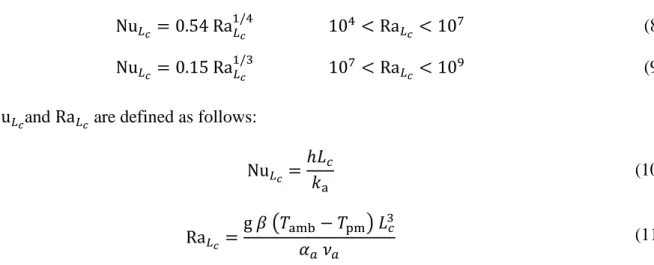
The heat transfer coefficient, ℎ, in Eq. (7) is calculated from the following correlations [23]: Nu𝐿𝑐 = 0.54 Ra𝐿𝑐 1/4 104 < Ra𝐿𝑐 < 10 7 (8) Nu𝐿𝑐 = 0.15 Ra𝐿 𝑐 1/3 107 < Ra𝐿𝑐 < 109 (9)
where Nu𝐿𝑐and Ra𝐿𝑐 are defined as follows:
Nu𝐿𝑐 = ℎ𝐿𝑐 𝑘a (10) Ra𝐿𝑐 = g 𝛽 (𝑇amb− 𝑇pm) 𝐿3𝑐 𝛼𝑎 𝜈𝑎 (11) where g is the gravitational constant, 𝑇pm is the mean temperature of the plate, 𝑘a is the air thermal conductivity (W/m.K), 𝛽 is the air coefficient of thermal expansion (K-1), 𝛼
𝑎 is the air thermal
diffusivity (m2/s), and 𝜈𝑎 the air kinematic viscosity (m2/s). The characteristic length, 𝐿𝑐, in the above equations is defined as:
𝐿𝑐 = 𝑊𝐿
2(𝑊 + 𝐿) (12)
The cooling capacity, of the panel 𝑄cool, is then estimated as
𝑄cool= (𝑞"rad+ 𝑞"conv) (𝑊𝐿) (13)
Table 1: Details of the operating conditions:
W×L (m2) 1.35 𝑉flow (m3) 5.64 × 10⁻⁴ 𝑇f,in (°C) 15 ṁ (kg/s) 0.004 𝑇amb (°C) 24 ɛ 0.9
- 8 -
In this section, the focus is on the serpentine flow arrangement for radiant cooling application. A typical panel consists of serpentine copper channels set on the upper side of an aluminum plate and covered with an insulation layer with the presence of small void in between filled with air (at rest), as depicted in Fig.1. The serpentine layout results from bending a single tube of fixed diameter at different positions to create a set of parallel segments equally spaced to guides the cooling water through a counter flow arrangement.
3.1 Numerical approach:
In order to create a model that should be computationally cost-effective, a pre-study was undertaken on a panel with an aspect ratio, W/L = 0.24. Two models were tested under the same thermal and flow conditions presented in Table 1. The problem was solved with a FEM software package [24]. First, a model accounting for the physical presence of the copper tube with the fluid flowing through was considered. This model was simplified afterward by removing the air cavity and replacing the tube by a thermally thin layer having the properties of copper. The geometries are displayed in Fig. 2 (a) and (b). The tube is made of copper with high thermal conductivity, 𝑘copp, and wall thickness, 𝛿,
significantly small. Therefore, the tube was modelled as a thin solid layer with the same properties. This way, only the tangential heat flux was accounted for, whereas the temperature gradient and heat flux across this thin layer are negligible. This assumption corresponds to a boundary surrounding the fluid, and the heat conduction for this layer is described from energy conservation [24]:
𝛁(− 𝛿 𝑘copp𝛁𝑇) = 𝑞"0 (14)
where 𝑞"0 is the heat flux received from the water domain.
For the complete model, a combination of structured and unstructured meshes was used. First, a free triangular element was created at one boundary, the inlet of the fluid for example, and then swept throughout the domain to create a structured shape. In the same manner, the upper surface of the plate was meshed using a free triangular element and then the mesh was swept to the lower surface.
- 9 -
Additionally, the air domain was meshed via unstructured mesh generated by the use of a free tetrahedral element. The total number of elements in this case was 12.1×10⁴. The same meshing procedure was applied for the simplified model after removing the air layer resulting in fewer total elements (3.52×10⁴).
To compare the performances of the two models, we observed the temperature distribution on the surface of the plate plotted as 𝐴𝑟(𝜃) where the non-dimensional temperature term, 𝜃, is given in Eq.
(15), and the surface ratio, 𝐴𝑟, is defined by Eq. (16).
𝜃 = 𝑇p− 𝑇f,in 𝑇amb− 𝑇f,in (15) 𝐴𝑟 = 𝐴𝜃 𝑊𝐿 (16)
where 𝐴𝜃 is the panel area at θ.
As can be seen in Fig. 3, the variation of 𝐴𝑟 for the simplified model duplicates that of the complete model. At any value of θ, the results from the two models are consistent. For example, when 𝜃 = 0.3 about 15% of the panel surface is at a temperature less than 17.7 °C. Additionally, the presence of the air in the model has no effect on the results. This can be attributed to the low thermal conductivity of air which acts as a thermal insulation. In the present investigation, therefore, the simplified model was used to simulate the cooling panel.
3.3 Mesh sensitivity study:
A mesh dependency assessment was conducted for the simplified version of the model shown in Fig. 2, which was used subsequently in this study. The impact of the mesh on the thermal and flow results was evaluated under the predetermined operating conditions mentioned earlier. Particularly, the discrepancy of the temperature distribution on the surface of the plate, the pressure drop and the
- 10 -
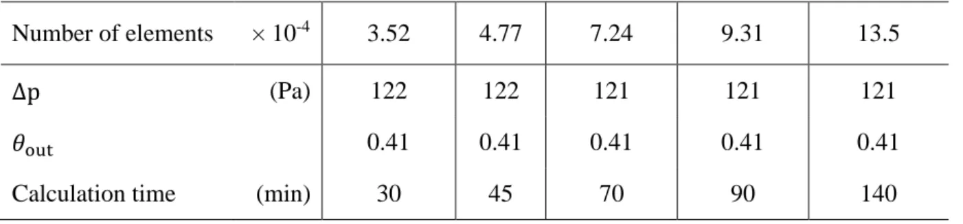
increase in fluid temperature across the panel were assessed. The size of the meshing elements on the fluid was altered from coarse to fine while maintaining the elements size for the plate unchanged. This way, the number of meshing elements for the plate was adapted to the variation of the fluid domain elements, so the total number of elements for the whole geometry changed from 3.52×10⁴ to 13.5×10⁴. Figure 4 depicts the effect of the mesh on the temperature distribution on the lower side of the plate and Table 2 below summarizes the results for the fluid side in addition to the calculation time.
The results suggest that the size of the mesh has no impact on the uniformity of the temperature distribution on the surface of the plate and the increase in fluid temperature. As far as the pressure drop behavior is concerned, the results are also consistent: with a coarse mesh, the model predicted a pressure drop higher of 1% than with the finest mesh. In conclusion, a converged solution could be obtained using a coarse mesh to reduce the computational resources without compromising the accuracy of the simulation.
Table 2: Effect of the mesh on the pressure drop and on the increase in fluid temperature across a cooling panel with W/L = 0.24 equipped with a serpentine tube
Number of elements × 10-4 3.52 4.77 7.24 9.31 13.5
∆p (Pa) 122 122 121 121 121
𝜃out 0.41 0.41 0.41 0.41 0.41
Calculation time (min) 30 45 70 90 140
3.1 Effect of the aspect ratio:
The effect of the aspect ratio, W/L, on the overall performance of the cooling panel was evaluated under the same conditions as in Table 1. As shown in Fig. 5, W/L varies from 0.24 to 2.79 while the
- 11 -
tube diameter, 𝐷, was constant accounting for the geometrical constraint set beforehand: fixed W×L and 𝑉flow. The spacing S between each U-turn is a constant. S is also the distance from the edge of the panel where the inlet and outlet are located.
Figure 6 portrays the influence of W/L on the surface temperature distribution. A steeper slope means more uniformity in temperature. Here it is obtained when W/L = 0.24. Yet, in the search for cooling at uniform panel temperature, a ratio W/L = 0.24 means also that overall the plate temperature is hotter than the higher aspect ratios. The slope of the curve then decreases when W/L increases, and becomes insensitive to further increases when W/L ≥ 1.05. This is illustrated in Fig.7 where the plate temperature map is drawn for all the aspect ratios.
Higher values of W/L enhance slightly the cooling capacity of the panel (as
𝜃out increases). The share of radiation heat transfer is above 60%. The enhancement in the cooling
performance, nevertheless, comes with greater pressure losses across the panel. The augmentation in pressure drop is linked to the increase in the number of bends over the total length of the serpentine tube, 𝑙tot. Accordingly, more pumping power, Ẇ , defined in Eq. (17), is required with higher W/L as shown in Fig. 8.
Ẇ =∆𝑝 ṁ
𝜌 (17)
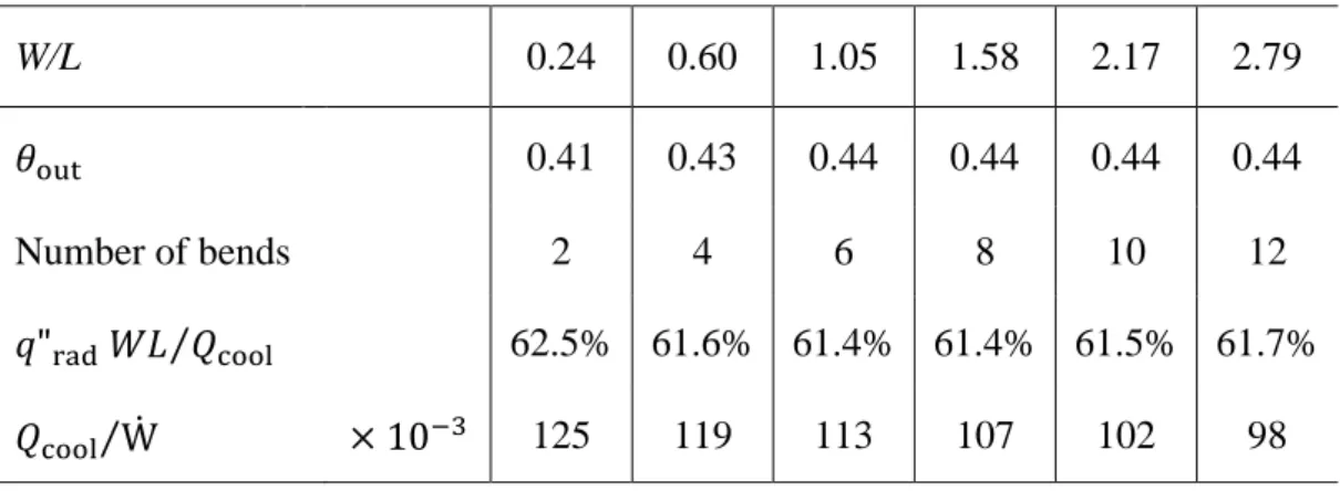
Table 3Erreur ! Référence non valide pour un signet. summarizes the effects of W/L on the mean results. Continuing to increase W/L beyond the almost square configuration does not add any more significant improvement, as demonstrated in Table 3: 𝜃out is almost constant independently of W/L,
- 12 -
Table 3: Effect of the W/L on the heat transfer performance for a suspended radiant cooling panel operating at Tamb W/L 0.24 0.60 1.05 1.58 2.17 2.79 𝜃out 0.41 0.43 0.44 0.44 0.44 0.44 Number of bends 2 4 6 8 10 12 𝑞"rad 𝑊𝐿 𝑄⁄ cool 62.5% 61.6% 61.4% 61.4% 61.5% 61.7% 𝑄cool⁄ Ẇ × 10−3 125 119 113 107 102 98
The current results display clearly that the serpentine flow arrangement does not result in a performing configuration. Thus, an efficient design of a radiant panel requires exploring different flow architectures in order to improve the overall performance.
4. Constructal design:
In this section, we examine new configurations giving the flow architecture the freedom to morph as encouraged by the Constructal law [25-29]. The canopy-to-canopy configuration is a special case of a more general feature: the dendritic design. In the canopy-to-canopy flow design, the cooling fluid enters in an inlet manifold that distributes the flow into multiple (equally spaced) tubes before being collected in an outlet manifold creating a parallel flow configuration. In this regard, a canopy-to-canopy design is a form of tree-shaped structure: here the tree trunk is represented by the mother tube of diameter D1, while the branches are of diameter D2. Two canopy-to-canopy flow passages are
considered in the present study to cool a panel with aspect ratios W/L= 0.24, 0.60, 1.05, 1.58 and 2.79. In the first canopy-to-canopy design, the tube diameter, 𝐷, remains constant throughout. In the second canopy-to-canopy design, the diameter in the inlet and outlet manifolds is 𝐷1, while for the distributed tubes the diameter is changed to 𝐷2. The canopy-to-canopy configurations are presented in Fig. 9.
- 13 -
The location S of the inlet and outlet of the flow network is identical to the one in the serpentine designs.
When moving from one single diameter to 2 different diameters, we started by calculating the Svelteness number of each structure so that the ratio 𝐷1⁄𝐷2 for minimum pressure losses could be
determined. The svelteness number (Sv), a new property defined by the Constructal law, relates the external and internal length scales of a flow system as follows [30]:
Sv =external length scale
internal length scale (18)
This property can be used as a criterion to facilitate the design procedure. Sv ≳ 10 means that the pressure drop across the system is dominated by the major losses associated with the straight flow passages and the local losses due to the presence of channels connections are negligible. Following the definition given in Eq. (18), we assumed that the external length scale is 𝐿path× W/L, where 𝐿path is the flow path from inlet to outlet. The internal length scale is 𝑉flow1/3. The minimum value obtained is Sv = 8 in the case of canopy-to-canopy design with W/L= 0.24.
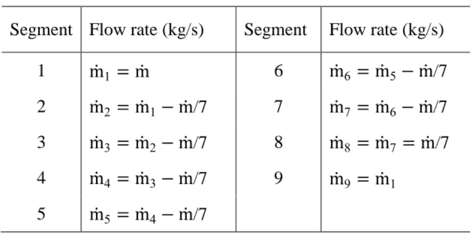
The diameter ratio corresponding to minimum overall pressure losses was therefore calculated in all the canopy-to-canopy configurations. To illustrate the methodology developed we present here the case of the canopy-to-canopy design with W/L= 1.05. There are 7 channels in parallel separated by a constant distance S. We assumed that the mass flow rate, ṁ, splits equally into the 7 ducts, ṁ/7. For a laminar flow with a flow rate of ṁ in a circular channel of diameter 𝐷, the pressure drop, ∆𝑝, due to friction along a flow path is proportional to ṁ 𝐷⁄ 4 [31].
To derive the ∆𝑝 equation, we considered the pathway connecting the lines 1 to 9 as showing in Fig.9. The flow rate distribution in all the segments along this path is presented in Table 4. We have from the inlet to outlet:
- 14 - ∆𝑝~(ṁ1 + ṁ2+ ṁ3+ ṁ4+ ṁ5+ ṁ6 + ṁ7+ ṁ9) S 𝐷14 +ṁ8(𝑊 − 2 S) 7 𝐷24 (19)
Substituting the corresponding flow rates from Table 4, Eq. (19) was simplified to:
∆𝑝 ṁ ~ 5 S 𝐷14 + (𝑊 − 2 S) 7 𝐷24 (20)
Table 4: Flow rate distribution along 𝐿path for the canopy-to-canopy design with W/L = 1.05.
Segment Flow rate (kg/s) Segment Flow rate (kg/s) 1 ṁ1 = ṁ 6 ṁ6 = ṁ5− ṁ/7
2 ṁ2 = ṁ1 − ṁ/7 7 ṁ7 = ṁ6− ṁ/7
3 ṁ3 = ṁ2 − ṁ/7 8 ṁ8 = ṁ7 = ṁ/7
4 ṁ4 = ṁ3 − ṁ/7 9 ṁ9 = ṁ1
5 ṁ5 = ṁ4 − ṁ/7
The flow volume, 𝑉flow, remains fixed. In this configuration, the fluid occupies the inlet and outlet
manifolds in addition to the seven parallel lines. The total volume allocated to the flow for this flow arrangement is given by Eq. (21).
𝑉flow~2 (𝐿 − S) 𝐷12+ 7 (𝑊 − 2 S) 𝐷22 (21)
In the search for minimum losses while the flow volume is constant, we invoke the method of the Lagrange multipliers, and obtain
𝐷1 𝐷2 = [ 245 S 2 (𝐿 − S)] 1/6 (22)
The numerical modeling of the different cases was performed following the procedure described in section 3. The same care was applied to the mesh construction.
- 15 -
We show in Fig. 10 the flow distribution in the parallel channels of the 3 canopy-to-canopy designs. Figure 10 (a) present the case of W/L = 0.24, while the mass flow rate distribution in the parallel ducts is given in Fig. 10 (b) for W/L = 1.05 and in Fig. 10 (c) when W/L = 2.79. Whatever the panel aspect ratio, working with one single diameter leads to a flow mal distribution which yet tends to decrease with higher W/L ratios. Overall the distribution of the mass flow rate along the parallel channels follows a U shape with the highest mass flow rate located in the parallel duct the closest to the outlet. When choosing a two-diameter configuration, the mass flow rate distribution in the parallel channels is smoothen whatever the panel aspect ratio, which is in line with the Constructal viewpoint of distribution of imperfections. Even though the thermodynamic imperfections cannot be removed, they can be distributed and reduced by discovering the geometrical features of the flow configuration. In terms of temperature distribution, the impact of the one-diameter or two-diameter configuration is almost non noticeable as shown in Fig. 11. Furthermore, Fig. 12 illustrates the temperature map in the case when the network is made of 2 different diameters leading to minimum pressure losses.
The overall pressure losses were used to calculate the pumping power by means of Eq. (17). The cooling capacity was also determined. The systems efficiency is presented in Fig. 13 in terms of cooling capacity/pumping power ratio as a function of the aspect ratio W/L. Whatever the W/L value, any canopy-to-canopy design outperforms the serpentine configurations. Even better when playing with the diameter ratio, the case W/L = 1.05 clearly leads to better performance than any other architecture. Compared to the equivalent designs with 2-diameters pipe, this configuration is the one for which the flow path is the shortest compared to the cases W/L = 0.24 and 2.79. This result calls for more compactness in the design of radiant panels.
A summary of the results is given in Fig. 14 where the non-dimensional cooling capacity is plotted as a function of the non-dimensional pumping power for all the cases approached in this work. On this map of global performance, the best designs are the ones heading to the top left corner of the
- 16 -
graph. Playing with the panel aspect ratio for the serpentine configuration allows to increase the heat transfer performance as seen earlier. Yet this result is obtained at the expense of the fluid mechanics performance. Only a drastic change in the drawing, serpentine to dendritic design, allows to move on the map in the direction of better combined performances. On the path towards high cooling capacity and low pumping power together, Fig. 14 proves that more degree of freedom – here 2-diameter designs – is the way to proceed.
Conclusion
We showed in this work that the efficiency of radiant cooling panels for building applications can be improved. Starting from a classical serpentine flow architecture design, we demonstrated how the panel aspect ratio should evolve in order to provide better panel temperature distribution and smaller pumping power.
Yet, moving toward better performances for the same conditions (mass flow rate, flow volume) can only be achieved through a dramatic change in the design of the flow architecture. A canopy-to-canopy design constitutes and answer to this challenge. As demonstrated, this dendritic architecture, given enough freedom to morph (here, in terms of diameter ratio) allows a significant improvement in the cooling panel performance, with more cooling capacity and less pumping power. In addition, we showed that the morphing of the panel itself toward more compactness is also a way to increase the ratio of cooling capacity/pumping power.
Acknowledgements
- 17 - REFERENCES
[1] A. Bejan, Street network theory of organization in nature, J. Adv. Transp. 30 (1996) 85–107. [2] A. Bejan, S. Lorente, Design with Constructal Theory, John Wiley & Sons, Hoboken, N.J., 2008.
[3] A. Bejan, Evolution in thermodynamics, Applied Physics Reviews. 4 (2017) 011305. [4] L.A.O. Rocha, S. Lorente, A. Bejan, Constructal design for cooling a disc-shaped area by conduction, International Journal of Heat and Mass Transfer. 45 (2002) 1643–1652.
[5] G. Lorenzini, C. Biserni, L.A.O. Rocha, Constructal design of X-shaped conductive pathways for cooling a heat-generating body, International Journal of Heat and Mass Transfer. 58 (2013) 513–520.
[6] G. Lorenzini, E.X. Barreto, C.C. Beckel, P.S. Schneider, L.A. Isoldi, E.D. dos Santos, L.A.O. Rocha, Constructal design of I-shaped high conductive pathway for cooling a heat-generating medium considering the thermal contact resistance, International Journal of Heat and Mass Transfer. 93 (2016) 770–777.
[7] S. Lorente, A. Bejan, J.L. Niu, Phase change heat storage in an enclosure with vertical pipe in the center, International Journal of Heat and Mass Transfer. 72 (2014) 329–335.
[8] S. Lorente, A. Bejan, J.L. Niu, Constructal design of latent thermal energy storage with vertical spiral heaters, International Journal of Heat and Mass Transfer. 81 (2015) 283–288. [9] C. Bai, L.Q.Wang, Two nanofluid configurations for heat conduction systems: performance
comparison, International Journal of Heat and Mass Transfer. 66 (2013) 632–641.
[10] A. Almerbati, S. Lorente, A. Bejan, The evolutionary design of cooling a plate with one stream, International Journal of Heat and Mass Transfer. 116 (2018) 9–15.
[11] J. Miriel, L. Serres, A. Trombe, Radiant ceiling panel heating–cooling systems: experimental and simulated study of the performances, thermal comfort and energy consumptions, Applied Thermal Engineering. 22 (2002) 1861–1873.
- 18 -
[12] K.-N. Rhee, K.W. Kim, A 50 year review of basic and applied research in radiant heating and cooling systems for the built environment, Building and Environment. 91 (2015) 166–190. [13] K.-N. Rhee, B.W. Olesen, K.W. Kim, Ten questions about radiant heating and cooling
systems, Building and Environment. 112 (2017) 367–381.
[14] T. Imanari, T. Omori, K. Bogaki, Thermal comfort and energy consumption of the radiant ceiling panel system.: Comparison with the conventional all-air system, Energy and Buildings. 30 (1999) 167–175.
[15] H.E. Feustel, C. Stetiu, Hydronic radiant cooling — preliminary assessment, Energy and Buildings. 22 (1995) 193–205.
[16] ASHRAE Handbook—HVAC Systems and Equipment, Chapter 6: Panel heating and cooling, ASHRAE, Atlanta, GA, 2012.
[17] N. Fonseca, Experimental study of thermal condition in a room with hydronic cooling radiant surfaces, International Journal of Refrigeration. 34 (2011) 686–695.
[18] M. Tye-Gingras, L. Gosselin, Investigation on heat transfer modeling assumptions for radiant panels with serpentine layout, Energy and Buildings. 43 (2011) 1598–1608.
[19] A. Laouadi, Development of a radiant heating and cooling model for building energy simulation software, Building and Environment. 39 (2004) 421–431.
[20] H. Tang, X.-H. Liu, H. Li, Y. Zhou, Y. Jiang, Study on the reduction of condensation risks on the radiant cooling ceiling with superhydrophobic treatment, Building and Environment. 100 (2016) 135–144.
[21] B. Ning, Y. Chen, H. Liu, S. Zhang, Cooling capacity improvement for a radiant ceiling panel with uniform surface temperature distribution, Building and Environment. 102 (2016) 64–72. [22] N. Aste, C. del Pero, F. Leonforte, Water flat plate PV–thermal collectors: A review, Solar
Energy. 102 (2014) 98–115.
[23] A. Bejan, Convection heat transfer, 3rd ed, Wiley, Hoboken, N.J, 2004.
- 19 -
[25] S. Kim, S. Lorente, A. Bejan, Vascularized materials: Tree-shaped flow architectures matched canopy to canopy, Journal of Applied Physics. 100 (2006) 063525.
[26] S. Kim, S. Lorente, A. Bejan, Vascularized materials with heating from one side and coolant forced from the other side, International Journal of Heat and Mass Transfer. 50 (2007) 3498– 3506.
[27] J. Lee, S. Kim, S. Lorente, A. Bejan, Vascularization with trees matched canopy to canopy: Diagonal channels with multiple sizes, International Journal of Heat and Mass Transfer. 51 (2008) 2029–2040.
[28] K.-M. Wang, S. Lorente, A. Bejan, Vascular materials cooled with grids and radial channels, International Journal of Heat and Mass Transfer. 52 (2009) 1230–1239.
[29] J. Lee, S. Lorente, A. Bejan, M. Kim, Vascular structures with flow uniformity and small resistance, International Journal of Heat and Mass Transfer. 52 (2009) 1761–1768.
[30] S. Lorente, A. Bejan, Svelteness, freedom to morph, and constructal multi-scale flow structures, International Journal of Thermal Sciences. 44 (2005) 1123–1130.
[31] H. Ghaedamini, M.R. Salimpour, A.S. Mujumdar, The effect of svelteness on the bifurcation angles role in pressure drop and flow uniformity of tree-shaped microchannels, Applied Thermal Engineering. 31 (2011) 708–716.
- 20 - Figure 1 ṁ 𝑇f,in ṁ 𝑞"rad+ 𝑞"conv 𝑇amb L W
- 21 - Air Water Copper tube Aluminum plate (a) Water Thin layer Aluminum plate (b) Figure 2
- 22 -
- 23 -
- 24 -
- 25 -
- 26 -
- 27 -
- 28 -
- 29 -
(a)
(b)
- 30 -
Figure 10
- 31 -
- 32 -
- 33 -
- 34 - Figure captions
Figure 1 Sketch of a radiant cooling panel.
Figure 2 (a) complete model and (b) simplified model
Figure 3 Temperature distribution on the surface of the radiant cooling panel (W/L = 0.24): complete model vs simplified model.
Figure 4 Effect of the mesh on the temperature distribution on the surface of the radiant cooling panel (W/L = 0.24).
Figure 5 Panel with different aspect ratio, serpentine flow architecture.
Figure 6 Effect of aspect ratio on the temperature distribution on the surface of the radiant cooling panel with serpentine flow patterns.
Figure 7 Temperature map for serpentine design.
Figure 8 Effect of the aspect ratio on the pumping power for serpentine design. Figure 9 Canopy-to-canopy flow architecture.
Figure 10 Mass flow rate distribution in the parallel channels of the canopy-to-canopy design for W/L = 0.24, 1.05 and 2.79.
Figure 11 Temperature distribution for the canopy-to-canopy design (two-diameter case). Figure 12 Temperature map for the canopy-to-canopy.
Figure 13 Cooling capacity/pumping power ratio as a function of the panel aspect ratio W/L. Figure 14 Overall performance map.