Publisher’s version / Version de l'éditeur:
Vous avez des questions? Nous pouvons vous aider. Pour communiquer directement avec un auteur, consultez la
première page de la revue dans laquelle son article a été publié afin de trouver ses coordonnées. Si vous n’arrivez pas à les repérer, communiquez avec nous à PublicationsArchive-ArchivesPublications@nrc-cnrc.gc.ca.
Questions? Contact the NRC Publications Archive team at
PublicationsArchive-ArchivesPublications@nrc-cnrc.gc.ca. If you wish to email the authors directly, please see the first page of the publication for their contact information.
https://publications-cnrc.canada.ca/fra/droits
L’accès à ce site Web et l’utilisation de son contenu sont assujettis aux conditions présentées dans le site LISEZ CES CONDITIONS ATTENTIVEMENT AVANT D’UTILISER CE SITE WEB.
Combustion Canada 2003 [Proceedings], pp. 1-12, 2003-09-01
READ THESE TERMS AND CONDITIONS CAREFULLY BEFORE USING THIS WEBSITE. https://nrc-publications.canada.ca/eng/copyright
NRC Publications Archive Record / Notice des Archives des publications du CNRC :
https://nrc-publications.canada.ca/eng/view/object/?id=3fa0b94d-e1aa-496d-96c7-302075de5799 https://publications-cnrc.canada.ca/fra/voir/objet/?id=3fa0b94d-e1aa-496d-96c7-302075de5799
NRC Publications Archive
Archives des publications du CNRC
This publication could be one of several versions: author’s original, accepted manuscript or the publisher’s version. / La version de cette publication peut être l’une des suivantes : la version prépublication de l’auteur, la version acceptée du manuscrit ou la version de l’éditeur.
Access and use of this website and the material on it are subject to the Terms and Conditions set forth at
Study of combustion noise reduction in a kerosene burner : investigation of nozzle and pre-heating chamber flow-field
Jiang, L. Y.; Yimer, I.; Campbell, I.; Liu, Z. G.; Liu, Z. S.; Huang, C.; Fisher, C.; Schwartzman, A.; Zhang, J.
Study of combustion noise reduction in a kerosene burner – investigation of nozzle and pre-heating chamber flow-field
Jiang, L.Y.; Yimer, I.; Campbell, I.; Liu, Z.; Liu, Z.S.; Huang, C.; Fisher, C.; Schwartzman, A.; Zhang, J.
NRCC-46729
A version of this document is published in / Une version de ce document se trouve dans : Combustion Canada 2003, Vancouver, B.C., Sept. 22-25, 2003, pp. 1-12
STUDY OF COMBUSTION NOISE REDUCTION IN A KEROSENE BURNER
--- INVESTIGATION OF NOZZLE AND PRE-HEATING CHAMBER FLOW-FIELD
L.Y. Jiang∗, I. Yimer*, I. Campbell*, Z. Liu+, Z.S. Liu++ and C. Huang++
National Research Council Canada, Ottawa, Canada, K1A 0R6, Telephone: 613-993-9235, Email: leiyong.jiang@nrc.ca (contact person)
C. Fisher∗∗, A. Schwartzman∗∗∗, and J. Zhang∗∗∗
Teleflex [Canada] Ltd., 3831 No. 6 Road, Richmond, BC, Canada, V6V 1P6 Telephone: 604-270-6899, Fax: 604-270-7172
ABSTRACT
The combustion noise generated in a small burner was successfully reduced by installing a short tube inside the pre-heating chamber of the burner. To understand the noise reduction mechanism, the flow-field of the nozzle and pre-heating chamber with and without the inner tube was numerically studied in conjunction with some experimental measurements. The fuel spray characteristics obtained from Phase Doppler Particle Analyser (PDPA) measurements were used to define initial conditions of the spray discrete phase. Couplings between the continuous and discrete phases, as well as the turbulent stochastic effect were modelled. It is found that the installation of an inner tube in the pre-heating chamber modifies the flow-field, fuel spray trajectories, and reduces local velocities and turbulent strength. These contribute to the reduction in combustion noise. Most of all, the considerable modification of the fuel spray distribution in the pre-heating chamber plays a major role in the combustion noise reduction of the burner. In addition, the numerical results also show that the flow-field in the vicinity of the nozzle is very complicated and practically identical for both cases. A strong toroidal vortex is formed in the centre region of the nozzle, and a high velocity swirling airflow is observed outside the core region.
INTRODUCTION
Today, combustion system design engineers face many new challenges largely due to environmental concerns and competitive market. One of the concerns is the noise emission,
∗ Research Officer, Institute for Aerospace Research + Research Officer, Institute for Research in Construction
++ Research Officer, Institute for Fuel Cell Innovation, Vancouver ∗∗ Engineering Manager, Teleflex Canada
which deteriorates the working environment and sometimes causes devastating structural damage [1, 2].
In an attempt to reduce the combustion noise of a burner, schematically shown in Fig. 1, a series of experimental studies were conducted at Institute for Fuel Cell Innovation (Vancouver), National Research Council Canada (NRC) [3-5]. The effectiveness of several techniques for reducing combustion noise from the burner were investigated, including inserting various short tubes over the exhaust holes, placing different types of flame holders inside the combustion chamber, attaching nozzle wraps around the fuel nozzle, as well as installing cylindrical tubes in the pre-heating chamber. It was found that installing a short cylindrical tube in the pre-heating chamber is the most promising solution to alleviate the noise problem at all three firing rates, particularly at the low firing rate [3-5].
In order to better understand the noise reduction mechanism of this geometric modification and provide detailed flow-field information, both numerical and experimental investigations of the burner are underway at Institute for Aerospace Research, NRC. The numerical studies include simulations of the fluid-fields of the fuel nozzle, pre-heating chamber and combustion chamber of the burner with and without combustion. In parallel to the numerical investigation, flow visualization, fuel nozzle spray characterization, as well as temperature and velocity measurements are being or will be undertaken.
Considering that the burner modification was made in the pre-heating chamber only, the flow-field of the nozzle and pre-heating chamber is of main interest in the present paper. Furthermore, as a first step of the study, the numerical results without combustion are presented and discussed. In addition to the numerical analyses, the PDPA measurements and flow visualization of the fuel spray are also briefly reported in the paper. The experimental data obtained from the PDPA measurements were used to define initial spray conditions in the simulations.
THE BURNER AND SPRAY MEASUREMENT The Burner
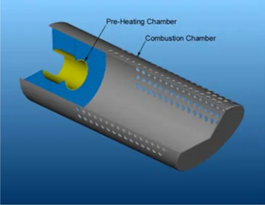
Figure 1 gives a three-quarter view of the main body of the burner. It consists of a pre-heating chamber and a combustion chamber. There are a large number of holes in the wall of the
Fig. 2 Schematic diagram of the inner tube Fig. 1. Schematic of the burner chamber
combustion chamber to vent combustion products. An air-assist fuel nozzle, not shown in the figure, is located 18 mm upstream of the pre-heating chamber. During operation, kerosene liquid fuel is siphoned out from a liquid fuel tank by high velocity compressed air. The fuel spray has a nominal spray angle of 40 degrees at design condition. The high velocity mixture of air and fuel spray entrains substantial amount of ambient air over a short distance, then enters the pre-heating chamber, and finally into the combustion chamber. The burner has three firing rates, 5.3 kW, 11.5 kW and 17.3 kW. The modification on the original burner is schematically shown in Fig. 2, where an inner tube is installed in the pre-heating chamber.
Nozzle Spray PDPA Measurement
The PDPA system in the Spray Laboratory at Gas Turbine Environmental Research Centre (GTERC), NRC was used to measure the fuel droplet characteristics of the burner nozzle at a number of downstream cross-sections. Figure 3 illustrates the experimental set up. The spray test rig was confined in a large octagonal enclosure to prevent fuel from spilling. A 2-D
transmitter (two-colour) of the PDPA was placed normal to the nozzle axis and formed a measurement volume at the focal point. The light scattered from droplets in the measurement volume was collected in the forward
off-axis direction, at an angle of 30o
from the optical axis of the system, via a receiver. Doppler signals from three detectors of the receiver were processed to provide information to calculate the size and two velocity components for the same droplet. The droplet size was determined by the phase shift of the Doppler signals, while the droplet velocity components were calculated from the Doppler frequencies. By moving the test rig in the X and Y direction, three velocity components of droplets were obtained. At each radial location, 5000 realizations were used to determine mean and other statistical properties for droplet size and velocity components.
30o Y X Z Ur Uz Uθ Uz
Fig. 3 Schematic diagram of the PDPA measurement
In addition to the PDPA measurements, the flow visualisation of the fuel spray was also conducted by using a laser sheet and a digital CCD camera. The details of the experimental set-up, together with the comprehensive measurements and the corresponding data reduction will be published separately.
NUMERICAL SIMULATION Computational Domain
The computational domain covered the air and fuel inlets of the nozzle up to the exit of the pre-heating chamber. Owing to the geometric symmetry, the computational domain was reduced
to a 60-degree sector, and consequently the mesh size and computational time were greatly reduced.
Fig. 4 60o sector of the nozzle and pre-heating
chamber inner tube open surfaces
pre-heating chamber wall
Fig. 5 Close-up view of the 60o sector fuel-inlet
air-inlet
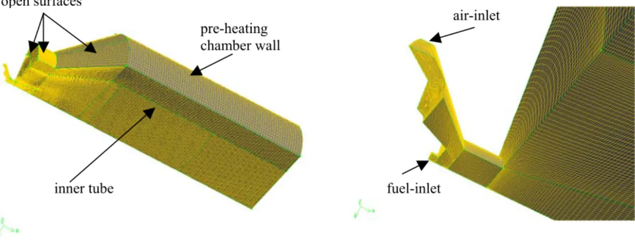
Figure 4 shows the hybrid mesh describing the 60o sector of the nozzle and pre-heating
chamber for the modified geometry. The inner tube, pre-heating chamber wall and all surfaces open to the ambient are shown in Fig. 4. Figure 5 gives a close-up view of the mesh for the air and fuel inlets of the nozzle. The fuel inlet has a diameter of 0.45 mm located at the centre of the nozzle. One air-inlet is shown in Figure 5, which is a part of a cylindrical surface. The nozzle exit diameter is 1.8 mm.
A total number of 123,309 elements were used for both cases with and without the inner tube. To resolve the tiny nozzle flow, a mesh interval size of 0.07 mm was applied, and fine grids were also laid along the nozzle jet flow path. The grids gradually became coarse in the axial and radial direction. To check mesh independence, another mesh with 490,793 elements
was generated with an interval size of 0.03 mm in the nozzle region. The Y+ values were in the
range of 1-15 at the nozzle wall for the coarse mesh case and in the range of 1-10 for the fine
mesh. A Y+ value about 1 was maintained at the walls of the inner tube and pre-heating chamber
for both cases. The averaged equal-angle skewness was 0.19 and the maximum skewness was less than 0.8. The differences in numerical results between the fine and coarse meshes were negligibly small. Only trivial discrepancies in the tiny regions within the nozzle were observed. The maximum velocity magnitude difference was less than 1 m/s, 0.5% in percentage.
Physical Modeling
Three-dimensional, steady, compressible, turbulent, two-phase flows were considered in the analysis. The governing Reynolds averaged conservation equations for mass, momentum and energy of the continuous phase are not reproduced here because they can be readily found in any classic literatures, such as Reference 6. To close the above equations, the realizable k-ε turbulence model proposed by Shih et al. [7] was used to calculate turbulent transport properties. This model has shown advantages in flows with separations and recirculations, as well as jet spread rate predictions [7, 8]. It is consistent with the physics on the Reynolds stresses in
turbulent flows (positive turbulent normal stresses and Schwarz inequality for shear stresses). According to this model, the turbulent viscosity is expressed as,
ε ρ
µ Cµk2 /
t = (1)
Unlike the standard and renormalization group (RNG) k-ε turbulence models, Cµ in Eq. (1) is no
longer a constant, but a function of the mean strain and rotation rates, and the turbulence field (k and ε). It can be expressed as
ε Ω Ω µ ij ij ij ij S 0 S S k A A 1 C + + = (2)
where Sij and Ωij are the mean strain and rotation rates, A0 = 4.04, and AS = 6cosφ with φ
obtained by the following expression,
(
)
= − 2 / 3 ij ij ki jk ij 1 S S S S S 6 cos 3 1 φ (3)The quantities of the turbulent kinetic energy, k, and dissipation rate, ε, are found from the following pair of equations,
( )
(
)
k M i t t i i i Y G x k x ku x k t + − − ∂ ∂ + ∂ ∂ = ∂ ∂ + ∂ ∂ ρε σ µ µ ρ ρ (4)( )
(
)
νε ε ρ ε ρ ε σ µ µ ε ρ ρε ε + − + ∂ ∂ + ∂ ∂ = ∂ ∂ + ∂ ∂ k C S C x x u x t 2 2 1 i t i i i (5)In Eq. (4), Gk =2µtSijSij is the turbulence production term, Y accounts for the
compressibility effect where “a” is the speed of sound, and σ
2 M =2ρεk/a k = 1.0. In Eq. (5), S = 2SijSij , =max 5 C1 k + S / k S , 43 . 0 ε
ε , C2 = 1.9, and σε = 1.2. It is obvious that the turbulence
dissipation equation is quite different from the standard and RNG k-ε models.
As mentioned earlier, the Y+ values at the nozzle wall were in a range of 1-15 and about
one at the inner tube and pre-heating chamber walls. To adequately solve these wall boundaries, an enhanced wall boundary treatment, suggested by Kader [9], was applied, where the traditional two-layer zonal model is enhanced by smoothly blending the viscous sub-layer and fully turbulent regions.
Discrete fuel droplets were simulated in a Lagrangian frame of reference. The couplings between the continuous and discrete phases, as well as the impact on both phases were included. In the present study, the droplet volume flow rate is only 0.17% of the airflow rate, and the droplets, with the same static temperature as the air, were injected into the flow-field far enough downstream of the nozzle. Therefore, dilute spherical inert droplets were assumed in the analyses, i.e., no droplet collision and break-up were considered.
Boundary Conditions
The effect of the inner tube on the noise reduction is most notable at the low firing rate [3-5], and therefore the flow parameters at the low firing rate were used in the analyses. The air
mass flow rate for the single air-inlet was 2.34×10⁻⁵ kg/s corresponding to 7×10⁻³ N m3/s. Notice
that the fuel volume flow rate is only 12.2 ml/min, 0.17% of the airflow volume rate. To approximate the effect of the fuel on the flow field, an additional airflow with the same volume flow rate as the liquid fuel was introduced into the fuel inlet. A turbulence intensity of 10% and hydraulic diameters of the fuel and air inlets were used to estimate inlet turbulence kinetic energy and dissipation rate.
Rotational periodic boundary conditions were specified for the cut surfaces of the 60o
sector. The atmospheric pressure was defined at the air entrainment surfaces and pre-heating chamber exit. The latter was justified by the preliminary numerical study of the whole burner flow-field without combustion. The deviation of pressure at the pre-heating chamber exit from the atmospheric pressure was extremely small (less than a few pascals). For the original geometry, the insert tube in the pre-heating chamber was treated as an interior surface. No-slip and “trap” boundary conditions were defined at the walls of the pre-heating chamber and inner tube if applicable. That is, the flow is stationary at the wall, and the fuel droplets terminate when they hit the wall.
The PDPA spray measurements were made at a number of cross-sections downstream of the nozzle. The droplet characteristics at 11 mm (24.4 nozzle diameters) downstream of the nozzle exit were used to define the initial spray conditions in the simulations. The profiles of mean Sauter droplet diameters (D32), mean velocity components and volume flow rates along the radial direction were divided into ten regions as shown in the following table,
Group Region (mm) D32 (µm) V/ΣVi UZ UY UX
1 0 – 4 18 6 % 9.7 0.7 -2.3 2 4 – 6 26 14 % 5.6 1.6 -1.2 3 6 – 7 30 12 % 4.2 2.1 -0.4 4 7 – 8 35 16 % 4.0 2.4 -0.24 5 8 – 9 37 14 % 3.9 2.7 -0.2 6 9 – 10 38 12 % 3.7 3.1 -0.12 7 10 – 11 40 8 % 3.3 3.0 -0.1 8 11 – 12 41 6 % 2.7 2.8 -0.06 9 12 – 14 42 8 % 1.2 2.3 -0.02 10 14 – 16 41 4 % 0.7 1.0 0
The droplet parameters at the middle of each region were used to define the initial injection conditions for that region. As shown in Fig. 6, the fuel droplet streams were released from ten arc lines at the cross-section, 11 mm downstream of the nozzle. There were a total number of 67 droplet streams. Each stream represented 2 % of the fuel volume rate in Groups 1 to 6, 1 % in Groups 7 to 9 and 0.5 % in the last group. To account for the turbulence stochastic effect on droplet trajectories, each droplet stream contained 60 droplets in Groups 1 to 6, 30 droplets in Groups 7 to 9, and 15 in the last group. The total number of droplets released during each
discrete phase iteration was 3000. The trajectories of individual particles were obtained with the instantaneous fluid velocity along the particle path during the integration.
Solution Method
A segregated solver from a commercial code, Fluent, was used to resolve the flow-field with the second-order accuracy scheme. Double precision was used for all the simulations since the ratio of
maximum cell volume to the minimum was over 105.
The flow-field was solved first without discrete droplet injections, and then the continuous and discrete phases were solved alternatively until convergence. The normalized residual was less than
7×10⁻⁷ for the velocity components and 5×10⁻⁵ for
the turbulence quantities. For the continuity
equation, the residual reached 1.1×10⁻⁶ normalized
by the largest absolute residual in the first five iterations. The solutions were well converged, and the monitored axial velocity in the shear layer about 4 mm downstream of the nozzle remained unchanged in the first five digits. A LINUX PC server with two Pentium 2.8-GH CPUs and 4 GB RAM was used in the numerical analysis.
Fig. 6 Injection locations of fuel streams
RESULTS AND DISCUSSION
Flow-Field with and without the Inner Tube
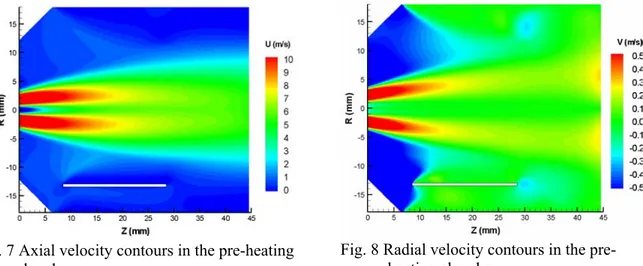
In Figs. 7 and 8, the axial and radial velocity contours with the inner tube are compared with those without the inner tube in the pre-heating chamber. In these figures and some of the
following figures, the lower halves represent the case with the inner tube, while the upper halves stand for the case without the inner tube. The white thick line indicates where the inner tube is located. The flow feature and pattern are similar in both cases. However, differences are
Fig. 7 Axial velocity contours in the pre-heating chamber
Fig. 8 Radial velocity contours in the pre-heating chamber
observed. Unlike the original design case, the axial velocity around the inner tube remains lower in the modified case, as shown in Fig. 7. The flow entrainment, indicated by the inward (negative) radial velocity, induced by the nozzle jet seems restricted due to the presence of the inner tube (see Fig. 8).
Figure 9 shows the axial velocity contours at the middle cross-section of the inner tube. The flow velocities in the core regions are close to each other although the core region is slightly
wider for the case with the inner tube. Away from the core, the velocity gradually decreases to zero at the inner tube wall for the case with the inner tube. For the case without the inner tube, the axial velocity in the corresponding regions is more uniform with slightly higher magnitude. The ratios of turbulence viscosity versus laminar viscosity are illustrated in Fig. 10 for both flows. The turbulence level remains lower near the inner tube for the case with the inner tube, and it is also true along the annular main flow path, indicated by the red and orange colour.
Fig. 9 Axial velocity contours at the middle
cross-section of the inner tube Fig. 10 Turbulent and laminar viscosity ratios
The above figures indicate that placing a short inner tube inside the pre-heating chamber modifies the flow-field, and reduces local velocities and turbulent strength. These may contribute to the noise reduction of the burner. The reduction in local velocities and turbulence strength in the pre-heating chamber may delay the fuel atomization and/or evaporation process in these local regions. Consequently, the combustion intensity in the pre-heating chamber may be reduced and the diffusion flame may become relatively stable.
Fuel Spray Distributions
The fuel spray discharged from the nozzle was visualized with a laser sheet at all three firing rates. Figure 11 shows the spray flow-field at the low firing rate, obtained with an exposure time of 800 µs, while Fig. 12 presents the spray flow-field at the high firing rate with the same exposure time. At the high firing rate or design condition, the airflow rate was 14.9 SLPM and the fuel flow rate was 25.8 ml/min. The spray angle at the low firing rate is about 80 degrees, obviously larger than that (about 65 degrees) at the high firing rate. The spray angle at the low firing rate nearly doubles the nominal spray angle (40 degrees) of the nozzle. The reasons are two-fold. First, the spray angle was measured according to the spray envelope in this paper, which is unlikely the same as that used by the manufacturer. Secondly, the airflow rate is
low, only about half of the design condition. The change in spray angle has significant impact on fuel distribution as well as subsequent combustion.
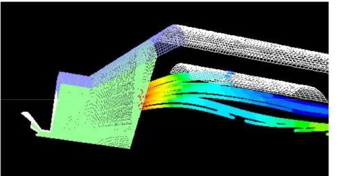
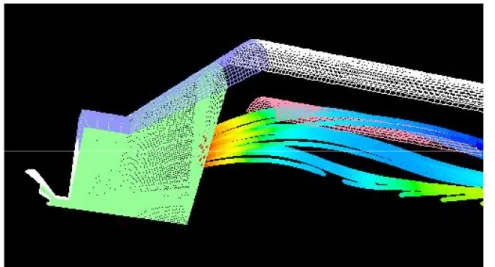
The fuel droplet trajectories, coupled with the airflow field and the turbulent stochastic effect, were simulated for both flows with and without the inner tube. Figure 13 illustrates the mean droplet trajectories for Groups 3 to 5 in the case with the inner tube. Since the effect of the inner tube on the spray field is of main interest, the droplet trajectories for Groups 3 to 5 are displayed here for clarity. For the same reason, only the mean droplet trajectories, instead of random trajectories, are drawn in the plot. In Fig. 13, the white colour represents the walls of the inner tube, pre-heating chamber and nozzle, the light blue represents the open surfaces, and the light green is for the interior surfaces. The broken trajectory lines indicate where the droplets have moved into other sectors of the flow-field. Note that the volume flow fluxes of Groups 3 to 5 are higher than any other groups (see the above table). These three groups are made of 21 droplet streams. Seven among them, about 14% of the total fuel, are trapped by the inner tube wall and the rest pass through the computational domain. The total volume rate fraction through the inner tube is about 62 %, from Group 1 to Group 5.
Fig. 11 Fuel spray at the low firing rate
1 cm
Fig. 12 Fuel spray at the high firing rate
1 cm
Fig. 13 Mean droplet trajectories for Groups 3-5 with the inner tube
Figure 14 shows the mean droplet trajectories without the inner tube. The pink surface is an interior surface where the inner tube is located in the modified design case. Figure 14 clearly shows that the seven droplet streams from Group 5 penetrate the pink interior surface. As a results, the fuel volume rate fraction passing through the region enclosed by the pink surface is
about 48 %, 14 % less than the case with the inner tube. This means that more fuel flows in the annular region between the pink surface and the pre-heating chamber wall for the case without the inner tube.
These results suggest that the effect of the inner tube on the fuel spray distribution plays a crucial role in the noise reduction of the burner at the low firing rate. The redistribution of the fuel spray in the pre-heating chamber will result in the rearrangement of combustion in the burner. It is anticipated that the fuel droplets trapped by the inner tube wall will be evaporated or
form large droplets, depending on the local temperature of the inner tube wall during operation. In either case, the temperature at the inner tube wall will remain low during operation. This will prevent combustion occurring in the pre-heating chamber and push the flame region downstream into the combustion chamber, as observed in References [3 – 5]. The flame will be anchored by the recirculation zone, located in the geometric sudden expansion region, downstream of the pre-heating chamber (Fig. 1) as observed at the high firing rate. As a result, the unstable combustion at the low firing rate will be transferred to a stable one. The change in combustion arrangement will cause variations of the burner acoustic characteristics, for example the distance between the nozzle and the flame will be increased. Liu, et al. [4] have observed and measured the noise spectra with and without the inner tube, and pointed out that one component in the noise spectra, corresponding to one self-excitation frequency of the burner, had a major contribution to the combustion noise for the original design. With the short inner tube installed in the pre-heating chamber, this major noise component was significantly reduced.
Fig. 14 Mean droplet trajectories for Groups 3–5 without the inner tube
Flow-Field near the Nozzle
In this subsection, the flow-field near the nozzle is discussed (Fig. 5). The numerical results indicate that the flow-field in the vicinity of the nozzle is practically identical for both cases, with and without the inner tube. That is, the effect of the inner tube on the flow-field near the nozzle is negligible since it is located far away from the nozzle. However, the numerical results provide valuable information on the flow features around the very small nozzle, and
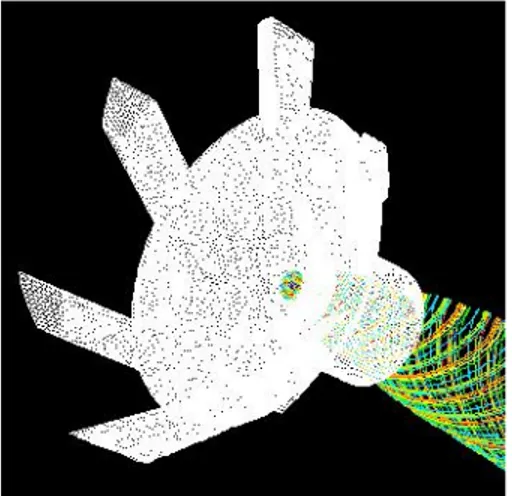
therefore they are included in this paper. Figure 15 is a 360o view of the flow-field inside the
nozzle and near the nozzle exit, and the flow-field is illustrated by three-dimensional, mean airflow path-lines from the air inlets. Air enters the nozzle tangential to the axis of symmetry and creates a strong swirling flow. Strong spiral air motions are obvious, which play a critical
role in the fuel atomization process. Figure 16 shows the mean airflow path-lines issued from the fuel inlet, where the surfaces with white colour represent the nozzle walls. Note that the flow moves in spiral paths, and gradually moves away from the nozzle centre towards the nozzle wall
due to the centrifugal force. It is expected that the centrifugal force for the liquid fuel would be much larger than air, and thus the fuel siphoned from the fuel inlet would eventually form a thin film against the nozzle wall before leaving the nozzle. This will be confirmed with general two-phase flow analyses in the future.
Fig. 15 Flow path-lines from air inlets, viewed from upstream
Fig. 16 Flow path-lines from fuel inlet, viewed from upstream
The axial and tangential velocity contours at the middle plane of the 60o sector in the
vicinity of the nozzle are presented in Fig. 17. The upper half shows the axial velocity plot overlapped with the airflow path-lines, while the lower half illustrates the tangential velocity contours. A strong toroidal vortex is clearly formed in the central region of the flow, which starts from where the fuel and air meet inside the nozzle and extends downstream of the nozzle. The maximum magnitude of the negative axial velocity is 42 m/s. Due to the centrifugal force, the velocity near the nozzle wall region is much high and reaches up to 99 m/s for the axial velocity and 127 m/s for the tangential velocity.
Fig. 17 Axial and tangential velocity contours around the nozzle
CONCLUSION
The numerical results together with the experimental measurements indicate that the installation of an inner tube in the pre-heating chamber modifies the flow-field, fuel spray trajectories, and reduces local velocities and turbulent strength. These contribute to the reduction in combustion noise. In particular, the modification of the fuel spray distribution in the
heating chamber plays a major role in the noise reduction of the burner at the low firing rate. As a result, the combustion in the pre-heating chamber is prevented and a stable combustion process is obtained.
The numerical results also show that the flow-field inside and around the nozzle is very complicated. A strong toroidal vortex is formed in the centre region of the nozzle, and outside the core region a high velocity swirling airflow is created to facilitate the fuel atomization process. The fuel issued from the nozzle centre is expected to form a thin liquid film against the nozzle wall prior to exiting the nozzle.
ACKNOWLEDGEMENT
The authors wish to acknowledge the assistance of Ms. Shelley Talwar (co-op student) in the nozzle spray PDPA measurements, and Ms. Rafiun Choudhury (co-op student) in post-processing of the numerical results.
REFERENCE
1. Mahan, J.R., "A Critical Review of Noise Production Models for Turbulent, Gas-Fuelled
Burners", NASA Contractor Report 3803, NASA, 1984.
2. Putnam, A.A., M.J. Murphy, and D.W. Locklin, "Burner Technology Bulletin: Control of Combustion Noise from Small Gas Burners. A reference Guide For Gas Burner Designers", Gas Research Institute, Report PB86-213956, GRI-85/0210, 1985.
3. Amara, F.B., Liu, S., Qian, W., Huang, C. and Liu, Z., “Modern Burner Unit Noise Emission Reduction”, Innovation Centre (Vancouver) NRC, Report, RC101.1, 2000. 4. Liu, Z.S., Huang, C., Qian, W.M., Liu, Z., Jiang, L.Y., Campbell, I., Yimer, I.,
“Self-Excited Combustion Oscillations of a Burner: Cause and Remedy,”Proceedings of the
10th International Congress on Sound and Vibration, Stockholm, Sweden, July 2003.
5. Liu, Z., Liu, Z.S., Amara, F.B., Qian, W., Huang, C. and Krishnappa, K., "Investigation of Noise Emission Reduction for a Field Kitchen Burner", will be published as a NRC research report.
6. Tannehill, J.C., Anderson, D.A., and Pletcher, R.H., “Computational Fluid Mechanics and Heat Transfer,” second edition, Taylor & Francis, 1997.
7. Shih, T.H., Liou, W.W. Shabbir, A., Yang, Z. and Zhu, J., “A New k-ε Eddy-Viscosity Model for High Reynolds Number Turbulent Flows – Model Development and Validation,” Computers Fluids, 24 (3), pp.227-238, 1995.
8. Kim, S.E., Choudhury, D. and Patel, B., “Computations of Complex Turbulent Flows Using the Commercial Code Fluent,” Proceedings of the ICASE/LaRC/AFOSR Symposium on Modeling Complex Turbulent Flows, Hampton, Virginia, 1997.
9. Kader, B., “Temperature and Concentration Profiles in Fully Turbulent Boundary Layers,” Int. J. Heat Mass Transfer, 24(9), pp. 1541-1544, 1993.