Publisher’s version / Version de l'éditeur:
Vous avez des questions? Nous pouvons vous aider. Pour communiquer directement avec un auteur, consultez la première page de la revue dans laquelle son article a été publié afin de trouver ses coordonnées. Si vous n’arrivez pas à les repérer, communiquez avec nous à PublicationsArchive-ArchivesPublications@nrc-cnrc.gc.ca. Questions? Contact the NRC Publications Archive team at
PublicationsArchive-ArchivesPublications@nrc-cnrc.gc.ca. If you wish to email the authors directly, please see the first page of the publication for their contact information.
https://publications-cnrc.canada.ca/fra/droits
L’accès à ce site Web et l’utilisation de son contenu sont assujettis aux conditions présentées dans le site LISEZ CES CONDITIONS ATTENTIVEMENT AVANT D’UTILISER CE SITE WEB.
Keynote paper at the Second Canada-Italy Workshop on 3DDigital Imaging and
Modeling, 2005
READ THESE TERMS AND CONDITIONS CAREFULLY BEFORE USING THIS WEBSITE. https://nrc-publications.canada.ca/eng/copyright
NRC Publications Archive Record / Notice des Archives des publications du CNRC :
https://nrc-publications.canada.ca/eng/view/object/?id=ad66985e-9469-4468-8444-25f170852cbb
https://publications-cnrc.canada.ca/fra/voir/objet/?id=ad66985e-9469-4468-8444-25f170852cbb
NRC Publications Archive
Archives des publications du CNRC
This publication could be one of several versions: author’s original, accepted manuscript or the publisher’s version. / La version de cette publication peut être l’une des suivantes : la version prépublication de l’auteur, la version acceptée du manuscrit ou la version de l’éditeur.
Access and use of this website and the material on it are subject to the Terms and Conditions set forth at
Experience and Challenges in 3D Digital Documentation of Frescoed
Walls and Ceilings from Images
National Research Council Canada Institute for Information Technology Conseil national de recherches Canada Institut de technologie de l'information
Experience and Challenges in 3D Digital
Documentation of Frescoed Walls and
Ceilings from Images *
El-Hakim, S.F., Gonzo, L., Girardi, S., Voltolini, F., Pontin, M.
May 2005
* published as Keynote paper at the Second Canada-Italy Workshop on 3D
Digital Imaging and Modeling. May 17-18, 2005. Padua, Italy. NRC 48226.
Copyright 2005 by
National Research Council of Canada
Permission is granted to quote short excerpts and to reproduce figures and tables from this report, provided that the source of such material is fully acknowledged.
EXPERIENCE AND CHALLENGES IN 3D DIGITAL DOCUMENTATION OF
FRESCOED WALLS AND CEILINGS FROM IMAGES
S. F. El-Hakim a, L. Gonzo b, S. Girardi b, F. Voltolini b, M. Pontin c a
VIT, NRC, Ottawa, Ontario, K1A 0R6, Canada – sabry.el-hakim@nrc-cnrc.gc.ca
bITC-irst, I-38050 Povo, Trento, Italy, – (lgonzo, girardi, fvoltolini)@itc.it
cCIRGEO, 35020 Legnaro, University of Padova – cirgeo@unipd.it
KEY WORDS: 3D model, Texture Mapping, Photo-Realism, Rendering, Visualization, Cultural Heritage.
ABSTRACT:
In this paper we report on our experience in creating photo-realistic virtual environments of frescoed surfaces to allow scientists, conservationists, historians, and tourists to closely study important frescoes at high level of details. In addition to allowing unlimited virtual access, this will also protect the frescoes from the damage that can be caused by opening the site to a large number of visitors. We address the main challenges associated with photo-realism or texture quality, and real-time interactive visualization and discuss available solutions. Where no effective solutions existed, we had to develop our own techniques. As case studies, we present results of modeling and visualization of two sites, both located at Buonconsiglio castle, one of the most important castles in Trentino in northern Italy. The first is the frescoed walls “Cycle of the Months”, a major masterpieces of international Gothic art that was painted around 1400. The second is the Gothic-Venetian Romanino loggia, named after the artist Girolamo Romanino (1484-1562) who decorated the ceiling and walls of the loggia, as well as the adjacent corridors, with remarkable frescoes in 1531.
1. INTRODUCTION
Although 3D geometric modeling techniques combined with high-resolution textures can potentially create realistic virtual environments, traditional texture mapping techniques usually produce uneven visual quality and may exhibit unacceptable geometric and radiometric distortions. The goal of this project is to create extremely realistic visual experiences. Two types of outcome are required: photo-realistic walkthrough movies, and 3D models that allow the user interactive visualization and manipulation, with the later being the most desirable but harder to create. The frescoes can be closely inspected just as if one is only a few centimeters from the real surface, which is not possible when actually visiting the site, especially for ceiling frescoes. The viewer will also have the freedom to look from any arbitrary angle, which is impossible with pre-recorded movies, videos, or photos. This allows more appreciation and understanding of the art. For our case studies, the “Cycle of the Months“ and “la Loggia del Romanino”, the texture quality can’t be compromised thus all types of distortion must be fully corrected. In addition, since user interactivity is important, a drop in frame rate is unacceptable therefore issues related to model size must be addressed. In the first phase of the project [El-Hakim et al, 2003], we selected the most appropriate 3D modeling technique and identified the main factors affecting the visual quality of the models and the performance of interactive visualization. A semi-automatic image-based 3D modeling approach was the most suitable for regular geometric primitives such as walls, groin- vaulted ceilings, and columns. Laser scanners, although capable of automatic generation of large number of points, were less suitable due to their high cost, particularly for the level of accuracy we need, and the required huge amount of data to capture all details without holes. Thus, a significant saving in cost and data acquisition and processing time was accomplished using only image-based techniques. When possible, we used existing software and hardware to accomplish our objectives. However, problems that have no
ready solution were tackled with new algorithms and specially developed software tools. In this paper we report on further advances in three areas:
1- Increasing the level of automation in image-based modeling of basic geometric surface shapes such as gothic ceilings. 2- Improving texture quality and photo-realism.
3- Real-time interactive visualization of large textured models. The remainder of the paper is organized as follows. We first provide an overview of image-based 3D modeling techniques suitable for this application. Then, we discuss the main issues related to the modeling and real-time rendering of highly textured real environments and the main techniques currently used to address these challenges. We then give details on our approach to achieve photo-realism and interactive visualization. Finally we present results of modeling and visualization of the “Cycle of the Months“ and “la Loggia del Romanino”.
2. IMAGE-BASED 3D MODELING
Here, we give a short review of current image-based modeling techniques suited for regular geometric primitives. Traditional image-based measurement and modeling techniques, such as standard photogrammetry, require extensive human interaction. Efforts to completely automate the process of taking images, camera pose estimation, self-calibration, point 3D coordinates, and creating the 3D model, while promising, are thus far not always successful. The full-automated procedure, which is widely reported in computer vision [e.g. Pollefeys et al, 1999, Liebowitz, et al, 1999], starts with a sequence of images taken by an un-calibrated camera. The system automatically extracts interest points, like corners, sequentially matches them across views, then computes camera parameters and 3D coordinates of the matched points using robust techniques. The key to the success of this fully automatic procedure is that successive
images must not vary significantly, thus the images have to be taken at short intervals. The first two images are usually used to initialize the sequence. This is done in a projective geometry basis and is usually followed by a bundle adjustment. Self-calibration to compute the intrinsic camera parameters, usually only the focal length, follows in order to upgrade the projective construction into a metric one, up to scale. The next step, the creation of the 3D model, is more difficult to automate and is usually done interactively to define the topology and edit or post process the model. An output model based only on the automatically extracted points will usually consist of surface boundaries that are irregular and overlapping and need some assumption, like planes and plane intersections, to be corrected. For large structures and scenes, since the technique may require a large number of images, the creation of the model entails a significant human interaction regardless of the fact that image registration and a large number of 3D points were automatically computed. The degree of the modeling automation increases when certain assumptions about the object such as those found in architectures can be made. Since automated image-based methods rely on features that can be extracted from the scene, occlusions and un-textured surfaces are problematic. We often end up with areas with too many features that are not all needed for modeling, and areas without any or have minimum features that will not produce a complete model.
The most impressive results remain to be those achieved with interactive approaches. Rather than full automation, a hybrid easy to use system, the well-known Façade, has been developed [Debevec et al, 1996] to create 3D models of architectures from small number of photographs. The basic geometric shape of a structure is first recovered using models of polyhedral elements. In this interactive step, the actual size of the elements and camera pose are captured assuming that the camera intrinsic parameters are known. The second step is an automated matching procedure, constrained by the now known basic model to add geometric details. The approach proved to be effective in creating relatively accurate and realistic models. The drawback is the high level of interaction. Also since assumed shapes determine camera poses and all 3D points, the results are as accurate as the assumption that the structure elements match those shapes. The Façade approach has inspired several research activities to automate it. Werner and Zisserman, 2002, proposed a fully automated Façade-like approach. Instead of the basic shapes, the principal planes of the scene are created automatically to assemble a coarse model. These are three dominating directions that are assumed to be perpendicular to each other. Like Façade, the coarse model guides a more refined polyhedral model of details such as windows, doors, and wedge blocks. Since this is a fully automated approach, it requires feature detection and closely spaced images for successful automatic matching and camera pose estimation. Schindler and Bauer, 2003, proposed a similar approach. Dick et al, 2001, proposed another automated Façade-like approach. It employs model-based recognition technique to extract high-level models in a single image then use their projection into other images for verification. The method requires parameterized building blocks with a priori distribution defined by the building style. The scene is modeled as a set of base planes corresponding to walls or roofs, each of which may contain offset 3D shapes that model common architecture elements such as windows and columns. Again, the full automation necessitates feature detection and projective geometry approach, however the technique used here also employs planner constraints and perpendicularity between planes to improve the matching process. Lee and Nevatia,
2003, developed a semi-automatic technique to also model architectures. The camera is calibrated using the known shapes of the buildings being modelled. The models are created in hierarchical manner by dividing the structure into basic shape, facade textures, and detailed geometry such as columns and windows. The detailed geometry modelling is an interactive procedure that requires the user to provide shape information such as width, height, radius, and spacing then, the shape is completed automatically.
3. ISSUES IN REALISM AND VISUALIZATION We divide the problems into those affecting visual quality or photo-realism (photo-realism means no difference between the rendered model and a photograph taken from the same viewpoint), and those affecting real-time or interactive visualization. Obviously the purpose of visualization is to provide smooth navigation through the model. This should be at a rate of at least 20 frames-per-second otherwise human brain can detect latency or jitter, even loss of interactivity may occur. For most cases with current hardware, it is usually impossible to achieve both photo-realism and smooth navigation without some compromise and using creative rendering techniques. 3.1 Photo Realism
Traditional texture mapping techniques, which are simply draping static imagery over geometry, are not sufficient to represent reality. Several geometric and radiometric distortions, as well as aliasing and other abnormalities can severely impede the visual quality. In the following sections, we will discuss the issues affecting photo-realism, mainly those affecting frescoed surfaces, and suggest possible solutions to reduce their effect. We will not discuss factors such as limited dynamic range of digital images since they have small effect on our application. 3.1.1. Distortions from geometric sources: For historically important frescos, it is crucial to preserve every line and minute painting detail. The textures on the models can be visibly affected by small geometric errors. Weinhaus and Devich, 1999, cover the geometric distortions of texture mapping, mainly those resulting from the various transformations. Here we divide sources of geometric texture errors into three categories:
3.1.1.1. Mapping between triangle plane and image plane: The correct mapping between the triangle plane and the image plane is given by a projective transform. Since most viewers do not use this transform, distortion arises especially for large triangles. For example the projection of a straight line inside the triangle may become crooked. In addition, after the correct mapping is computed and the texture is warped, the image must be re-sampled or filtered. The easiest texture filtering method is point sampling, wherein the texture value nearest the desired sample point is used. But in general, this results in strong aliasing artifacts. To get rid of those artifacts, sophisticated filtering methods are needed such as space variant filters whose shape varies as they move across the image.
3.1.1.2. Camera calibration and image registration: When cameras with standard lenses are used, lens distortion corrections must be applied else geometric distortions, like line discontinuity, will be visible at common edges of adjacent triangles mapped from different images. It is therefore important that full camera calibration is applied and that it
remains valid for all images by either keeping camera settings constant or applying self-calibration. Accurate image registration, mainly photogrammetric bundle adjustment, must also be implemented to minimize geometric distortions. 3.1.1.3. The assumptions made in surface reconstruction: Too large deviations of the triangle mesh from the underlying true object surface give rise to geometric errors. Since a triangle represents a plane, applying too large triangles on even slightly curved surfaces will results in features near the edges projected on the wrong surface or disappear altogether. This has been witnessed frequently with frescos and required adding more 3D points to the surfaces at appropriately selected locations. 3.1.2. Distortions due to radiometric characteristics: The effect of such distortion is usually visible along common edges of adjacent triangles mapped from different images. Due to variation in lighting, surface specularity, and variations in camera gain settings, colour and intensity for a surface element shown in different images will not agree. Variation in the sensed brightness between images will result when taking images from different locations and at varying ambient lighting. When these images are stitched together, discontinuity artifacts are usually visible.
The digitized brightness value for a pixel is not a measure of scene radiance (radiance is the amount of light energy reflected from a surface in all directions). There is an unknown non-linear mapping between the pixel value and the scene radiance. This non-linearity is largest near the saturated part of the response curve. Knowing the response function allows merging images taken at different exposure setting, different angles, or different imaging devices. The inverse of the response function is used to recover the scene radiance, up to a scale [Debevec and Malik, 1997]. The response function can be applied to any image taken by the imaging system, therefore, we can determine the function for a given camera in a controlled environment as a calibration process then apply it to the project images.
Blending methods to create seamless texture maps have been developed [Bernardini et al 2001, Pulli et al, 1998, Rocchini et al, 2002, Wang et al, 2001]. Those techniques use the weighted average of pixel values of triangles in the overlapping sections between two adjacent textures. For example, Pulli et al, 1998, used best 3 views to calculate new texture image. The colors of the compatible rays are averaged together via a weighting scheme that uses three different weights: directional weight, sampling quality weight, and feathering weight. The task of the directional weight is to favor rays originating from views whose viewing direction is close to that of the virtual camera. Not only should the weight increase as the current viewing direction moves closer, but the other views’ weights should decrease. The sampling quality weight directly reflects how well a ray samples the surface. Their algorithm assigns to each ray/pixel of each input image a weight that is defined as the cosine of the angle between the local surface normal and the direction from the surface point to the sensor. The feathering weight is used mostly to hide artifacts due to differences in lighting among the input images. Guidon, 1997, achieved seamless continuity by radiometric normalization. He combines scene-wide statistical normalization (matching scene gray-level means and variances) with local operations such as feathering or blending in overlapped regions. Some blending techniques require a model with a uniform triangle size and shape and use this to select the size of the overlapped region. However, if the size of that
region is too small the seams between regions will not be completely removed. If the region is too large, important details on the frescoes will be blurred. To alleviate these problems, Baumberg, 2002, developed an automatic multi-band approach, which does not require uniform triangle size, and is designed to preserve the high-frequency detail in the overlapping region. When the lighting in the virtual environment where the texture map is used differs from the lighting under which the texture map was captured the resulting rendering will appear unrealistic without light-dependent texture mapping [Gelb et al, 2001]. However, this method adds considerably to the rendering processing time since the system repeatedly computes light directions using triangles normal.
On planner walls even when proper lighting is implemented, the rendering may look too smooth and unrealistically flat. An improvement can be achieved by applying bump mapping. This is done by introducing small variations in surface normals thus adding roughness and more realistic look to the lighted surface [Rushmeier 1997] without the need to model each wrinkle as a separate element.
3.1.3. Additional visible texture aberrations: When textured models are viewed from a long distance, aliasing, moiré effect, jagged lines, and other visible abnormalities may result. This is because when the surface is far away, a pixel on that surface may be associated with several texels from the original texture map. MIP-maps (MIP stands for ‘multum in parvo’), a sequence of textures each of which is a progressively lower resolution of the original image (by a factor of 2), is commonly used to solve this problem [Williams, 1983]. The most appropriate texture is selected depending on the polygon size or distance. Bilinear or tri-linear filtering (to remove aliasing) and texture memory caching are also needed. Since real-time re-sampling and filtering can be computationally expensive, the required filtered representations of the original texture may be pre-computed and stored. This will increase the total size of texture by a maximum of one third. Although most recent hardware supports MIP-mapping operations, the actual managing and set up of caching scheme is up to the application.
Another common source of visual problems is the blurring resulting from stretching the texture over surfaces, depending on camera position relative to the surface. Surfaces at large distance from the camera or at oblique angle will be covered by small part of the image. This small part needs to be stretched to cover the 3D surface, thus blurring and obviously degrading the texture quality. View-dependent texture mapping, by taking sufficient images and selecting the most appropriate image depending on the location of the surface, can solve this problem [Debevec et al, 1998, Ismert et al, 2003].
3.2 Interactive Visualization
Due to the fact that this project focuses on high quality textures, the texture size could end up being quite large. The rendering algorithm should be capable of delivering images at interactive frame rates, even for very large textures. We now discuss the main factors affecting the performance of a rendering system. 3.2.1. Processing and memory limitations: Specifications affecting processing speed on a given hardware are: number of geometric transformations that can be performed per second; the number of triangles that can be rendered with texture per second; the available main and texture memory; the disk and
network access speed (bandwidth); and data transfer rate from main memory to graphic card memory. Some of these hardware specifications will affect only start up time. For example significant computations are initially needed in order for the rendering software to build an internal representation of the scene graph. Also high bandwidth is crucial to load the model and texture in memory at reasonable time at start up. Humphreys et al, 2001 and Strengert et al, 2004, use parallel processors or clusters to cope with large models. Lario et al, 2005, use on-board video memory to store geometry information to reduce data transfer from main memory to graphic card, which is the main bottleneck.
3.2.2. Size of the geometric model: Most existing techniques for real-time rendering [Baxter et al, 2002, Cohen-Or et al, 2003] focus on the geometry (reducing the number of triangles) rather than the texture. For example, hierarchical levels of detail (LOD), where objects far away from the viewpoint are rendered with pre-sampled lower resolution representations, is a standard technique that is supported by most scene graph libraries. Hoek and Damon, 2004, review automatic model simplification and run-time LOD management techniques. They discuss LOD framework, LOD management, LOD simplification models and metrics for simplification and error evaluation. Cohen, et al 2003, developed a low level lightweight API system for geometric LOD that is integrated in the OpenGL library. It is a close-to-hardware minimalist approach that allows developers to add LOD to their system. Zack et al, 2002, describes a complete project where LOD is practically applied.
3.2.3. Size of the texture: For a project like this, the total texture size will likely be several hundreds of mega bytes. If the on-board texture memory is less than the active texture (the texture that must be in texture memory), swapping will occur resulting in noticeable performance degradation. Fortunately it is rare that all the textures are needed for one frame. To take advantage of this, two techniques are suitable for our case: view frustum culling, which skips rendering and loading into memory parts of the model that are outside the view frustum; and MIP-mapping, which was originally developed to reduce aliasing as discussed in section 3.1.3. If all the texture fit into texture memory then there is usually no problem, else the viewing application must work out a texture caching routine that decide on which texture to keep or move into memory and which to move to RAM, or even to the system virtual memory [Cline and Egbert, 1998, Dumont et al, 2001]. To make texture caching more efficient it is recommended to divide the scene into smaller uniform groups, each with a small texture with width and height that are a power of two. This makes it possible to control the file size and the rendering speed more precisely. Wei, 2004 proposed a tile-based texture-mapping algorithm by which it only physically store a small set of texture tiles instead of a large texture. The algorithm generates an arbitrarily large and non-periodic virtual texture map from the small set of stored texture tiles. Thus, only a small constant storage is used regardless of the size of texture. Another approach is adaptive texture maps [Kraus and Ertl, 2002, and Hwa et al 2004], i.e. texture maps with locally adaptive resolution and an adaptive boundary of the texture map’s domain instead of a rectilinear domain. The locally adaptive resolution permits continuous simplification, and allows efficient representation of fine details rather than increasing the resolution of the whole texture map. Adaptive boundaries save considerable memory costs if the texture data contains large empty regions, such as walls without
frescos. Another effective performance enhancement technique for both geometry and texture is occlusion culling [e.g. Zhang, 1998], which skips objects that are occluded by other objects or surfaces.
4. THE MODELING AND RENDERING PROCEDURE Figure 1 summarizes the modeling and rendering procedure used for this project. Some of these operations have already been described above or are self-explanatory. Those requiring more details are given in the following sections.
Figure 1: Overview of the modeling and rendering procedure 4.1. Semi-Automated Image-Based Modeling
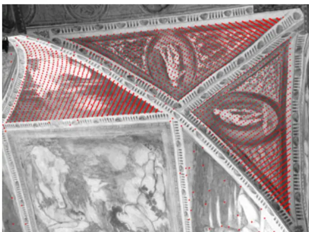
The image-based modeling approach used for this project is the semi-automatic technique initially described in El-Hakim, 2002, and partially implemented in the commercial ShapeCapture software [www.shapecapture.com]. The method, although similar in philosophy to some existing approaches like Façade, interactively measures only a small number of seed points in multiple images while most of the points are determined automatically. This achieves more flexibility and gives higher levels of detail than most other methods. In addition, the camera poses and 3D coordinates of seed points are determined without any assumption of the shapes but instead by bundle adjustment, with or without self-calibration depending on the given configuration. This achieves higher geometric accuracy regardless of the shape of the object. Here, we describe a specially developed procedure aimed at automatically adding large numbers of 3D points to surfaces of basic shapes that can be represented by an algebraic implicit function: F(X, Y, Z) = 0, such as groin vault ceiling. A number of seed points (at least 9 in case of quadric or cylindrical surface) are measured manually in multiple images on each section (figure 2).
A quadric is fitted to the seed points in each section. The section can have a rectangular or triangular boundary. Using the parameters of the quadric and the known camera internal and external parameters for a given image, any number of 3D points can be added automatically within the boundary of the section (figure 3). In order to achieve smooth surface model, we may need to generate hundreds of thousands of points per shape. Therefore, efficient modelling software, such as PolyWorks [http://www.innovmetric.com] is used for the triangular mesh.
Figure 3: Automatically generated 3D points (red dots). A column is automatically constructed after its direction, radius, and position have been automatically determined from four seed points, two on the corner of the top crown and two on the corners of its base. The ratio between the upper and the lower circle can be set in advance. It is set to less than 1.0 (about 0.85) to create a tapered column. From this information, points on the top and bottom circle of the column can be automatically generated in 3D resulting in a complete model. For windows and doors we need three (preferably four) corner points and one point on the main surface. By fitting a plane to the corner points, and a plane parallel to it at the surface point, the complete window or door is reconstructed. More details of the approach are given in El-Hakim, 2002.
4.2. Texture Mapping
Some corrections to texture maps, mentioned in the following sections, are done with our own in-house software. We also use HDR Shop from Paul Debevec [www.debevec.org] to determine the response function of the digital camera. Since the room shapes are rather simple, and the images were taken facing the surfaces and the frescos, there was no need for view-dependent texture mapping. Also since most room lighting dynamic range is not high, we did not require high dynamic range images. Near windows and other openings, where high dynamic range existed, we set the camera shutter speed to capture only the inside scene.
4.2.1. Selecting most appropriate image to texture: With sufficient image overlap, the texture of a triangle can be obtained from a number of different images. A reasonable choice is to select the image in which the triangle appears largest and taken along the normal. However, this may result in having too many different images assigned to adjacent triangles. One method to repair this is to locally re-assign triangle patches to images. In this step, the initial assignment is changed based on the image assignment of the adjacent triangles and the image area covered by the triangle in alternative images. In effect, local re-assignment generates
larger groups of triangles mapped from the same image and eliminates isolated triangle texture mappings. Thus, the number of triangle edges where adjacent triangles are mapped from different images is reduced.
4.2.2. Geometric corrections: The employed method defines a local texel coordinate system for each 3D triangle. The texel size, in object coordinates, can be set to the desired resolution. Projective transformation between the plane of the triangle and image plane is determined and used to re-sample the texture within each triangle. This is followed by low pass filter to remove high frequency noise introduced by this re-sampling. As mentioned in section 3.1.1 radial and tangential lens distortion [Faig, 1975] is used for all texture mapping transformations. 4.2.3. Radiometric corrections: Our approach for radiometric texture corrections has been originally developed in El-Hakim et al, 1998 and improved subsequently since. We address this problem by a correction method termed "global color adaptation" and another correction on a per-triangle basis, termed "local color adaptation". Here, the color means the color channel value (red, green, or blue). The global color adaptation estimates color offsets between images. The color differences along the border of adjacent regions of triangle sets are minimized by least-squares adjustment. The adjustment is much like in the case of a geodetic height network. Here the observed height differences are replaced with color differences along region borders. Additional weighted observations ensure non-singularity and prevent the offset from drifting away across larger scenes. The approach has been implemented in software tool that automatically correct adjacent images once the user points to a common region. An example of this color correction on a pair of original images (figure 4) can be seen in figure 5.
Figure 4: Two adjacent images before global correction.
5.1 The “Cycle of the Months” Frescos The local color adaptation modifies the colors of each triangle
to ensure smooth transitions to all adjacent triangles. However, this is not straightforward since if we observe an offset along one triangle edge and another along a second edge, it is unclear how to correct the colors in the vicinity of the triangle vertex where the two edges intersect. Thus, we have adopted a technique based on an iterative procedure. To force a gradual change to the colors within a triangle, we fit a plane to the color offsets observed at the triangle borders using a least-squares adjustment that minimizes these differences. After correcting the colors according to the plane parameters, this process is iterated several times. Usually, there are no noticeable changes after a few iterations.
In order to portray the room in the proper context, we needed to capture, in addition to the room itself, the outside view of the Aquila tower and the entrance to the room. Therefore, we created the following 3D models: the outside walls of the tower including part of the long walkway leading to the room, the entrance to the room from the walkway, the walls of the room, and the ceiling of the room. We used a 5 Mega-pixels (1920x2560 pixels) SLR digital camera. The size of the room [7.75 m x 5.95 m x 5.35 m (H)] required taking 16 images to cover the walls and 8 to cover the ceiling. This could take at least half an hour during which lighting conditions may change and result in inconsistent illumination. For the outer tower model and the entrance to the room through the walkway, 5 and 2 images were taken, respectively. This resulted in a total image size of 472 Mega-bytes. For texture mapping, the images were cropped to the size of the triangles to reduce texture size. The average texture resolution was 2 mm x2 mm area of the wall per pixel. Figure 6 shows a top view of the room with camera locations for wall images (white solid circles) and ceiling images (gray solid squares).
Another method to reduce texture discontinuities is to use texture blending, as described in section 3.1.2, instead of the adaptations. In this case, instead of correcting the colors of adjacent triangles, we compute the texture (color) from all the images where the triangle appears using a weighted average. While blending is an algorithmically simple approach that reduces geometric and radiometric discontinuities, it will usually introduce a visible blurring effect along the regions boundaries. Although techniques exist to reduce this effect [Baumberg, 2002], any remaining blurring may still be unacceptable for rich textures like the frescoes. It has to be decided from case to case which is the better choice: global and local color adaptation, which produces sharper texture maps but does not completely correct the texture differences at adjacent triangles; or texture blending which better reduces artifacts at adjacent triangles but tends to blur the textures.
4.3. Rendering
In order to achieve the desired performance on large model size, special software for interactive visualization, named “Il Teatro Virtuale” has been developed at VIT [Paquet and Peters, 2002] using scene graph tools. Those tools are data structures used to hierarchically organize and manage the contents of spatially oriented scene data. They offer a high-level alternative to low-level graphics rendering APIs such as OpenGL. Examples of scene graph supported languages are VRML, Java 3D, MPEG-4, and of course SGI Open Inventor which is the earliest of those. This PC-based loader is developed with Java 3D [http://www.javasoft.com] which, unlike other languages, gives complete control over the rendering process. We also use another technique, called GoLD (Geomophing of levels of details, Borgeat et al, 2005), also developed at VIT, for view-dependent real-time visualization of large multi-resolution geometric models. The method uses geomorphing to smoothly interpolate between geometric patches composing a hierarchical level of detail structure and to maintain seamless continuity between neighboring patches of the model.
Figure 6: Room top view with camera locations.
Figure 7: Wire-frame models of the different parts (clockwise: walls, ceiling, tower, and entrance)
5. RESULTS OF MODELING FRESCOED ROOMS
Results of the geometric modeling are shown in figure 7 in wire-frame. Mesh size was small (10,000 triangle), but texture size was about 160 Mega-bytes. After texture mapping, sometimes we needed to add extra points and reconstruct the model to account for small deviations from plane for some walls. For example in the corner shown in figure 8, we had to increase the number of points near the intersection between the two walls. When only using a small number of points and assuming planes in areas without points, the lines along the corner did not project on the correct wall and lines that span the two walls had visible discontinuity. This shows that any small To study the factors affecting photo-realism and interactive
visualization, we selected two sites located at Buonconsiglio castle, one of the most important castles in the Trentino region in northern Italy. The first is the frescoed room “Cycle of the Months”, one of the major masterpieces of international Gothic art that was painted by unknown artist around 1400. The second is the Gothic-Venetian Romanino loggia, named after the artist Girolamo Romanino (1484-1562) who decorated the ceiling and walls of the loggia as well as the adjacent corridors with outstanding frescoes in 1531.
geometrical error will be visible in this class of models with frescoed walls. In most other types of architecture, where walls have uniform colors, such errors may be tolerated and one can assume that the walls are planes.
Figure 8: A corner where geometric accuracy is critical.
Figure 10: La Loggia del Romanino
The size of the room [21.75 m x 7.80 m x 6.75 m (H)] required a total of 61 images (34 images for the walls and 27 images for the ceiling) at 8-mpixel each with 7.94 mm focal length using the Olympus 8080 digital camera. Average texture resolution was 1.25 mm x 1.25 mm of the ceiling per pixel. Full resolution images resulted in about 500 Mega-bytes of textures. Due to the complexity of the room, several independent models were created, for example the main room walls, the ceiling, and one for each window and pathway. The models were registered using common points. There were a total of about 1.6 million triangles in the 3D model. Figure 11 shows part of the wire-frame model of the room walls and columns (without the ceiling), while figure 12 depicts two different windows. Parts of the ceiling 3D model are shown in figures 13, 14, and 15. Using the approach described in section 4.1, large number of points was generated automatically on the ceiling, columns, and arches. The texture mapping approach described in 4.2 was applied. The ceiling was divided into groups each covered one of the panels. For each panel the image taken along the normal and in it the fresco covers the largest image area was selected for the texture.
Figure 9: Lighting variations, first and last image Without applying texture corrections, we noticed in the corner where one wall texture was taken from the first image and the other wall texture was taken from the last image (the 16th) that there are visible illumination differences (figure 9). This is because the difference in time between the two images was about 30 minutes, which was enough for the lighting conditions to change even though we used a flash. Correction to this problem was done with the technique presented in section 4.2.3. The three interior models (the walls, the ceiling, and the entrance) were registered in the same coordinate system using common points. The outside model of the tower was registered with the room wall model using the windows. The models were put together in 3dsmax. This software was also used along with Adobe Premier to create the walkthrough movie. An interactive full model in VRML was also created. All the geometric and radiometric corrections, as discussed in section 4.2, were applied to the textures.
5.2 La Loggia del Romanino
Figure 10 shows four views from the four corners of the loggia del Romanino. The loggia connects different parts of the Buonconsiglio castle buildings and floors and opens onto an internal garden: the lion’s courtyard. It is entirely frescoed with metaphorical scenes, many of which have biblical references, but there are also contemporary-world depictions, such as musical concerts that were typical entertainment of Renaissance courts. Renaissance style frames divide the different panels.
Figure 12: Two different detailed widow models.
Figure 13: Point clouds of part of the ceiling.
Figure 14: Wire-frame and shaded model of one panel.
Figure 15: Wire-frame and textured ceiling panel. Currently, only the 3D model has been created. A walkthrough movie is now being produced.
6. CONCLUDING REMARKS
The semi-automatic image based modeling and texture-mapping techniques presented in this paper proved to be very effective for basic geometric surface primitives. We have created
walkthrough movies and interactive 3D models that can provide a realistic experience to the user. The current models work in real-time on a 3-GH PC with 128 MB texture memory and 1GB RAM using our rendering software. Comparison with laser scanning techniques will be the subject of future work.
ACKNOWLEDGEMENTS
This project is funded by the “Provinicia Autonoma di Trento”. The Castello del Buonconsiglio gave us unrestricted access to the rooms during non-visiting hours. Dr. Claus Brenner, University of Hanover, Germany, and Lilia Legrain, ICAM, France, contributed to the radiometric correction software.
REFERENCES
Baumberg, A., 2002. Blending images for texturing 3D models, BMVC’2002, pp. 404-413.
Baxter III, W.V., Sud, A., Govindaraju, N.K., Manocha, D., 2002. GigaWalk: Interactive walkthrough of complex environments. University of North Carolina at Chapel Hill Technical Report TR02-013.
Bernardini, F., Martin, I. M., Rushmeier, H., 2001. High-quality texture reconstruction from multiple scans. IEEE Trans.
Visualization and Computer Graphics, 7(4), Oct., pp. 318-332.
Borgeat, L., Godin, G., Blais, F., Massicotte, P., Lahanier, C., 2005. GoLD: Interactive display of huge colored and textured models, SIGGRAPH’2005 (to appear).
Cline, D., Egbert, P.K., 1998. Interactive display of very large textures. Proc. IEEE Visualization’98, pp. 343-350.
Cohen-Or, D., Chrysanthou, Y., Silva, C.T., Durand, F., 2003. A survey of visibility for walkthrough applications. IEEE
Trans. Visualization and Computer Graphics, to appear.
Cohen, J., Luebke, D., Duca, N., Schubert, B., 2003, GLOD: Level of Detail for the Masses, John Hopkins U. Tech. Report: URL: http://www.cs.jhu.edu/~graphics/TR/TR03-4.pdf. Debevec, P.E., C.J. Taylor, J. Malik, 1996. Modelling and rendering architecture from photographs: A hybrid geometry and image-based approach. SIGGRAPH’96, pp. 11–20.
Debevec, P.E., Malik, J., 1997. Recovering high dynamic range radiance maps from Photographs. Proc. SIGGRAPH’97, pp. 369-378.
Debevec, P.E., Yu, Y., Borshukov, G.,1998. Efficient View-Dependent Image-Based Rendering with Projective Texture-Mapping. In 9th Eurographics Rendering Workshop, Vienna, Austria, June, pp. 105-116.
Dick, A.R., P.H.Torr, S.J. Ruffle, R.Cipolla, 2001. Combining single view recognition and multiple view stereo for architectural scenes, Proc. 8th IEEE International Conference on Computer Vision (ICCV'01), pp. 268-274.
Dumont, R., Pellacini, F., Ferwerda, J.A., 2001. A perceptually-based texture caching algorithm for hardware-perceptually-based rendering. Proc. 12th Eurographics Workshop on Rendering, pp. 246-256.
El-Hakim, S.F., Brenner, C., Roth, G., 1998. A multi-sensor approach to creating accurate virtual environments, ISPRS J.
for Photogrammetry & Remote Sensing, 53(6), pp. 379-391.
El-Hakim, S.F., 2002. Semi-automatic 3D reconstruction of occluded and unmarked surfaces from widely separated views. Proc. ISPSRS Comm. V Sym., Corfu, Greece, pp. 143-148. El-Hakim, S.F., Gonzo, L., Picard, M., Girardi, S., Simoni, A., Paquet, E., Viktor, H., Brenner, C., 2003. Visualization of highly textured surfaces. 4th Int. Symp. VAST2003, Brighton, UK, 5-7 November 2003, pp. 231-240.
Faig, W., 1975, Calibration of close-range photogrammetric systems. Photogrammetric Engineering & Remote Sensing, 41(12), pp. 1479-1486.
Gelb, D., Malzbender, T., Wu, K., 2001, Light-dependent texture mapping. HP Labs Tech Report: HPL-98-131(R.1). Guindon, B., 1997. Assessing the radiometric fidelity of high resolution satellite image mosaics. ISPRS J. Photogrammetry &
Remote Sensing. 52(5), October, pp. 229-243.
Heok, T.K., Damen, D., 2004. A review of level of detail, IEEE Int. Conf. Computer Graphics, Imaging and Visualization (CGIV’04).
Humphreys, M., et al, 2001. WireGL: a scalable graphics system for clusters, SIGGRAPH’01, pp. 129-140. []
Hwa, L.M., Duchaineau, M.A., Joy, K.I., 2004, Adaptive 4-8 texture hierarchies, IEEE Visualization, Austin, Texas, Oct. Ismert, R.M., Bala, K., Greenberg, D.P., 2003. Detail synthesis for image-based texturing. Interactive 3D Graphics (I3D) Conf., Monterey, CA.
Kraus, M., Ertl, T., 2002. Adaptive texture maps, Eurographics Conf. On Graphics Hardware, pp.7-15.
Lario, R., Pajarola, R., Tirado, F., 2005. Cached geometry manager for view-dependent LOD rendering, WSCG’2005, Jan. 31- Feb. 4, Plzen, Czech Republic.
Lee, S.C., Nevatia, R., 2003. Interactive 3D Building Modeling Using a Hierarchical Representation, IEEE Workshop on Higher-Level Knowledge in 3D Modeling and Motion (HLK) part of ICCV 2003, Nice, pp. 58-65.
Liebowitz, D., A. Criminisi, A. Zisserman, A., 1999. Creating Architectural Models from Images, EUROGRAPHICS ’99, 18(3).
Paquet, E., Peters, S., 2002. Collaborative Virtual Environments Infrastructure for E-Business, Int. Conf. Infrastructure for e-Business, e-Education, e-Science and e-Medicine on the Internet - SSGRRw02, L'Aquila, Italy.
Pollefeys, M., R. Koch, L. Van Gool, 1999. Self-calibration and metric reconstruction in spite of varying and unknown intrinsic camera parameters. Int. J. of Computer Vision, 32(1), pp. 7-25.
Pulli, K., Abi-Rached, H., Duchamp, T., Shapiro, L.G., Stuetzle, W., 1998. Acquisition and visualization of colored 3-D objects. Proc. Int. Conf. Pattern Recognition, pp. 99-108. Rocchini. C., Cignoni, P., Montani, C., Scopigno, R., 2002. Acquiring, stitching and blending diffuse appearance attributes on 3D models. The Visual Computer, 18, pp. 186-204.
Rushmeier, H., Taubin, G., Gueziec, A., 1997. Applying shape from lighting variation to bump map capture. Proc. Eurographics Rendering Workshop, pp. 35-44.
Schindler, K., Bauer, J. 2003. A model-based method for building reconstruction. Proc. ICCV workshop on Higher-Level Knowledge in 3D Modeling and Motion (HLK'03), Nice, France, 2003
Strengert, M., Magallon, M., Weiskopf, D., Gothe, S., Ertl, T., 2004. Hierarchical visualization and compression of large volume datasets using GPU clusters, Eurographics Symposium on Parallel Graphics and Visualization (2004), pp. 1–7. Wang, L., Kang, S.B., Szeliski, R., Shum, H.-Y., 2001. Optimal texture map reconstruction from multiple views, Proc. Computer Vision and Pattern Recognition (CVPR01).
Wei, Li-Yi, 2004. Tile-based texture mapping on graphics hardware, Eurographics Conf. On Graphics Hardware.
Weinhaus, F.M., Devich, R.N., 1999. Photogrammetric texture mapping onto planar polygons, Graphical Models and Image Processing, 61(1), pp. 61-83.
Werner, T., Zisserman, A., 2002. New technique for automated architectural reconstruction from photographs. Proc. 7th European Conf. Computer Vision, Copenhagen, May.
Williams, L., 1983. Pyramidal Parametrics. Computer
Graphics (Proc. SIGGRAPH ’83), volume 17, July, pp. 1–11.
Zack, C., et al, 2002. Modeling and visualizing the cultural heritage data set of Graz,International Symposium on Virtual Reality, Archaeology, and Cultural Heritage (VAST 2001), Glyfada, Greece, pp. 219-226.
Zhang, H., 1998. Effective occlusion culling for the interactive display of arbitrary models, Ph. D. Thesis, Department of Computer Science, UNC-Chapel Hill.