HAL Id: hal-00005889
https://hal.archives-ouvertes.fr/hal-00005889
Submitted on 9 Jul 2005
HAL is a multi-disciplinary open access
archive for the deposit and dissemination of
sci-entific research documents, whether they are
pub-lished or not. The documents may come from
teaching and research institutions in France or
abroad, or from public or private research centers.
L’archive ouverte pluridisciplinaire HAL, est
destinée au dépôt et à la diffusion de documents
scientifiques de niveau recherche, publiés ou non,
émanant des établissements d’enseignement et de
recherche français ou étrangers, des laboratoires
publics ou privés.
VITRUV - Imaging close environments of stars and
galaxies with the VLTI at milli-arcsec resolution
Fabien Malbet, Jean-Philippe Berger, Paulo Garcia, Pierre Kern, Karine
Perraut, Myriam Benisty, Laurent Jocou, Emilie Herwats, Jean-Baptiste
Lebouquin, Pierre Labeye, et al.
To cite this version:
Fabien Malbet, JeanPhilippe Berger, Paulo Garcia, Pierre Kern, Karine Perraut, et al.. VITRUV
-Imaging close environments of stars and galaxies with the VLTI at milli-arcsec resolution. The Power
of Optical/IR Interferometry: Recent Scientific Results and 2nd Generation VLTI Instrumentation,
The European Southern Observatory (ESO), 2005, Garching bei München, Germany. in press.
�hal-00005889�
ccsd-00005889, version 1 - 9 Jul 2005
and galaxies with the VLTI at milli-arcsec
resolution
Fabien Malbet1 , Jean-Philippe Berger1 , Paulo Garcia2 , Pierre Kern1 , Karine Perraut1 , Myriam Benisty1 , Laurent Jocou1 , Emilie Herwats1,3, Jean-Baptiste Lebouquin1 , Pierre Labeye4 , Etienne Le Coarer1 , Olivier Preis1 , Eric Tatulli1, and Eric Thi´ebaut5
1
Laboratoire d’Astrophysique de Grenoble, BP 53, F-38041 Grenoble cedex 9, France [email protected]
2
Centro de Astrof´ısica da Universidade do Porto, Rua das Estrelas, 4150-762 Porto, Portugal
3
Universit´e de Li`ege, Li`ege, Belgique
4
CEA-LETI, Grenoble, France
5
Centre de Recherche en Astrophysique de Lyon, Lyon, France
Summary. The VITRUV project has the objective to deliver milli-arcsecond spectro-images of the environment of compact sources like young stars, active galax-ies and evolved stars to the community. This instrument of the VLTI second genera-tion based on the integrated optics technology is able to combine from 4 to 8 beams from the VLT telescopes. Working primarily in the near infrared, it will provide intermediate to high spectral resolutions and eventually polarization analysis. This paper summarizes the result from the concept study led within the Joint Research Activity advanced instruments of the OPTICON program.
1 Introduction
The VLT interferometric facility is unique in the world, since it offers giant 8m telescopes, 2m auxiliary telescopes and the necessary infrastructure to combine them. With four 8m unit telescopes (UTs) equipped with adaptive optics systems, four 1.8m auxiliary relocable telescopes (ATs) equipped with tip-tilt correction, a maximum separation of 130m for UTs and 200m for ATs, 6 available delay lines, slots foreseen for 2 more ones, a dual feed capability (PRIMA) and a complete system control, the VLTI is the best site to propose the first optical interferometer to deliver routinely aperture synthesis images like the millimeter wave interferometers are already doing for more than 10 years. The quality of the images will be as good as the ones delivered by the IRAM Plateau de Bure Interferometer with six 15m antennas and a maximum
2 F. Malbet et al.
baseline of 500m at 1-3mm. The VLTI will be for a long time the only facility with 10m class telescopes able to provide images with 1mas angular resolution in optical wavelength.
We propose a second generation instrument for the VLTI, called VITRUV, aimed at taking the best profit of the imaging capability of the array, espe-cially within the PRIMA framework. The science objectives of VITRUV are focused on the kinematics and morphology of compact astrophysical objects at optical wavelengths like the environment of AGN, star forming regions, stellar surfaces and circumstellar environments. The instrument will deliver aperture synthesis images with spectral resolution as the final data product to the astronomer.
The specifications can be summarized as: • beam combiners for 4T and 8T operation, • a temporal resolution of the order of 1 day, • 2 or 3 spectral resolutions from 100 to 30000, • image dynamics from 100 to 1000,
• a field of view up to1 arcsec
• initial wavelength coverage from 1 to 2.5 microns that could be extended from 0.5 to 5 microns.
The technology that is contemplated at this stage is integrated optics because it offers simplicity, stability especially for phases, operational liability, and high performances. This technology has been already successfully validated on the 3 telescope IOTA interferometer where the system routinely delivers visibilities and closure phases for 3 baselines [1, 2] and on the VLTI to replace the fiber coupler of VINCI [3].
2 Science objectives
The science cases definition methodology was to concentrate in a few fields where VITRUV can make a substantial contribution, without being fully ex-haustive. We list here the four science cases for the VITRUV concept where significant advance can be achieved:
1. Studying the formation of stars and planets by direct spectro-imaging of their inner disk regions, from the orbits of Mercury to Neptune.
2. Imaging the magnetic and convective hallmarks of stellar surfaces. 3. Connecting the geometries of the close environments of evolved stars with
their progenitors.
4. Probing the close environment of active gaglactic nuclei and supermassive black holes.
Further details are given in the VITRUV Science Cases in this volume [4]. The top level technical requirements has been deduced from these science requirements:
Fig. 1. Vitruv concept
• One night imaging capability thanks to the largest simultaneous (u,v) plane coverage while combining simultaneously between 4 and 8 beams (can be downgraded to 6)
• Spectral resolution from 100 up to 30,000
• Sensitivity and spectral resolution requires phase stabilization (fringe tracker) and eventually dual beam referencing (PRIMA).
VITRUV has been designed to be the instrument for phase reference imag-ing (PRIMA) with the telescopes available on the site. In addition it can perform phase closure imaging in the case where there is no adequate ref-erence star in the field. Therefore it is important to consider VITRUV in the PRIMA development scheme although this service is not mandatory for relatively bright targets (up to K = 11 − 13 with the UTs).
3 VITRUV concept
VITRUV is a non-direct imaging instrument. It measures electromagnetic field complex coherence at different spectral resolutions, different polarization
4 F. Malbet et al.
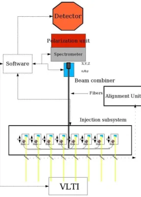
Fig. 2. General view of the VITRUV instrument
states for a maximum of 28 baselines (8 telescopes). Visibilities, phases and closure phases are the raw observables. It is a single-mode instrument with field of view capability of a few Airy disks. The data product is the recon-structed spectral image cube at all wavelengths.
VITRUV is designed to simplify operation as much as possible. A self-aligned integrated optics (IO) beam combiner is at the heart of the instrument concept. At this stage of the study we plan to have four beam combiners to cover the J, H, K bands:
• optimized 4-way beam combiner for J/H band • 5 to 8 way beam combiner for J/H band • optimized 4-way beam combiner for K band • 5 to 8 way beam combiner for K band,
and two additional ones to extend to R/I and L bands. Each 8-way beam combiner has a maximum of 8 inputs and can be used with whatever combi-nation of telescopes is available (i.e. from 4 to 8). In order to limit the size of the instrument, specific injection modules under development at LAOG will allow selecting which combiner is in use at a given time. VITRUV concept has a spectral resolution capability with an optional polarization state ca-pability which will be traded-off between astrophysical goals and instrument complexity.
The VITRUV instrument (see Fig. 2) can be described by 6 subsystems as follows.
3.1 Injection subsystem
This system has two functions: (1) to inject VLTI beams into VITRUV beam combiner fibers, and (2) to select the chosen combiner thanks to a motorized translation. Focus will be made thanks to off-axis parabolae in order to dis-card chromaticity effects. At the focus of each parabola a miniaturized fiber positioner [5] holds N fibers, N being the number of beam combiners (4 in the JH/K only version). Fiber numerical apertures will be chosen in order to optimize an average coupling covering the VITRUV band pass. A 1D transla-tion allows us to select between the N fibers. A miniaturized fiber positransla-tioner allows on-sky flux optimization. Each injection module is located on a trans-lation stage designed to equalize optical paths for internal fringe acquisition purposes.
3.2 Integrated optics beam combiners
The optical beam combining function will be achieved thanks to integrated optics (IO) technologies that allow embedding single mode optical circuits in glass or silica chips. As of today we plan to use two different types of beam combiners, one for 4-way beam combination and one for 5 to 8-way beam combination. The beam combination principle (coaxial or multiaxial) is different between the two in order to maximize the signal-to-noise ratio [6].
For the JH/K only version of VITRUV the 4 beam combiners are stacked together (or integrated in the same chip, not defined as of today) on a remotely controlled motorized 6-axes positioner which allows us to position the beam combiner output in front of the detector. Only one beam combiner is opera-tional at the same time, selected by the injection module (i.e. on wavelength band) and, if required, by the combiner positioner.
The total number of degrees of freedom for VITRUV is 8 + 56 = 64 dof.
3.3 Spectrometer
Preliminary design of the spectrometer will be mainly constrained by science case requirements and technical issues. It will include motorized axes in order to select spectral resolution mode. IO combiners add a supplement interesting property in the sense that the chip can act as an entrance slit for a spectrom-eter and does not require optical anamorphous transform.
3.4 Detector
The detector choice is still at its premises. The JHK detector will be a nitro-gen cooled array with low readout noise but fast enough to be able to read quadrants and sample spectrally dispersed fringes within the atmosphere per-turbations eventually compensated by the fringe tracker.
6 F. Malbet et al.
Performant detectors can also now be found for the R/I part of the spec-trum and L band. The proposed visible extension requires an additional de-velopment for a low noise fast read out detector or photon-counting detector, with performances close to the performances of an AO visible wavefront sensor (see OPTICON development in JRA2 based on an EEV detector 288x288).
3.5 Software
Software development is required to ensure control of all VITRUV motorized elements, camera readout and data acquisition, interface with VLTI software, data reduction, image reconstruction. We do not expect that the VITRUV instrument control software to be very different from the AMBER software except for the number of input beams. We plan to use the maximum of the heritage from the AMBER software.
Like for AMBER the data reduction software (DRS) will be part of the package, but in addition we are working in collaboration with the Jean-Marie Mariotti Center (JMMC, see http://mariotti.fr) to provide image recon-struction software to provide reconstructed images to the users.
3.6 Polarization control
As of today two VITRUV instrumental modes that will deal with polarization issues are contemplated: polarization split at the output recording two linear polarizations and relax constrains due to the use of birefringent waveguides. With proper calibration this mode should allow to provide information on the degree of linear polarization of the source; a full polarization analyzing module (should the science case demonstrate its importance) where linear and circular differential polarization states will be measured.
4 VITRUV within the VLTI infrastructure
VITRUV is an instrument that requires a full and operational VLTI infras-tructure.
UT operation requires adaptive optics capability which is already available with the MACAO systems. The availability of AO systems on AT would sig-nificantly improve the capabilities of the instrument, mainly to reach shorter wavelengths ideally down to the R band.
The considered concept allows long exposure acquisition requested for the high spectral resolution mode. Therefore the sensitivity and the spectral cov-erage of the instrument will be highly improved with fringe tracking capabil-ities6
. In addition with the PRIMA facility if adapted to all telescope sub-systems, the imaging capability can be pushed towards fainter sources with a bright reference nearby.
6
This study can be developed in parallel if this fringe tracking facility exists, but if not then it should be added to the project.
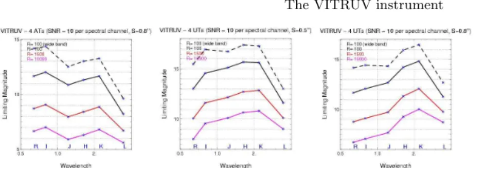
Fig. 3. Limiting magnitude through the VITRUV wavelength coverage. Left panel with 4 ATs, middle panel with 4 UTs and an average seeing of 0.8”, and right panel with 4 UTs and an exceptional seeing of 0.5”.
5 Expected performances
The performances of the VITRUV instrument depend on the sensitivity of the fringe tracker. We assume here that this fringe tracker can work up to K=11. Since the fringe tracker is a low pass filter, we assume that the piston correction is almost perfect over a few seconds.
We have computed SNR curves with a perfect external PRIMA fringe tracker. The limiting magnitude of this PRIMA fringe tracker should be the one computed by AMBER in the low resolution mode, i.e. K = 11 − 13 depending on average seeing conditions. We assumed in our calculation that the AO guide star is bright and is V = 5. The conditions remain about the same up to V = 13. Since the fringes are stabilized, we used a 100s elementary exposure time. We have not yet fully investigated the dual feed option in simulations (losses due anisoplanetism).
For imaging the requested visibility accuracy does not need to be very stringent. In mm radio interferometry, maps are produced with 10% visibility errors. More important is the (u, v) coverage. A typical visibility accuracy below 1% and phase accuracy of the order of 1 degree is sufficient and already achieved [7, 3, 1, 2].
The field of view of VITRUV is fundamentally limited by the FOV ac-cessible by the injection fibers, i.e. in K 250 mas with the ATs and 60 mas with the UTs. Most of the science which is contemplated focuses on compact objects within this limit. However like for radio interferometry, we know that we can extend the FOV by performing mosaicing (Tatulli, 2004).
We focus the project on objects with a bright central reference, but no so bright that we need to cancel it. Basically a dynamic range between the faintest and the brightest features in the image between 100 and 1000 are achievable. We have started to build a software-based end-to-end simulator of VITRUV which allows us to investigate this issue with more accuracy.
8 F. Malbet et al.
6 Project management
At this stage, it is difficult to predict an accurate evaluation of the resources required for the project.
Cost. A first rough estimation for an instrument operable in the 1-2.5µm range leads to a cost of 1.2 MEuros. The additional cost to extend the wave-length range (0.6 - 4 µm) is 1.1 MEuros. This extension includes an additional camera for the visible and some technological development for the integrated optics components.
Manpower. The 1-2.5 µm instrument requires a manpower support of 56 FTE for its design and construction. The required additional manpower is 22 FTE for a 0.6-4 µm extension.
Schedule. The required time to achieve the full manufacturing of the 1-2.5 µm instrument is 3.5 years. Six additional months will be required to achieve the extended version, taking into account that main additional devel-opments for the proposed extension will be carried out in parallel during the whole project.
Collaborations. For the moment, a formal consortium has not yet been established. We are waiting for the end of the selection process to start working on this issue. We are very open to various forms of collaborations.
References
1. Monnier, J.D., Traub, W.A., Schloerb, F.P., Millan-Gabet, R., Berger, J.P., Pe-dretti, E., Carleton, N.P., Kraus, S., Lacasse, M.G., Brewer, M., Ragland, S., Ahearn, A., Coldwell, C., Haguenauer, P., Kern, P., Labeye, P., Lagny, L., Mal-bet, F., Malin, D., Maymounkov, P., Morel, S., Papaliolios, C., Perraut, K., Pearl-man, M., Porro, I.L., Schanen, I., Souccar, K., Torres, G., Wallace, G.: First Results with the IOTA3 Imaging Interferometer: The Spectroscopic Binaries λ Virginis and WR 140. ApJ602 (2004) L57–L60
2. Kraus, S., Schloerb, F.P., Traub, W.A., Carleton, N.P., Lacasse, M., Pearlman, M., Monnier, J.D., Millan-Gabet, R., Berger, J.P., Haguenauer, P., Perraut, K., Kern, P., Malbet, F., Labeye, P.: Infrared Imaging of Capella with the IOTA Closure Phase Interferometer. AJ130 (2005) 246–255
3. LeBouquin, J.B., Rousselet-Perraut, K., Kern, P., Malbet, F., Haguenauer, P., Kervella, P., Schanen, I., Berger, J.P., Delboulb´e, A., Arezki, B., Sch¨oller, M.: First observations with an H-band integrated optics beam combiner at the VLTI. A&A424 (2004) 719–726
4. Garcia, P., Berger, J.P., Corradi, R., Forveille, T., Harries, T., Henri, G., Malbet, F., Marconi, A., Perraut, K., Petrucci, P.O., Schrijver, K., Testi, L., Thi´ebaut, E., Wolf, S.: VITRUV Science Cases. In: The Power of Optical/IR Interferometry: Recent Scientific Results and 2nd Generation VLTI Instrumentation, Proceedings of ESO Workshop. Edited by F. Paresce, A. Richichi, A. Chelli and F. Delplancke. (2005) in press
5. Preis, O., Pichon, L., Delboulbe, A., Kern, P.Y., Magnard, Y., Ventura, N.: Three-dimensional micropositioning device for optical fiber guided by a piezo-electric tube. In: New Frontiers in Stellar Interferometry, Proceedings of SPIE Volume 5491. Edited by Wesley A. Traub. Bellingham, WA: The International Society for Optical Engineering, 2004., p.1379. (2004) 1379–+
6. Lebouquin, J.B., Berger, J.P., Labeye, P., Tatulli, E., Malbet, F., Rousselet-Perraut, K., Kern, P.: Comparison of integrated optics concepts for a near-infrared multi-telescope beam combiner. In: New Frontiers in Stellar Interferom-etry, Proceedings of SPIE Volume 5491. Edited by Wesley A. Traub. Bellingham, WA: The International Society for Optical Engineering, 2004., p.1362. (2004) 1362–+
7. Berger, J.P., Haguenauer, P., Kern, P., Perraut, K., Malbet, F., Schanen, I., Severi, M., Millan-Gabet, R., Traub, W.: Integrated optics for astronomical interferometry. IV. First measurements of stars. A&A376 (2001) L31–L34