approach with a true rotation
Hamza GUENFOUD
1, Mohamed HIMEUR
1, Abdesselam ZERGUA
2, Hassina ZIOU
3,
and Mohamed GUENFOUD
11 LGCH Laboratory, 8 MAY 1945 University of Guelma, Algeria, [email protected] 2
Department of Civil Engineering, Constantine 1 University, Algeria, [email protected] 3 Mohamed Khider University, Biskra, Algeria, [email protected]
ABSTRACT. In the present paper, we offer a new flat shell finite element. It is the result of the combination of a membrane element and a bending element, both based on the strain based formulation. It is known that C° Plane membrane elements provide poor deflection and stress for problems where bending is dominant. In addition, they encounter a continuity and compliance problems when they connect to C1 class plate elements. The reach of the present work is to surmount these problems when a membrane element is coupled with a thin plate element in order to construct a shell element. The membrane element used is the T43_Eq developed by Himeur and all. It is a triangular element with four nodes, three nodes at the vertices of the triangle and the fourth one at its barycenter. Each node has three degrees of freedom, two translations and one rotation around the normal. The coefficients related to the degrees of freedom of the internal node are subsequently removed from the element stiffness matrix by using the static condensation technique. The interpolation functions of strain, displacements and stresses fields are developed from equilibrium conditions. Since, the plate element used for the construction of the present shell element is a triangular four-node thin plate element developed by Himeur and all based on: the deformation approach, the four fictitious node, the static condensation and the analytic integration. The shell element result of this combination is robust, competitive and efficient.
ABSTRAIT. Dans le présent article, nous proposons un nouvel élément fini de coque à facette plane. C'est le résultat de la combinaison d'un élément de membrane et d'un élément de flexion, tous deux basés sur la formulation à base de déformation. Il est connu que les éléments membranaires bidimensionnels de classe C° donnent une déflexion et des contraintes faibles pour les problèmes à flexion dominante. En outre, ils rencontrent des problèmes de continuité et de conformité lorsqu'ils sont connectés à des éléments de plaque de classe C1. Le but du présent travail est de surmonter ces problèmes lorsqu'un élément de membrane est couplé à un élément de plaque mince afin de construire un élément de tcoque. L'élément membranaire utilisé est le T43_Eq développé par Himeur et Col.. C'est un élément triangulaire ayant quatre noeuds, trois noeuds aux sommets du triangle et le quatrième à son barycentre. Chaque noeud possède trois degrés de liberté, deux translations et une rotation autour de la normale. Les coefficients relatifs aux degrés de liberté du nœud interne sont ensuite éliminés de la matrice de rigidité élémentaire en utilisant la technique de condensation statique. Les fonctions d'interpolation des champs de déformations, de déplacements et de contraintes sont développées à partir des conditions d'équilibre. L'élément de plaque utilisé pour la construction du présent élément de coque est un élément de plaque mince triangulaire à quatre nœuds développé par Himeur et basé sur : l'approche en déformation, le nœud fictif, la condensation statique et l'intégration analytique. Le résultat de cette combinaison est robuste, compétitif et efficace.
KEYWORDS: Finite Element Method; membrane, plate, shell, condensation, deformation approach, true rotation
MOTS-CLÉS: Méthode des éléments finis, membrane, plaque, coque, condensation, approche en déformation, rotation vraie
1. Introduction
Complex shell structures are regularly encountered in diverse fields. The development of simple and efficient finite element for the analysis of these structures is a main push of scientific research in solid mechanics. Flat shell finite elements are derived by superposition of plate elements with plane stress elements, in which membrane and plate bending properties are decoupled (for isotropic materials). In the literature, it is revealed that shell elements provide good accuracy for both displacement and stress of thin and thick structures. Nevertheless, problems are often encountered, making difficult the achievement of the assigned objectives. However, if membrane elements are combined with plate bending element, they affect the accuracy of the results because of the poverty of the membrane elements performance for bending dominant problems, which requires a fine mesh density, and they induce the continuity and compliance problems during the transition to shell elements. The main observed constraints are often linked to the followings: – Displacement fields incompatibility aspects when affixing the membrane elements with those of the plate. – Both phenomena of “shear locking” and “membrane locking”. – The numerical problems induced by the absence of the “sixth DOF” in the case of co-planar elements. – The numerical problems associated with numerical integration. Many finite elements are developed for solving these problems. However, most of them have remained ineffective in the analysis of arbitrary geometric configurations. Isoparametric elements are the most successful among those available, due to their ability to successfully model curved structures. From the literature review, some researchers address these problems. [PIC 14] have developed the Discrete Kirchhoff Triangle (DKT) plate-bending element together with the CST membrane. An adaptive meshing technique is applied to progress the solution accuracy and to decrease the computational effort. The formulations of a triangular element (THS) and a quadrilateral element (QHS) based on hybrid variationally principle and analytical homogeneous solution of thin plate equation have been obtainable by Rezaiee-Pajand and Karkon [REZ 14]. Jeon et al. [JEO 14) present an improvement of a scheme to enrich the three-node triangular MITC shell finite element by interpolation cover functions. The enhancement scheme increases the solution accuracy without any traditional local mesh refinement. Rezaiee-Pajand and Yaghoobi [REZ 14] developed a new triangular element, named SST10. The formulation uses the optimization constraints of insensitivity to distortion and rotational invariance. In addition, the equilibrium equations are established based on some constraints among the strain states. A new quadrilateral membrane finite element with drilling degrees of freedom has been developed by Kugler and al. [KUG 10]. It is based on a variationally principle employing a sovereign rotation field in the order of the normal of a plane continuum element. Further studies on the triangular finite element have been too published: Sabir [SAB 85], Barik and Mukhopadhyay [BAR 02], Kim and Bathe [KIM 09], Papanicolopulos and al. [ PAP 09], Burkardt [BUR 10], Serpik [SER 10], Huang and al. [HUA 10] and Gileva and al. [GIL 13]. In 1990 Batoz and Dhatt [BAT 90] developed triangular membrane finite elements with three nodes and six nodes called T3 (CST) and T6, correspondingly. Belarbi [BEL 00] has also developed many triangular finite elements, namely the SBT2, SBT2ν, SBT3 and SBT3ν. Chinosi [CHI 05] has made several amendments at the boundary conditions for Mindlin-Reissner plates. In recent times, Shin and Lee [SHI 14] developed a three-node triangular flat shell element based on the assumed natural deviatory strain formulation for enhanced use in curved shell geometries. The strain level technique is applied to the derivation of the membrane stiffness of the proposed element. The scope of the present research is to surmount the problem that appears when combining plane membrane elements of class C0 with plate elements (class C1). Therefore, the aim of the present work is, “the formulation of thin flat shell finite element based on the “deformation approach” whose reason is to avoid these difficulties on the one hand, and the construction of thin flat finite shell element which is simple and effective for the analysis of complex structures, on the other hand. To accomplish this, we have enriched our approach with the concepts and development techniques based on: – The adoption of the “deformation approach”; – The introduction of a “fictitious fourth node”, – The elimination of the freedom degrees corresponding to the “fictitious fourth node” by static condensation, – The use of “analytic
integration” to evaluate the stiffness matrix. Early, Himeur and Guenfoud [HIM 08, 15] led to the construction
of triangular membrane finite element, which can be easily shared with inflected elements (slabs, beams and shells). “T43_Eq” [HIM 08, 15] is a membrane triangular finite element with central disrupted node. It is characterized by the presence of unidentified rotation nodal defined by the derivation of displacement fields (drilling rotation). The interpolation functions are those obtained from the equilibrium conditions (bi-harmonic polynomials chosen from the solutions given by Teodorecu [TEO 82] (Airy function development)). These interpolation functions are developed by using Pascal’s triangle. The “T43_Eq” element has three degrees of freedom positioned at the summit nodes, and a fourth fictitious node situated in the centric of the triangle is added. The degrees of freedom equivalent to the fourth node are then eliminated from the basic stiffness matrix by the static condensation. The main significance of this fictitious node lies on the improvement of the displacement field (refinement i.e., increase in the degree of the polynomial interpolation), which accordingly leads to a better precision in the solution approximation. The corresponding variationally criterion is that of
virtual work principle. The analytical integration to evaluate the stiffness matrix is extremely interesting in order to avoid the defeat of convergence phenomenon observed in the numerical integration used in isoparametric elements. The triangular finite element inflected with a fictitious fourth node based on the deformation approach developed by Himeur and all. [HIM 12] is used to construct the present shell element. This element is planned by using the deformation approach. The interpolation functions of the deformation fields (consequently, displacements and stresses) are developed by using Pascal’s triangle. The considering element, is a triangular element to which we added a fourth fictitious node positioned outer and away from the triangle. This position, outside, is thus chosen to avoid the relaxation of the stiffness matrix resulting in excess of estimation of the nodal displacements. The freedom degrees corresponding to the fourth node are then eliminated by the static condensation of the stiffness matrix at the elementary stage. So the main interest of this fictitious node lies on the enhancement of the displacement field (p refinement i.e.: increase in the degree of the polynomial interpolation), which accordingly aims at a better precision in the approximation of the solution. The corresponding variationally criterion is the virtual work principle. The analytical integration for the evaluation of the stiffness matrix is very interesting to avoid the loss of convergence phenomenon observed in isoparametric elements, which use numerical integration and are very susceptible (their convergence is trained by a regular mesh - undistorted). The hypothesis of this formulation is that of the thin plate theory (Kirchhoff’s theory). This last neglects the effect of transverse shear.
2. The shell element
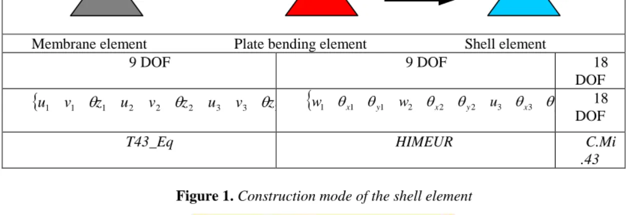
The present element is a flat plane thin shell element, obtained by superimposing the T43_Eq membrane finite element with the Himeur thin plate finite element. For the isotropic material case, we obtain his elementary stiffness matrix by adding the stiffness matrix of the membrane element to that of the inflectional element without coupling effect. We baptize him by C.Mi43. We outline the approach with his principles as follows: * We approximate the real geometry with flat planes (Figure 1), so we neglect the curvatures on the element. This avoids the membrane locking. * Use of a membrane element coupled to that of a plate-bending element (Figure 1). * The shell element may have any orientation in the global coordinate system XYZ (Figure 2). * We establish the passage of the local coordinates to the global coordinates through the rotation matrix [Ro]. * We rearrange the local rigidity terms (18x18) before assembly in the local level.
+
Membrane element Plate bending element Shell element
9 DOF 9 DOF 18 DOF
T z v u z v u z v u1 1
1 2 2
2 3 3
3
T y x y x y x w u w1 1 1 2 2 2 3 3 3 18 DOFT43_Eq HIMEUR C.Mi
.43
Figure 1. Construction mode of the shell element
Figure 2. The shell element relative to the local (his) and global coordinates
We lift the difficulty associated with the rigidity in θz in the formulation of the membrane element by introducing the rotation around the normal "drilling rotation" in the construction of the corresponding elementary stiffness matrix. 1 2 3 1 2 3 1 2 3
3. Validation.
To validate the present element, we use popular benchmark problems for static analysis of shells; and to compare it through the other element models in the literature, we examine a number of usually used standard problem that served the researchers to evaluate the performance of the finished shell elements.
3.1. Pinched cylinder with free edges problem.
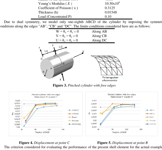
The pinched cylinder is a classical problem that used extensively to check the ability of shell elements to represent the in-extensional bending deformation. It has always served the researchers to evaluate the performance of the finished shell elements of convergence rate perspective and representation of rigid body motion. The test relates to the analysis of isotropic pinched cylinder with short free edges shown in Figure 3. The open-end cylinder leads to the pure in-extensional deformation at the limit as h/R approaches zero. For the present example, we have h/R=0,0031 and h/L=0,0015, indicate that the cylinder is very thin. Figure 3 shows the model geometry and mechanical data structure. The upload relates to the midsection of the cylinder by the application of two diametrically opposite forces (P) and (-P).
Length of the cylinder ( L ) 10.35
Radius of the cylinder ( R ) 4.953
Young’s Modulus ( E ) 10.50x10⁶
Coefficient of Poisson ( υ ) 0.3125
Thickness (h) 0.01548
Load (Concentrated P) 0.10
Due to dual symmetry, we model only one-eighth ABCD of the cylinder by imposing the symmetry conditions along the edges "AB", "CB" and "DC". The limits conditions considered here are as follows:
W = θx = θy = 0 Along AB V = θx = θz = 0 Along CB U = θy = θz = 0 Along DC
Figure 3. Pinched cylinder with free edges
Figure 4. Displacement at point C Figure 5. Displacement at point B
The criterion considered for evaluating the performance of the present shell element for the actual example is the displacement along the z-axis of the point C (displacement WC). We present at Figures 4 and 5 the results of our element and we conclude: - A rapid convergence of the present element, reflecting a correct representation of the state of rigid body motions, - Our element converge to the solution given by the deep shell theory WC = -0.0244 (thin cylinder case). - With the selected mesh, we observe a monotonic upward convergence of the present element. Numerical results for the pinched cylinder with open ends indicate that the proposed element exhibits a good accuracy.
3.2. Hyperbolic paraboloid shell under uniform pressure.
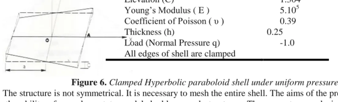
We consider a section of semi-thin hyperbolic paraboloid shell (2a/h=52) with embedded (clamped) straight edges subjected to a uniform normal pressure. We show the geometrical data and mechanical properties of the material in Figure 6.
Figure 6. Clamped Hyperbolic paraboloid shell under uniform pressure
The structure is not symmetrical. It is necessary to mesh the entire shell. The aims of the present example is to see the ability of our element to model double-curved structures. The present example is slightly dominant bending. We present the results of the study in the Figure 7. The figures characterize the deflection at the centre as a function of the total number of degrees of freedom for different meshes. We compare our results with the analytical solution given by Chetty and Tottenham [CHE 64] and with thus the numerical given by Guenfoud [GUE 90, 96] and by Bentaher [BEN 81]. We note a good non-monotonically convergence of the results of our element towards the analytical solution.
Figure 7. Displacement at the center of the shell 4. Conclusion.
The formulation of a flat triangular thin shell element with a true rotation based upon the strain approach has been successfully developed and presented in this communication. The three translational displacement (U, V, W) are each described in terms of cubic polynomial functions. The use of equal-order fields for all displacements has the effect of approximating further strictly the rigid body motion condition. The present formulation was demonstrated to be consistent in a very wide variety of linear analysis situations. A series of test problems were conducted to evaluate the efficiency of the element compared to other elements in the literature. The results obtained confirmed the fast convergence rate of the element. The proposed element has the advantage of being simple in form and uses the six degrees of freedom. Further, it can be used for the analysis of thin shell structures, even those with complex geometries
5. References
[HIM 15] Himeur, M., Zergua, A., & Guenfoud, M. (2015). A Finite Element Based on the Strain Approach Using Airy’s Function. Arabian Journal for Science and Engineering, 40(3), 719-733.
[HIM 14] Himeur, M., Benmarce, A., & Guenfoud, M. (2014). A new finite element based on the strain approach with transverse shear effect. Structural Engineering and Mechanics, 49(6), 793-810.
[HIM 11] Himeur, M., & Guenfoud, M. (2011). Bending triangular finite element with a fictitious fourth node based on the strain approach. European Journal of Computational Mechanics/Revue Européenne de Mécanique Numérique, 20(7-8), 455-485.
[HIM 08] Himeur, M. (2008). Développement d’éléments membranaires nouveaux d’élasticité plane basés sur la formulation en déformation (Doctoral dissertation, Thèse de magistère, Université de Guelma (Algérie), Département de Génie Civil.
Length ( 2a ) 12.92
Elevation (C) 1.304
Young’s Modulus ( E ) 5.105 Coefficient of Poisson ( υ ) 0.39
Thickness (h) 0.25
Load (Normal Pressure q) -1.0 All edges of shell are clamped