The Ducklingbot –
a Self-Driving Robot on a Pi
Zero
1
The Ducklingbot – a Self-Driving Robot on a Pi Zero
by Bethany A. LaPenta S.B. EECS MIT, 2014
Submitted to the
Department of Electrical Engineering and Computer Science In Partial Fulfillment of the Requirements for the Degree of Master of Engineering in Electrical Engineering and Computer Science
at the
Massachusetts Institute of Technology June, 2017
© 2017 Bethany A. LaPenta. All rights reserved.
The author hereby grants M.I.T. Permission to reproduce and distribute publicly paper and electronic copies of this thesis document in whole and in part in any medium now known or
hereafter created.
Author: __________________________________________________________ Department of Electrical Engineering and Computer Science
May 15, 2017
Certified By: ___________________________________________________________ Liam Paull, Research Scientist, CSAIL
May 15, 2017
Accepted By: ___________________________________________________________ Christopher Terman, Chairman, Master of Engineering Thesis Committee
2
The Ducklingbot – a Self-Driving Robot on a Pi Zero by Bethany A. LaPenta
Submitted to the Department of Electrical Engineering and Computer Science May 15, 2017
In Partial Fulfillment of the Requirements for the Degree of Master of Engineering in Electrical Engineering and Computer Science
Abstract
This paper describes a MEng thesis project conducted with the Duckietown group at MIT’s CSAIL. During the duration of the project, the Duckietown software suite and ROS was made to run on the Raspberry Pi Zero (Or Raspberry Pi Zero W) hardware. The chassis and size of the bot is scaled down from the original Duckiebot design. This reduced the cost for the robot. The smaller Duckiebot, called the Ducklingbot, provides insight as to how well the Duckietown software suite can scale downwards to a less-powerful system, as well as give those interested in working with Duckietown a cheaper entry point from the smaller hardware.
3
Acknowledgements and Thanks
Liam Paull, for taking up the role of supervisor and advisor for this thesis Andrea Censi, for providing mentorship and funding for the Ducklingbot My family, who have always been loving, supportive, and encouraging
4
Table of Contents
INTRODUCTION 7
THE IMPORTANCE OF AN ACCESSIBLE AUTONOMOUS VEHICLE PLATFORM 7
OVERVIEW OF THE DUCKIETOWN SOFTWARE AND HARDWARE 8
SETUP 9
SOLDERING THE DUCKIEBOT 9
CHASSIS ASSEMBLY 11
RASPBIAN CONFIGURATION, PART 1 14
RASPBIAN CONFIGURATION, PART 2 17
WHY INSTALLING ROS THROUGH APT-GET IS NOT A DUCKLING’S FRIEND 18
PREPARING DUCKIETOWN DEPENDENCIES 20
BUILDING AND COMPILATION OF ROS 21
(OPTIONAL) ALTERNATE SETUP: USING PRE-BUILT ROS 24
INSTALLING OPENCV 25
BUILDING DUCKIETOWN DEPENDENCIES, PART 1 27
BUILDING DUCKIETOWN DEPENDENCIES, PART 2 28
BUILDING DUCKIETOWN DEPENDENCIES, PART 3 30
SOFTWARE EXECUTION 30
SETTING UP A DESKTOP OR LAPTOP TO VIEW PUBLISHED TOPICS 30
GETTING CAMERA INPUT TO THE PI ZERO 31
RUNNING THE LINE DETECTOR FROM A ROS BAG 32
RUNNING THE LINE DETECTOR FROM A LIVE IMAGE 36
TROUBLESHOOTING 39
5
ANALYSIS 39
COST 39
SOLDERING 41
IMAGE PROCESSING SOFTWARE 43
PORTABILITY 46 PART ACCESSIBILITY 48 HARDWARE DIFFERENCES 49 FUTURE WORK 50 REFERENCES 52
6
Table of Figures
FIGURE 1 – MALE HEADERS AND A SOLDERED PI ZERO ... 10
FIGURE 2 – AN ASSEMBLED MOTOZERO ... 11
FIGURE 3 – A FULLY ASSEMBLED DUCKLINGBOT ... 13
FIGURE 4 – COMPRESSED IMAGE OUTPUT FROM A SAMPLE ROS BAG ... 34
FIGURE 5 – EXAMPLES OF LINE DETECTION OUTPUT FROM A ROS BAG. ... 35
FIGURE 6 – ADDITIONAL EXAMPLES OF LINE DETECTION OUTPUT FROM A ROS BAG ... 36
FIGURE 7 – EXAMPLE COMPRESSED LIVE CAMERA INPUT FROM THE PI ZERO ... 37
FIGURE 8 – EXAMPLE LIVE EDGE DETECTION FROM THE PI ZERO ... 38
FIGURE 9 – EXAMPLE LIVE COLOR SEGMENTATION FROM THE PI ZERO ... 38
FIGURE 10 – COST BREAKDOWN AND COAST ANALYSIS OF PARTS IN DUCKIEBOT AND DUCKLINGBOT ... 41
FIGURE 11 – EXAMPLE EDGE DETECTION FROM DUCKLINGBOT ... 44
FIGURE 12 – EXAMPLE EDGE DETECTION FROM DUCKLINGBOT ... 44
FIGURE 13 – EXAMPLE WALL OUTPUT FROM THE PI ZERO RUNNING LINE DETECTION ... 45
FIGURE 14 – TEMPERATURE OVER TIME AS THE PI ZERO RUNS ROS AND LIVE LINE DETECTION ... 46
FIGURE 15 – A PARTIALLY ASSEMBLED DUCKLINGBOT NEXT TO A FULLY ASSEMBLED DUCKIEBOT ... 48
7
Introduction
The Importance of an Accessible Autonomous Vehicle Platform The field of autonomy is a rapidly expanding industry, especially in the field of autonomous cars. In addition to research, consumer interest in level 3 and level 4 autonomous vehicles is also increasing, as well as a willingness to pay and additional $3300 for a level 3 vehicle, and $7253 for level 4 vehicles [3]. It is estimated that 75% of personal vehicles around the world will be autonomous-capable by 2035 [3]. With such an exciting and quickly growing field unfolding, it is important for interested students and aspiring engineers to be able to use a platform to learn how to use and improve on such a promising upcoming field. Duckietown is an open, inexpensive and flexible platform for autonomy education and research [1]. By providing access to a low-cost and flexible platform, students, researchers, and even children will have a chance to play with and explore this field. The flexibility of Duckietown is beneficial since it can entertain a wide range of individuals. Using the default configuration, a child can play with the Duckiebot, placing obstacles in front of it to watch how it responds, or simply observe the robot as it goes around a road. A student can examine the open-source code and learn further how it works, as well as study the8 algorithms and tools used to create the autonomy. A researcher will be able to expand on the platform by adding in their own contributions to the Duckietown platform, which evolves and grows over time with new features and alternative implementations. Duckietown already has established roots at universities around the world at Tsinghua University (China), National Chiao Tung University (Taiwan), MIT, Rensselaer Polytechnic Institute, and Rutgers University (US) [1]. However, the Duckiebot has room for cost reduction and improvement. The goal of the Ducklingbot is to reduce these costs by substituting parts from the Duckiebot with smaller, cheaper parts. The most notable change is the substitution from the Raspberry Pi 2 to the Raspberry Pi Zero. The Pi Zero trades some computation power for a lower cost and smaller form factor. The Pi Zero W includes a built in wireless chip will removes the need for an additional WiFi dongle. For the rest of this paper ‘Pi Zero’ will be used to refer to both the Pi Zero W and the Pi Zero, unless otherwise noted to be referring to a specific version, since the boards share many similarities and this project has been tested on both boards. Overview of the Duckietown Software and Hardware The Duckiebot has only one sensor – the camera. There are no wheel encoders, accelerometers, or other sensors. Since the Duckiebot depends fully and image and video processing, it is important to keep computation resources and limits in mind while writing software or adding components to the Duckiebot.
9
The Duckietown software is available for open-source contribution and downloads at the Duckietown Github, https://github.com/duckietown/Software. The suite runs with the Robot Operating System (ROS) Indigo version, and is mostly Python with a bit of C++. The Duckiebots are isolated, and do not communicate with each other over a private network, however, they may communicate to a laptop or computer through the use of ROS. As such, software and computation can handed of to a laptop or external device, and the Duckiebot will follow the commands given to it, but this is a suboptimal configuration since it has a hard dependency on the computer that it is tethered to and can be bottlenecked by the network speed. Thus the computation and processing is necessary to run on the Duckiebot itself to avoid delays in reaction. The Duckietown hardware can come in multiple configurations. From a bare-bones configuration that is essentially a camera, a Pi, wheels and a chassis, to a more luxurious ride for a Duckie that includes headlights and rear lights, a joystick controller, an individual network connection, and other features that could be added to the Duckiebot. This allows the hardware to scale with topics of interest for the child, student, or researcher.
Setup
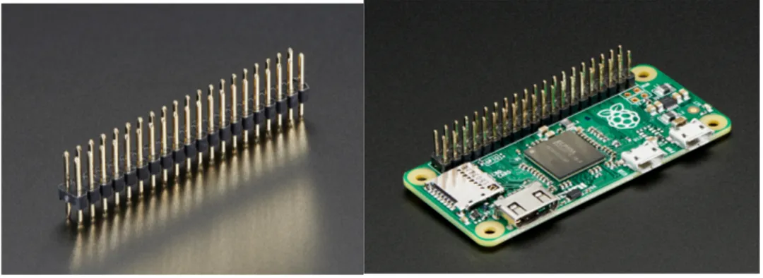
Soldering the Duckiebot10 Two components require soldering for the Ducklingbot. The Pi Zero and the MotoZero. The same soldering is needed for both the Pi Zero and the Pi Zero W boards. Solder a 2x20 male header to the GPIO pins of the Pi Zero. Be sure that pins are soldered in the configuration shown in figure [FIGURE], with the header pins sticking up from top of the board (The side with the Raspberry Pi Logo on it). If the pins are soldered upside down, the MotoZero board will not work correctly with the Pi Zero. Figure 1 – Male Headers and a Soldered Pi Zero Images from https://learn.adafruit.com/introducing-the-raspberry-pi-zero/gpio-header-options The soldering from the MotoZero is a bit more difficult. Full instructions for the soldering of this board is shown on the MotoZero website at https://cdn.shopify.com/s/files/1/0176/3274/files/MotoZero_User_Guide_1.2.pdf and it is highly advised to read and follow the instructions given on the official website to ensure proper configuration and use. Each component needs soldering on the MotoZero, and nothing comes pre assembled for this board. All of the components needed to stack the board onto the Pi Zero is included in the kit, however, so no extra parts (aside from a soldering iron and solder) are needed to ready the MotoZero for use.
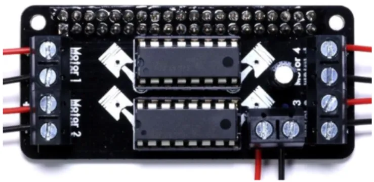
11 The final MotoZero will look like Figure 2 below. Note that this requires the soldering of two ICs, a header, and other low level components. Take caution while soldering this component, it is quite compact and easy to solder two pins together or make other soldering mistakes. The MotoZero is capable of controlling four separate motors, but the Ducklingbot uses only 2 motors. However, it is advised to solder all motor blocks for reconfiguration convenience or in the event of one of the motor blocks getting damaged. Figure 2 – An Assembled MotoZero (Image from the MotoZero Website) Chassis Assembly Assembly of the chassis is rather straightforward and will not be described in detail in this paper, as all the chassis kit itself will assist with the building of the base. A modification to note, however, is the addition of the upper square upon which the battery back, Duckie, and
12 camera sit. The additional metal square shown in the figure below was taken from another chassis kit, but can easily be substituted with any other platform, perhaps even a 3D printed platform. Various configurations can be used for the Ducklingbot depending on preference, but it should resemble the configuration in Figure 3 below.
13 Figure 3 – A Fully Assembled Ducklingbot
14 Raspbian Configuration, Part 1 The software side of the Ducklingbot is much more complex than the hardware. This paper will go into detail on how to reproduce the software setup. It is necessary to set aside an ample amount of time for the software to download, build, and install. There is a lot of idle time while the Pi Zero builds software, but it is not something that can be finished within a few hours. The installation guide provided here will assume basic knowledge of working with the Raspberry Pi, Linux, and ROS. The SD card should be set up with Raspbian. Unlike the Duckiebot, which runs Debian on the Pi 2, the Ducklingbot will run Raspbian on the Pi Zero. This set up requires an external computer. Depending on the operating system of the computer used for setup, directions may differ. Instructions in this thesis are provided for a Mac OS X setup, though other operating systems should have close similarities. First, Raspbian must be downloaded onto the computer that will be used to setup the SD card for the Pi. Raspbian can be found on the Raspberry Pi Website at https://www.raspberrypi.org/downloads/raspbian/. The “Raspbian Lite” image is needed, not the Pixel desktop which will install unnecessary desktop software. The Ducklingbot has been tested with the Jessie version of Raspbian, though other versions may work.
15 Second, the image will need to be installed onto the SD card. For Mac OS X, a useful utility that was used for this project is the Pi Filler application located at http://ivanx.com/raspberrypi/. This software is easy to use, it prompts what to do to easily and conveniently install Raspbian onto the SD card. After this has finished, the OS will be loaded onto the SD card and can be used to startup the Pi Zero immediately. However, It is very convenient to set up the Pi Zero OTG mode, which allows for SSH over USB. An easy method to set this up has been provided by the developer gbaman on the Github Gist platform [9]. The a short, paraphrased version of the setup will be reproduced below: • After installing Raspbian, open up the boot partition and add the line “dtoverlay=dwc2” to the “config.txt” file, then save it.
• Very carefully, edit “cmdline.txt”. Insert “modules-load=dwc2,g_ether” after “rootwait”
• Add a file named ‘ssh’ to the root of the SD card directory. It must not have an extension or contain any content.
• Remove the SD card and place it into the Pi Zero. Connect the Pi Zero to a computer via USB , wait a few moments for the Pi to start up, then open up a terminal. It should now be possible to ssh pi@raspberrypi.local The password, unless changed, should be the default value of “raspberry”.
16 If a Pi Zero W is not used, the network will need to be set up with the WiFi adapter of choice, consult the WiFi adapter user manual for drivers or other necessary components for the dongle. If a Pi Zero W is used, it is easy to add the network configuration to the Pi that will allow access to the Internet. • Edit the wpa file:
sudo nano /etc/wpa_supplicant/wpa_supplicant.conf
• Add the network credentials to the following, and paste it into the bottom of the file. Be sure to replace “WIFI NAME” and “WIFI PASSWORD” with the corrections needed for the nearby network. If there is no password, do not add the line that contains ‘psk’. network={ ssid="WIFI NAME" psk="WIFI PASSWORD" } • Edit the interfaces file:
sudo nano /etc/network/interfaces
This configuration is specific to each wireless network. However, for a basic dhcp network, the interfaces file should look like:
17
source-directory /etc/network/interfaces.d auto lo
iface lo inet loopback iface eth0 inet manual allow-hotplug wlan0 iface wlan0 inet dhcp
wireless-essid WIFINAMEHERE • Save the file and reboot the Pi, then ping a website to ensure connectivity. Now that the Pi Zero has access to the Internet, it is important to make sure that it is up to date. The following will show how to update the Pi Zero:
• sudo apt-get update
• sudo aptitude full-upgrade The Pi Zero is now ready to begin installing software needed to run Duckietown! Raspbian Configuration, Part 2 Some software packages are needed to finish installing and running the Duckietown software. They commands to install them are as follows:
• sudo apt-get install git • sudo apt-get install zip
• sudo apt-get install python-sip-dev
18 The Ducklingbot also needs increased swap space for building the software and for running the lane following and autonomous aspects. This is not ideal to do on an SD card, since the SD card will wear out over time and being used as swap space causes a lot of writes to the area. However, it is a necessity unless an external USB drive is provided as swap space. The following commands show how to increase the swap size.
• sudo nano /etc/dphys-swafile
• Edit the line that says “CONF_SWAPSIZE=100” and modify it to say
“CONF_SWAPSIZE=500”. This will increase swap space from 100mb to 500mb. Lastly, the camera must be enabled. • sudo raspi-config • Select option 5, Interfacing Options • Select P1 Camera, and then enable the camera. The board must then be restarted after these changes. Why Installing ROS Through apt-get is Not a Duckling’s Friend The Pi Zero uses the ARMv6 architecture due to its ARM1176 processor [7]. This is a different instruction set from the Pi 2’s ARMv8 architecture, which uses the ARM Cortex A53 CPU [6]. The Duckietown software had been previously only tested on a Pi 2, so the migration to a different architecture is something previously untested with the software suite.
19 Initially, the software needed (ROS and its package dependencies) was installed via apt-get, however, this did not work due to the chipset differences in the packages that apt-get provides, even the ARM Debian packages are not built on the correct architecture for the Pi Zero. The packages installed through apt-get that did not work were anything related to ROS, such as ros-indigo, ros-indigo-tf-conversion, ros-indigo-cv-bridge, and other ROS packages and dependencies.
Do not be tricked into going down this path! Everything will appear to be installing properly and working, the Duckietown software will eventually build, but there are inherent flaws in the build installed from apt-get. Running ‘roscore’ will cause the program to constantly crash and restart. There will be an error like the following, which repeats to infinity:
[rosout-1] restarting process
process[rosout-1]: started with pid [2239]
[rosout-1] process has died [pid 2239, exit code -4, cmd /opt/ros/indigo/lib/rosout/rosout __name:=rosout
__log:=/home/pi/.ros/log/3468f810-0c0b-11e7-a321-ca181f60c073/rosout-1.log]. log file: /home/pi/.ros/log/3468f810-0c0b-11e7-a321-ca181f60c073/rosout-1*.log
The log files are completely empty, and there is nothing very helpful to diagnose and debug this problem.
20 Another ROS command, rospack, will also provide an error. This error is much more useful and provides better insight as to what is going on. pi@raspberrypi:~/Software $ rospack Illegal instruction The illegal instruction command is evidence of an invalid build for a specific chipset, since the Pi Zero encounters an instruction that it is not sure how to handle on its current ARM architecture. Since the crucial ROS commands do not work on the apt-get build of ROS. As such, it is necessary to build ROS from source for the Raspberry Pi Zero. Previous projects have reported success of running ROS on a Raspberry Pi Zero, such as the robotic 3D printed snake created by H. Mohammed et all [4]. Thus it appeared that the Pi Zero could run the Duckietown software that depends on ROS. However, since installing directly out of apt-get did not work, it is necessary to fetch the software from an alternative method – by building it from source. Preparing Duckietown Dependencies Building ROS and running the Duckietown software depend on the Eigen software package and the OpenCV software package. Eigen is a quick setup, all that is required is to fetch the latest version of Eigen3 from the website at http://eigen.tuxfamily.org/, extract the files, and move it to the /usr/local/include directory. Eigen does not require any building or further setup, it is ready to use right out of the zip file.
21
OpenCV can be installed through the use of apt-get with the following command:
• sudo apt-get install libopencv-dev python-opencv
Fetch and run the modified duckiebot_img_creation.sh with the following commands:
• git clone https://gist.github.com/9e3804715b3671104b378bc60523bac3.git • cd 9e3804715b3671104b378bc60523bac3 • sudo sh duckiebot_img_creation_modified.sh Once these dependencies have been installed, building and installing ROS is now possible. Building and Compilation of ROS The following is a guide of how to setup and install the Duckietown software on the Raspberry Pi Zero. Installation of this was loosely followed from the official ROS installation guide, located at http://wiki.ros.org/indigo/Installation/Source, but needs a few extra steps for the Pi Zero. Since the Pi Zero is not extremely powerful, the process will take quite some time to build the software. While it is building software, the Pi Zero must be kept in a cool, open area. It will grow very hot during the build process. It is possible to destroy a Pi Zero from overheating (this had happened during one of the early trial runs of building ROS on the Pi Zero), so it is necessary to keep the Pi Zero cool during the build process. There is a faster option that allows the use of a custom, precompiled ROS build for the Pi Zero, see the optional section following this one that details how to skip the long
22 compilation stage. Do not follow this section if the alternate ROS installation method is used, only follow the next section. It is fine to use apt-get to install some initial dependencies of ROS. The following will provide an outline of how to get ROS running for Duckietown on a Pi Zero. Some of the steps are copied from the ROS source installation link provided above. More details on many of the steps below can be read on the ROS wiki, this will just provide a to-the-point install reference. 1) Make sure apt is up to date
• sudo apt-get update
2) Add the ROS repository to the Debian sources, then update apt
• sudo sh -c 'echo "deb http://packages.ros.org/ros/ubuntu $(lsb_release -sc) main" > /etc/apt/sources.list.d/ros-latest.list'
• sudo apt-get update
3) Fetch the dependencies of the build:
• sudo apt-get install rosdep rosinstall-generator python-wstool python-rosinstall build-essential
4) Initialize rosdep
• sudo rosdep init • rosdep update
5) Create a workspace to build out of. This path will need to be referenced in the future, so make note of it. ~/ros_catkin_ws has been chosen for this, but another path is also valid to use.
23 • mkdir ~/ros_catkin_ws • cd ~/ros_catkin_ws 6) Choose a ROS install. There are a variety of installation options for building ROS from source, as noted on the ROS wiki. Since the Pi Zero takes a long time to build and is quite small, installing the bare minimum is highly recommended. This setup has been tested on an 8GB SD card, so preserving space was desirable. As such, the ‘Bare Bones’ installation has been used.
• rosinstall_generator ros_comm --rosdistro indigo --deps --wet-only – tar > indigo-ros_comm-wet.rosinstall
• wstool init -j8 src indigo-ros_comm-wet.rosinstall
If running wstool init causes an error, the command can be resumed by running
• wstool update -j 4 -t src 7) Resolve any dependencies needed
• rosdep install --from-paths src --ignore-src --rosdistro indigo -y 8) Build it! This command will take many hours to build. Be sure that the Pi Zero is kept cool or it may break. • ./src/catkin/bin/catkin_make_isolated install -DCMAKE_BUILD_TYPE=Release 9) Source it, this will be added to a bash script later, but this is the command to do it. • source ~/ros_catkin_ws/install_isolated/setup.bash After some hours later, the Pi Zero should now have a working build of ROS! The build and installation can be tested by running ‘roscore’ and ‘rospack’, both of which should not throw errors (but will not do anything interesting at the moment).
24 (Optional) Alternate Setup: Using Pre-Built ROS Below details an alternate way to get ROS, using a pre-built workspace that was created for the Ducklingbot project. This will cut the setup time down drastically, but may not work on future versions of the Pi Zero. 1) Make sure apt is up to date
• sudo apt-get update
2) Add the ROS repository to the Debian sources, then update apt
• sudo sh -c 'echo "deb http://packages.ros.org/ros/ubuntu $(lsb_release -sc) main" > /etc/apt/sources.list.d/ros-latest.list'
• sudo apt-get update
3) Fetch the dependencies of the build:
• sudo apt-get install rosdep rosinstall-generator python-wstool python-rosinstall build-essential
4) Initialize rosdep
• sudo rosdep init • rosdep update 5) Get the built ROS catkin workspace from the following commands. This has been built with the bare-bones install package. • wget http://web.mit.edu/lapentab/www/ducklingbot/ros.zip • unzip ros.zip • cd ros_catkin_ws 6) Resolve any dependencies needed
• rosdep install --from-paths src --ignore-src --rosdistro indigo -y 7) Source it, this will be added to a bash script later, but this is the command to do it.
25
• source ~/ros_catkin_ws/install_isolated/setup.bash
ROS should now be working, test by running roscore. The command should run without throwing an error. Installing OpenCV The Duckietown software also requires the use of the OpenCV library. Again, using the apt-get repository does not work properly for the Pi Zero and the Duckietown software. The Duckietown software requires OpenCV to be in the /home/pi directory, and has a hard dependency on version 2.4.8 exactly. Another package that the Duckietown software depends on, however, requires the apt packages. It is a problem that version 2.4.8 is no longer available anywhere easily found, but has been nearly entirely replaced with version 2.4.9. This version will work, but requires some symbolic linking. This is a bit ‘hacky’, but it works for the intents of this project, and relaxing the dependency is non-trivial. There are multiple ways of going about solving this issue. The first is to build OpenCV by source. This takes an excruciatingly long time (approximately 9 hours) and will cause the Pi Zero to get very hot during this time. Building OpenCV from source is very involved will not be discussed in this paper, but instead a pre-built version of the software generated specifically for this project will be discussed instead, allowing future users to hopefully be able to skip the arduous step of building OpenCV by source!
26 1) Fetch the custom built version of OpenCV, place it in the /home/pi directory, unzip the file, and rename the folder to opencv: • cd /home/pi • wget web.mit.edu/lapentab/www/ducklingbot/opencv_core.zip • unzip opencv_core.zip (<- This step may take a while) • mv opencv_core opencv
2) Install the pre-built code
• cd opencv
• sudo make install
3) The OpenCV library also includes support for Java environments by default. However, to conserve space, the Java platform is not installed on the Pi Zero, and is not used in the Duckietown software at all. Thus, in order for the library to work without including Java dependencies, the cmake files must remove these dependencies from the list. The following steps will show how to modify this, but note that if OpenCV for Java is needed in the future, this step will cause it to not work. • rm –rf /usr/share/OpenCV (<- This may need to be run as root. Take care) • wget web.mit.edu/lapentab/www/ducklingbot/OpenCV.zip • unzip OpenCV.zip • mv OpenCV /usr/share/ 4) Lastly, the hardlinks must be set to link from version 2.4.8 that is required, to the version 2.4.9 that is installed. A shell script has been written to automate this, but will hopefully be unnecessary in the future if this hard requirement is relaxed. • wget web.mit.edu/lapentab/www/ducklingbot/hardlink.sh • sudo sh hardlink.sh
27
OpenCV should now be ready to go. The software has one more dependency, libpoco-dev which is dependent on OpenCV. The following will get it working.
• sudo apt-get install libpoco-dev (<- This may throw an error, that is ok) • sudo apt-get -f install
• sudo apt-get install libpoco-dev
The Duckietown Software should now be ready to build! Building Duckietown Dependencies, Part 1 Now that ROS has been setup on the Pi Zero, the Duckietown Software suite itself can be fetched and built. The first step is to pull the software from the Duckietown Github
• git clone https://github.com/duckietown/Software.git
Depending on network speed, this might take some time. If it seems like it has frozen or stopped responding, hitting enter will prompt a new updated line. If the updated line does not appear, and all of the numbers stop moving, it is possible that the Pi Zero had stopped responding, and a restart is necessary. It is then necessary to add the Ducklingbot to the scudera.yaml file. Since the Pi Zero defaults to the name raspberrypi.local, naming the robot ‘raspberrypi’ will cause it to work without further configuration. If multiple Ducklings are on the same network, they will need to be given unique local names and individually be added to the scudera.yaml file. Details on how to set up multiple Ducklingbots will not be given in this document.
28 Once adding the Ducklingbot to the scudera.yaml file, the environment can be setup. The environment script is different from the one used with the Duckiebots, so it is necessary to replace the environment.sh file with the one located at https://gist.github.com/lapentab/4ad4e2a6347b2618cc47670e9959dc0f. Once this has been done, it is possible to run the command: • source environment.sh When the machines file is created, it defaults to using the user ‘ubuntu’ as the login name. Unless the Pi Zero had been set up to have this login name (when ssh [username]@raspberrypi.local is used), it is necessary to update the machines file located at catkin_ws/src/duckietown/machines and change the user for the Ducklingbot. The line that contains the Ducklingbot’s name in the machines file will contain
user="ubuntu". This must be changed to user="pi" unless the login name had previously been changed. Building Duckietown Dependencies, Part 2 If the precompiled version of ROS for the Ducklingbot was used from above, it is not necessary to follow the following steps, as these dependencies have already been built and resolved in the prebuilt version. However, if ROS was built from source, it is necessary to build and install additional dependencies for Duckietown.
29 1) The first step is to create a new working directory in which to temporarily build the folders. • mkdir ~/dep_build • mkdir ~/dep_build/catkin_ws • mkdir ~/dep_build/catkin_ws/src • cd ~/dep_build/catkin_ws/src 2) Now, while within the source folder of the new catkin workspace, the new dependencies can be fetched from the web. There are quite a few, and should any dependencies change in future versions, their exact dependencies can be seen on the ROS website by visiting the url at http://wiki.ros.org/[PACKAGENAME], where [PACKAGENAME] is the name of the desired package. An example is the “angles” package, located at http://wiki.ros.org/angles. The sidebar lists the dependencies, for which only the base catkin is listed. As of the time of this paper, only the following dependencies are required.
• git clone https://github.com/ros/angles.git • git clone https://github.com/ros/geometry.git • git clone https://github.com/ros/geometry2.git • git clone https://github.com/ros/common_msgs.git • git clone https://github.com/ros/nodelet_core.git • git clone https://github.com/ros/class_loader.git • git clone https://github.com/ros/pluginlib.git • git clone https://github.com/ros/bond_core.git
• git clone https://github.com/ros-perception/vision_opencv.git • git clone https://github.com/ros/dynamic_reconfigure.git
30
3) After pulling the various packages, they must be built and installed to the ROS build. This will take some time to build, about 8 to 10 minutes. As always, the Pi must be kept in a cool location.
• catkin_make_isolated --install --install-space ~/ros_catkin_ws/install_isolated/ Building Duckietown Dependencies, Part 3 Finally, the Duckietown software itself can be built! Move to the catkin_ws folder of the Duckietown workspace, build the software, then run the rospack command to give ROS the ability to know the new sources. The following commands will accomplish the task: • cd ~/Software/catkin_ws • catkin_make • rospack profile This should again take some time, approximately 8 to 10 minutes, and then the Software side of the Ducklingbot has been fully configured!
Software Execution
Setting up a Desktop or Laptop to View Published Topics A separate computer with a GUI desktop is necessary to be able to visually see the images published from the Duckietown ROS environment. This desktop must have ROS Indigo installed. On the desktop or other computer, the ROS_MASTER_URI parameter must be set to
31
the IP address of the Ducklingbot. The ROS_IP must also be set to the other computer’s IP Address. If local domain resolution works, the following will suffice:
• export ROS_MASTER_URI=http://raspberrypi.local:11311/ • export ROS_IP=`hostname -I`
However, if raspberrypi.local does not resolve on the other computer, it will be necessary to use the IP of the Ducklingbot in the place of raspberrypi.local.
Running rviz or rqt_image_view can now be used to show the images that ROS publishes. Getting Camera Input to the Pi Zero The Ducklingbot is now able to receive and process camera input using ROS. After the Pi camera has been connected to the Pi Zero, the following commands will make it publish the camera input to a ROS topic.
The robot must first run roscore to start up a ROS master through which topics can be published to and subscribed from. This should be run in a screen so that it may persist through the rest of the execution. • screen • source ~/Software/environment.sh • roscore In a new screen created with ctrl+a+c, the camera_node can now be played and the topics published. • source ~/Software/environment.sh
32
The image will now be visible through rviz or rqt_image_view on the other computer.
Running the Line Detector from a ROS bag From the prior research and the class on Duckietown, there are a variety of pre-recorded inputs available for testing and simulation. Prior to configuring the Ducklingbot and calibrating it in a similar manner of the Duckiebot, testing was done to see how well the Pi Zero could run the basic tasks required for lane following. To test the lane following, a ROS bag was used that was recorded from a Duckiebot. The ROS bag camera input is looking around some of the roads of Duckietown. It contains camera inputs that have already been rectified from the fisheye lens, so it is ready directly for detecting lines and lanes. One of the bags tested is available in the following way: • cd ~/ • wget https://www.dropbox.com/s/8hizx7rfgj9jcqw/160122-manual1_ferrari.bag • mv ~/160122-manual1_ferrari.bag ~/test.bag The published topics during the ROS bag playback will continue to publish from the recording machine’s name, in this case, ferrari, unless the node is remapped. The main topic that is of interest to rename is the compressed camera output, located at
/ferrari/camera_node/image/compressed. This topic is used for a variety of the features in Duckietown, since it simulates the camera input of a live configuration. Remapping the publishing topic name is easy, however, and is able to done directly done during bag playback by assigning it with the standard ROS := assignment operator.
33
Again, a ROS master must be started on the pi via roscore. This should be run in a screen so that it may persist through the rest of the execution.
• screen
• source ~/Software/environment.sh • roscore
In a new screen created with ctrl+a+c, the bag can now be played and the topics published.
• rosbag play -l ~/test.bag
/ferrari/camera_node/image/compressed:=/raspberrypi/camera_node/image/c ompressed
After running this command, the robot will begin the playback of the contents of the bag. Since this bag has recorded camera inputs, it is now possible to view the compressed camera output through another computer running rviz or rqt_image_view.
34 Figure 4 – Compressed Image Output from a Sample ROS Bag The line detector node can now be run to see edge detection, colour mapping, and line outputs that the Duckietown software creates. While the ROS bag is still running from above, a new screen must be created and the software environment sourced. From there, the line detector can be started with the following command.
• roslaunch duckietown line_detector.launch veh:=raspberrypi live:=false verbose:=true
The live:=false parameter tells the launch file to not start up the camera instance. This is desired as the camera input will be simulated through the ROS bag output. Running rviz or rqt_image_view will now show additional published images: the edge detection, color segments, and lines. Sample images are shown in the figure below.
35 Figure 5 – Examples of Line Detection Output from a ROS Bag. Upper Right: Basic Compressed image. Upper Left: Color Segments. Lower Left: Edge Detection. Lower Right: Line Detection
36 Figure 6 – Additional Examples of Line Detection Output from A ROS Bag Upper Right: Basic Compressed image. Upper Left: Color Segments. Lower Left: Edge Detection. Lower Right: Line Detection Running the Line Detector from a Live Image In addition to running from a ROS bag, the Pi Zero is able to handle live input from the camera. It requires a similar setup from above, except with the camera connected and the live parameter to be set to true.
• roslaunch duckietown line_detector.launch veh:=raspberrypi live:=true verbose:=true
The software will now use live input from the camera, and can process the output in a similar manner to the processing of the bag file. Example output is shown below, with live images taken of Duckies.
37 Figure 7 – Example Compressed Live Camera Input from the Pi Zero
38 Figure 8 – Example Live Edge Detection from the Pi Zero Figure 9 – Example Live Color Segmentation from the Pi Zero
39
Troubleshooting
Troubleshooting and what to Look Out For On occasion, especially while using a Macbook Pro, the Pi will suddenly stop responding to the USB connection and all ping. The reason for this is most likely one or more of: a faulty USB connection cable, a faulty USB port on the computer or Pi, or overheating on the Pi. If the Pi Zero hangs, restarting it will solve the problem in most cases. As noted before, the Pi Zero has a tendency to get very hot when using computation intensive tasks. It is possible to destroy the Pi from heat. If the Pi Zero is not kept in a cool, uncovered environment while performing computational tasks, it may break permanently. The camera connector on the Pi Zero is extremely fragile. It must be handled with care and delicacy. Even presumably light motions can cause the adapter to snap off, rendering it broken and hard to keep the camera connector in contact with the board.Analysis
Cost The original hardware, the Duckiebot, is built mostly from parts available on Amazon and Adafruit. The Duckiebot requires a CanaKit Raspberry Pi 2 Starter Kit, for approximately $80, a stepper motor hat for approximately $20, and servo hat for approximately $20,40 battery kit for approximately $20, chassis for approximately $30, as well as other peripherals (Full list available in reference [2] – Step 0 – Buy the Parts) . The goal price of the Duckiebot is around $150, however, with the current prices of the parts, it can be well over $230. This cost is quite steep, as well as over the goal cost for the project. The Duckiebot is built with a Raspberry Pi 2, which is $40 if bought alone. In contrast, the Raspberry Pi Zero (or Zero W), is only $5 without built in wireless or $10 with built in wireless. Using the Pi Zero already cuts the cost by a large amount and is a very positive step in making the Duckietown platform more accessible to lower-income individuals.
Ducklingbot Part Cost Duckiebot Equivalent Cost Savings
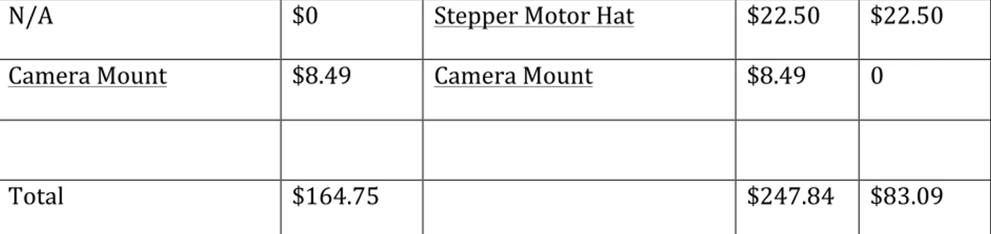
Pi Zero W Budget Pack $34.50 CanaKit Raspberry Pi 2 Starter Kit $79.99 $45.49 Raspbery Pi Camera Board V2 8 MP $29.95 Raspbery Pi Camera Board V2 8 MP $29.95 0 Mini Round Robot Chassis Kit - 2WD with DC Motors $19.95 Magician Chassis $29.95 $10 Battery $17.99 Battery $17.99 0 Fish Eye Lens $23.99 Fish Eye Lens $23.99 0 32 GB SD card $17.48 32 GB SD card $17.48 0 MotoZero Hat $12.40 PWM/Servo Hat $17.50 $5.10
41 N/A $0 Stepper Motor Hat $22.50 $22.50 Camera Mount $8.49 Camera Mount $8.49 0 Total $164.75 $247.84 $83.09 Figure 10 – Cost Breakdown and Coast Analysis of Parts in Duckiebot and Ducklingbot As seen in Figure 10, which lists the comparison of equivalent parts between the Ducklingbot and the Duckiebot, costs were reduced by over $80 for the Ducklingbot. Costs of shipping and handling were not factored into the raw part cost. For the cost analysis, shipping and handling costs are assumed to be closely equivalent between the Duckiebot and the Ducklingbot. An additional part can be used for the Ducklingbot, the Mini Robot Rover Chassis, which is $24.95. However, the only part used from this kit for the Ducklingbot is a small top square of metal that could be easily substituted out for a different, cheaper part that will hold the battery. Since this could be 3D printed or otherwise obtained for cheaper, the cost is not currently factored into the Ducklingbot. Soldering While the Ducklingbot shares many setup steps with the Duckiebot, it differs in a few ways. What the two bots share in common is a need of soldering. A main difference between what needs soldered, however, is the specific components. While the Pi 2 and Pi 3 can be purchased with headers already soldered on, the Pi Zero and Pi Zero W do not currently
42 have a purchasing option with headers at the time of this paper. Thus it is necessary for the user to solder headers onto all Pi Zeros purchased through normal avenues. For the Ducklingbot, Soldering is needed for both the Pi Zero and the MotoZero hat. The Pi Zero needs a 2x20 header soldered to the board, but the MotoZero hat requires the soldering of a 2x20 header, two integrated circuits (IC), a capacitor, and some terminal blocks. While soldering of the Pi Zero is fairly straightforward, the MotoZero soldering is a bit more involved. The Ducklingbot will need about 102 pins soldered plus some components. Those new to soldering and electronics may be daunted by this task. The Duckiebot, however, also requires soldering. Both the Stepper Motor hat and the PWM/Servo hat require soldering. These hats come already soldered with the relevant ICs and lower level circuit components. The only soldering required for these boards is two 2x20 headers, which is slightly easier to solder than soldering an IC, and overall will need about 80 pins soldered. Comparing the soldering differences between the Duckiebot and the Ducklingbot, the Duckiebot beats the Ducklingbot by a slight margin since the Duckiebot does not require the soldering of ICs, but the Ducklingbot does. However, the difference in difficulty is not too great and may not be a large factor for usability or accessibility.
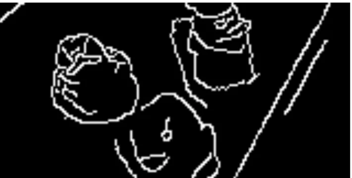
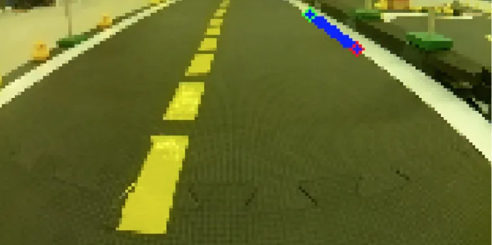
43 Image Processing Software The Duckietown software is computationally intense, since it must perform numerous transforms and calculations on the images to extract lines, edges, colors, normalization, and more. The software was built with the specs of the Pi 2 in mind, and had not been optimized to run on a Pi Zero. Unfortunately, the Pi Zero is unable to keep up with the processing power needed to usefully generate the line detections needed for lane following. The Pi Zero is only able to process about 5% of frames it receives during line detection, which leads to approximately 1 frame being generated per second. This is very slow for it to be able to run and adapt to a live environment to simulate a real self-driving vehicle. In addition to only processing one frame per second, the line detector node is only finding one or two lines per frame in an image, when there should be a multitude of lines. In the following figure, the full Duckiebot shows many lines in a similar scenario, whereas the Ducklingbot only shows one. This may be due to inadequate processing power on the Ducklingbot and its inability to finish processing frames in a timely manner.
44 Figure 11 – Example Edge Detection from Ducklingbot Note only one line processed and visible. Figure 12 – Example Edge Detection from Ducklingbot Note many lines processed and visible. Image from http://duckietown.mit.edu/media/collected.pdf
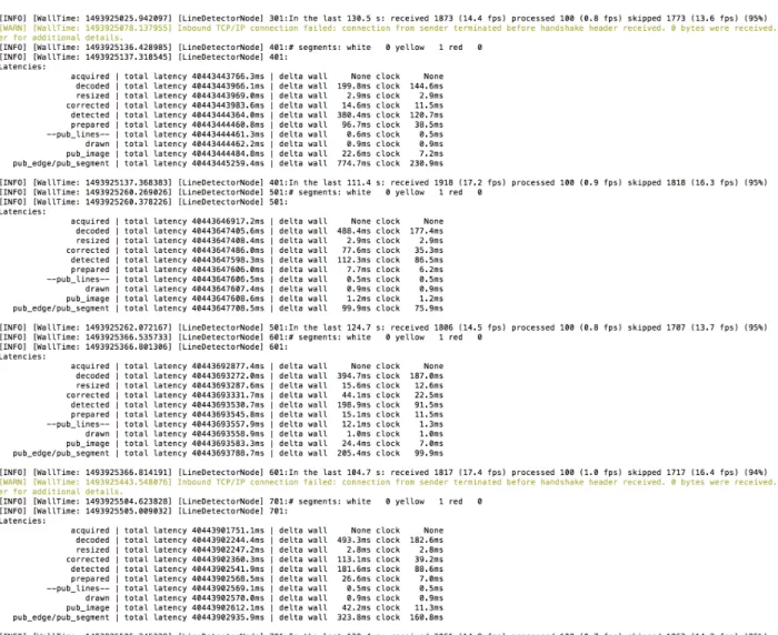
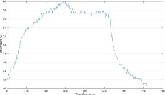
45 Example wall output from the Ducklingbot is shown below in Figure 13. It reports that it is only finding one segment through each time step, and is skipping many frames. Figure 13 – Example Wall Output from the Pi Zero running Line Detection The software also can cause the Pi Zero to greatly increase in temperature, seen in the figure below. The temperature was recorded in two 2 second intervals for the duration of the test, during which both roscore and live line detection. The processes were started quickly after starting the logging. The graph shows that the temperature increased by about 50% while these two processes were running, starting at approximately 40C at rest
46 and peaking at around 60C with the programs running. The programs were both terminated around 540s and the temperature quickly drops off as the Pi Zero cools. While this temperature is quite hot and additional ventilation and heatsinks for the Pi Zero would be advised, it is still within the operating temperature of the Pi Zero. Figure 14 – Temperature over Time as the Pi Zero runs ROS and Live Line Detection Portability The Ducklingbot has a very strong benefit for commenting students and researchers as it has a smaller profile and is easier to carry and transport around compared to the Duckiebot. During the trial run of the Duckietown Class at MIT in Spring of 2016, students were given boxes (Duckieboxes) with which to carry around their Duckiebots. Since the Duckiebots were needed for labs and demonstrations, as well as for work at home, they were carried to and from campus quite a bit.
47 The Duckiebots and Duckiebots were a bit unwieldy to carry, and were quite inconvenient to use in a classroom environment. Since the Ducklingbot is much smaller, it is easier to carry around and could perhaps even be placed in a protective box and put in a backpack or bag for transport. It is important to protect the Ducklingbot, so a box for transport would be necessary to prevent any parts from breaking or the bot from becoming disassembled. Hopefully the Ducklingbot will be more convenient for students to use and transport while also providing the functionality and learning experience that the Duckiebot and Duckietown provide. The dimensions of the Duckiebot are 6.5in x 5.2in x 6.0in, whereas the dimensions of the Ducklingbot are 4.2in x 3.9in x 5.0in, resulting in a 60% decrease in volume! This much more compact robot can be very convenient for the on-the-go autonomous vehicle enthusiast or researcher.
48 Figure 15 – A Partially Assembled Ducklingbot next to a Fully Assembled Duckiebot Part Accessibility The Ducklingbot is comprised of mostly easily purchased parts. The main part that might cause issue during purchase is the MotoZero hat- a necessity for the Ducklingbot. The MotoZero is only available through The Pi Hut website, which is based out of and only ships from the UK. For Non-UK based customers, there could be a long lead-time for purchasing
49 these parts (The website estimates approximately 25 working days for countries outside of the EU), which should be kept in mind when preparing the Ducklingbot for use in a classroom or research environment. The rest of the Ducklingbot can be purchased through a combination of Adafruit and Amazon with the exception of the fisheye lens required by both the Duckiebot and Ducklingbot. The MotoZero seems to be the only commercially manufactured option (at the time of this paper) for controlling motors with a Pi Zero. Aside from the international shipping and longer lead time, the MotoZero worked very well for controlling the motors for the scope of this project and would be recommended for use, though if alternatives become available they may also be tried. Hardware Differences Sending and receiving video and ROS data over the network was shown to cause network congestion when broadcast over the same network with a small fleet of Duckiebots, thus the Duckiebots had been equipped with their own personal hotspots [5]. For the Ducklingbot, adding a powered personal hotspot would require an external battery to power it. To reduce cost and profile, the Ducklingbot has not been equipped with a personal hotspot and it is recommended to avoid placing a group of Ducklingbots on the same network.
50
Future Work
As of right now, there is no central package for schools, researchers, or interested individuals to purchase a Duckiebot. The parts are largely dissociated among a variety of different websites, resulting in a confusing and disorganized ordering, setup, and inventory process. For convenience in the future, it would be beneficial to collaborate with an electronics hobby website to create a Duckling-in-a-Box kit that would contain everything needed to set up and get running with the Ducklingbot. This would make it easier for a person to get up and running with the Duckietown experience. A proposed kit would contain the motors, chassis, soldered motor hat, soldered Pi Zero W, a camera, the fisheye lens, battery, and necessary wires. Only basic non-soldering assembly would be needed for the setup of this Ducklingbot, and it could make the platform more appealing to a larger audience. Lastly, certain files would need to be written for ROS integration for the hardware that differs between the Duckiebot and the Ducklingbot, such as the motor controller for the MotoZero. The MotoZero was tested to work in an individual python file on the Pi Zero and was able to successfully get the wheels to move as desired, but full ROS integration has been left for the next iteration of the Ducklingbot. The Ducklingbot would also need a separate series of calibrations, since the Duckiebot camera is mounted at approximately 6 inches from the ground, whereas the Ducklingbot is mounted at approximately 5 inches51 from the ground. This height different would cause different perspectives that would need to be accounted for. Conclusion The results from the first generation of Ducklingbot have proven quite promising that the software can be run on the Pi Zero at all, opening up many potentials for future enhancements to this project. However, either the Duckietown software would need further optimizations, or the next iteration of the Pi Zero would need to be more computationally powerful for the Ducklingbot to be able to perform live lane following or other autonomous tasks in real-time. Nevetheless, the current state of the processing power is not unusable for simulations and testing. New features could still be added and tested on the Pi Zero in its current state, though may perform slower than on a Pi 2. Overall, the Ducklingbot has worked well as a proof-of-concept for porting the Duckietown software to the Pi Zero. Although computationally limited, the portability, cheaper price, and accessibility of the Ducklingbot have many benefits over the Duckiebot. Since the Rasperry Pi Foundation often releases more powerful and feature-rich boards, the future for the Ducklingbot looks bright.
52
References
[1] L. Paull, J. Tani et al. “Duckietown: an Open, Inexpensive and Flexible Platform for Autonomy Education and Research” submitted to ICRA 2017. [Online] Available https://drive.google.com/file/d/0B49dGT7ubfmSZFJmZEJwak5hcTQ/view [2] Duckietown Step 0 – Buy the Parts https://docs.google.com/document/d/1tRRN15MLBl5OwXkuhxToxqEZSDuvAlxXbi OygzJ4Guk/edit# [3] Prateek Bansal, Kara M. Kockelman, Amit Singh, Assessing public opinions of and interest in new vehicle technologies: An Austin perspective, Transportation Research Part C: Emerging Technologies, Volume 67, June 2016, Pages 1-14, ISSN 0968-090X, http://dx.doi.org/10.1016/j.trc.2016.01.019. (http://www.sciencedirect.com/science/article/pii/S0968090X16000383) [4] H. Mohammed, N. Gallardo, P. Benavidez, M. Jamshidi and B. Champion, "Design and control architecture of a 3D printed modular snake robot," 2016 World Automation Congress (WAC), Rio Grande, 2016, pp. 1-6. doi: 10.1109/WAC.2016.7583009 (http://ieeexplore.ieee.org/stamp/stamp.jsp?tp=&arnumber=7583009&isnumber= 7582944) [5] J. Tani, L. Paull et al. (2016) “Duckietown: an innovative way to teach autonomy”, submitted to EDUROBOTICS 2016. [Online]. Available: https://www.dropbox.com/s/8skjfd3f4kcv3wj/EducationalDuckietown.compresse d.pdf53 [6] "Cortex-A53 Processor” https://www.arm.com/products/processors/cortex-a/cortex-a53-processor.php [7] “ARM1176 Processor” https://www.arm.com/products/processors/classic/arm11/arm1176.ph [8] “Raspberry Pi” https://en.wikipedia.org/wiki/Raspberry_Pi [9] gbaman “Setting up Pi Zero OTG - The quick way (No USB keyboard, mouse, HDMI monitor needed)” https://gist.github.com/gbaman/975e2db164b3ca2b51ae11e45e8fd40a