Publisher’s version / Version de l'éditeur:
11th International Conference on Biocomposites: Transition to Green Materials,
2010-05-02
READ THESE TERMS AND CONDITIONS CAREFULLY BEFORE USING THIS WEBSITE. https://nrc-publications.canada.ca/eng/copyright
Vous avez des questions? Nous pouvons vous aider. Pour communiquer directement avec un auteur, consultez la première page de la revue dans laquelle son article a été publié afin de trouver ses coordonnées. Si vous n’arrivez pas à les repérer, communiquez avec nous à PublicationsArchive-ArchivesPublications@nrc-cnrc.gc.ca.
Questions? Contact the NRC Publications Archive team at
PublicationsArchive-ArchivesPublications@nrc-cnrc.gc.ca. If you wish to email the authors directly, please see the first page of the publication for their contact information.
NRC Publications Archive
Archives des publications du CNRC
This publication could be one of several versions: author’s original, accepted manuscript or the publisher’s version. / La version de cette publication peut être l’une des suivantes : la version prépublication de l’auteur, la version acceptée du manuscrit ou la version de l’éditeur.
Access and use of this website and the material on it are subject to the Terms and Conditions set forth at
New advancements on single fiber tensile test of natural fibers
Hu, Wei; Ton-That, Minh-Tan; Perrin-Sarazin, Florence; Denault, Johanne
https://publications-cnrc.canada.ca/fra/droits
L’accès à ce site Web et l’utilisation de son contenu sont assujettis aux conditions présentées dans le site LISEZ CES CONDITIONS ATTENTIVEMENT AVANT D’UTILISER CE SITE WEB.
NRC Publications Record / Notice d'Archives des publications de CNRC:
https://nrc-publications.canada.ca/eng/view/object/?id=11a058c6-e12b-4dc0-a317-9caf17b30d08 https://publications-cnrc.canada.ca/fra/voir/objet/?id=11a058c6-e12b-4dc0-a317-9caf17b30d08
11
thInternational Conference on Biocomposites:
Transition to Green Materials
New Advancements on Single Fiber Tensile Test of Natural Fibers
Wei Hu, Minh-Tan Ton-That, Florence Perrin-Sarazin, Johanne Denault
Industrial Materials Institute, National Research Council of Canada
Wei.hu@cnrc-nrc.gc.ca
Abstract
An improved Single Fiber Tensile Test (SFTT) for natural fibers was depicted. Natural fibers have irregular shape. They are not uniform along the fiber length, and also from one fiber to another. Applying the conventional SFTT method, which determine the fiber cross-section by measuring the fiber diameter using optical microscopy, result in inaccurate properties of natural fibers with large standard deviation (SD). In the proposed new SFTT method, an accurate cross-section area could be obtained from the Scanning Electron Microscope observation of a flat and clear fractured end surface of carefully selected tensile tested fibers and imaging analysis. Applying this new approach, tensile strength of different types of flax fiber, including bast fiber, enzyme retted and water retted fiber provided SD of less than 11%, while those of these fibers determined by the conventional approach had SD of over 24%.
1 Introduction
Natural fibers present the advantages of good mechanical properties, renewability, environmental friendliness and economical feasibility as reinforcements for polymer matrix composites [1]. Accurate and reliable measurement of the tensile strength of natural fibers by feasible technique thus becomes crucial for the comparison between different kind of fibers and also for the prediction of mechanical property of their composites.
Single fiber tensile test (SFTT) is the most widely applied method for the measurement of the tensile properties of fibers [2,3]. It is based on the diameter measurement to determine the cross-section area. While this method provides acceptable strength and modulus for synthetic fibers, it fails to provide accurate results with low standard deviation (SD) for natural fibers. Natural fibers are quite different from synthetic fibers. Natural technical fibre often consists
of a bundle of elementary fibers, which results in an irregular shape depending on the number of elementary fibers and the way which they are packed together. In addition, the cross-section of elementary fiber is not perfectly round, either. Thus, the fiber diameter observed under OM can vary a lot depending on the view it is observed. Furthermore, due to its irregular shape and its non-uniformity along the fiber axis, it is difficult to obtain a good focus on the fiber image under OM to determine fiber diameter.
In this paper, a new approach to measure the tensile properties of natural fiber was described. This improved SFTT involves modifications focusing on: 1) the selection of fibres for testing and 2) the accuracy of cross-section area determination of natural fibres. Flax fiber (F1) was used to validate the method and the results of the measurements are reported.
2 Experiments
F1 was kindly supplied by Schweitzer-Mauduit Company. A tensile machine Instron 5548 Microtester was used for tensile tests. Bausch & LOMB Optical Microscopy coupled with a COHU high performance color CCD camera was utilized for fiber selection. It was also used to help determine the cutting size in the cutting procedure, and fiber diameter with the aid of Visilog 5.4 software during conventional SFTT. A Reichert-Jung 2050 Supercut Microtome was used in the cutting procedure. JEOL JSM-6100 SEM working at a voltage of 10kV was utilized to select the good fracture end and determine the cross-section area with the aid of Image-pro Plus software.
2.1 Improved Method
2.1.1 Sample selection for testing
Firstly, single technical flax fibers without splitting were carefully selected by hand then by OM. Fibers with apparent defects should also be removed in this process if such defects are not representative for the
fiber nature. In addition, contaminated fibers would result in an obscured cross-section image thus introducing error on the determination of cross-section area. They should be removed, too.
2.1.2 Fiber tensile testing procedure
The single fiber tensile test was conducted according to ASTM D 3822-01 at room temperature. Tensile tests were performed on the carefully selected flax fibers. Both fiber ends were glued on a piece of tape, for easy handling and fastness on the grips. In this work, a grip length of 9 mm and a gauge length of 50 mm were used for testing. A translation speed of 120 mm / min was applied in all the tests.
2.1.3 Cross-section area determination
In order to determine tensile strength and modulus of the fibers, an accurate cross-section area must be obtained. Since fiber failure is very brittle and its elongation at break is very low (less than 2%), it can be considered that the cross-section area of the fiber at the failure location does not change significantly after failure. After testing, fractured fibers with appropriate fracture end were selected for the cross-section area calculation. This selection was done by microscopical observations to discard fracture end that split into fibril fibers, and keep brittle fracture end without splitting for the further cross-section area determination.
It is important to obtain a flat and clear cross-section of fiber fracture end to improve the accuracy of cross-section area. Therefore, the tested fiber was carefully attached on a tape, perpendicularly to the edge of the tape. OM coupled with Visilog 5.4 software was utilized to determine the distance between the edge of fiber fracture end and tape, thus to determine the optimum location at which the samples should be cut for a good presentation of the cross-section and also a clear image. To prevent the further movement of the fiber, it was fixed between 2 strong Polyethylene (PE) films (as supporting film). The edge of tape with fracture end and PE films end were tried to be placed on the same plane. A scheme of such arrangement is shown in Fig. 1 (a). The size of the PE films had to be fit to the mould. Then the sample was mounted with epoxy resin using the mixture of Epofix resin and Epofix hardener (Struers Company) with the ratio of 15 : 2 (v / v) at room temperature for 24 h. The scheme of such layout is given in Fig. 1 (b). Proper size of the PE films could prevent the sample moving in the epoxy liquid to avoid a tilted cross-section.
Figure 1. (a) The cross-section of the tip of the sample; (b) the layout of the sample moulded in epoxy mould
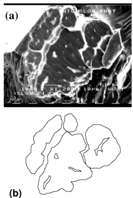
Figure 2. (a) SEM image of flat cross-section image after cutting procedure; (b) the boundary line of cross-section in (a) traced out using Adobe Photoshop 4.0 LE software
The embedded sample was finally microtomed according to the distance measured earlier by OM between the edge of tape and the fracture fiber end. More than one cut should be performed to ensure a good representation for the cross-section as necessary. Scanning Electron Microscope (SEM) was used to get
Double-side Glue Tape Fibre Supporting Film (a) Fracture End Supporting Film Epoxy Sample Fibre Glue Tape Microtomed Distance (b)
(b)
(a)
cross-section image of fiber fracture end (Fig. 2 (a)) with high accuracy.
From the SEM image the borderline of the cross-section was traced out using the Adobe Photoshop 4.0 LE software carefully. Fig. 2 (b) shows the corresponding boundary line obtained from Fig. 2 (a). Finally, the accurate value of total cross-section area could be obtained automatically using Image-pro Plus 4.5.1.27 software according to the borderline. The hollow structure (lumen) could be seen clearly in some elementary fibers as shown in Fig. 2 (a), however, their area could be ignored because it was at the most 1.5 % of the total area.
2.1.4 Calculating tensile strength and modulus
As the cross-section area of the fiber is determined and its corresponding force-elongation is obtained from the test, the tensile properties of the fiber can be easily evaluated according to the ASTM D 3822-01.
2.2 Conventional Method
The conventional method of diameter measurement for the calculation of cross-section area was carried out in comparison with the improved method on the selected samples (2.1.1). The diameter of 20 specimens was determined under OM before testing. The average fibre diameter at five different random locations on the fibre was applied to determine the diameter of fibre. The obtained diameter, D, value was utilized to calculate the cross-section area using equation of area = D2 / 4 for the final mechanical data analysis.
3 Results and Discussion
Excluding some slippage in the typical stress - strain curves (not shown here) of the F1 fiber from the tensile test at the beginning of the test, all tested flax fibres exhibited a linear elastic deformation until failure, and very brittle failure behaviour with minimum deformation of less than 2%.
3.1. Conventional SFTT
The average diameters, tensile strengths, modulus and strains of the F1 fibres including the SD values calculated from 20 specimens applying the conventional SFTT could be found in Table 1. It has been reported that the tensile strength and modulus of flax fibres are within the range of 345-1035 MPa and 27.6-80 GPa, respectively [1,4]. The reason for the lower strength value of F1 here was possibly due to
the oilseed type as well as growing area, climate factors and retting conditions. It was noticed that the SD in average diameter for a single fibre specimen was very high and over 40%, although specimens were carefully chosen for the test to limit effects of fibre non-uniformity and defects on results, and a large number of specimens were used aiming to reduce the SDs. The problem should be mainly due to the poor approach of fiber cross-section area determination. As it is reversely proportional to the diameter in a factor of power of 2 (σ = 4F / π D2
). A large error in diameter must lead to a great SD in strength and modulus. 3.2 Improved SFTT
Since fiber fracture is a brittle mode in the test (the spectra not shown here) and fiber strain at break is limited to 2% (Table 1), it can be assumed that the cross-section area after break does not significantly differ from that before fracture. Therefore, fiber cross-section area at the fracture location can be determined after the test. However, in some cases, due to the hollow structure of elementary fibers and the brittle nature of natural fiber, the fiber boundary can be deformed or split after mechanical test. Other researchers also reported the images of such cases for other kinds of natural fibers, such as hemp, sisal and abaca [5]. Thus it is too difficult to identify the boundary of the fibers. As a consequence, preparation of the fiber fracture end for observation as previously described is important. Because the elementary fibers are uniform along the fiber axis for a certain range (counting from the fracture end), it is expected that the cutting will not contribute significant error on the cross-section area determination. The good microtomy can provide a clear flat cross-section image of fiber facture end, as shown in Fig. 2 (a). The fiber cross-section area is the sum of the cross-cross-section areas of all elementary fibers consisted in the tested technical fiber and the voids in the center of the elementary fiber was also taken into account. The high magnification and resolution of SEM coupled with image analysis could enhance greatly the precision. As clearly seen, this method provides a most improved fiber cross-section area determination for the SFTT.
Table 1 shows the tensile strength, modulus and strain, and their SD values of F1 obtained from the improved method. The cross-section area was calculated from that described earlier. The strengths fail in the lower range of those reported in [1,4]. One significant result From Table 1 is SD. Although only 6 specimens were tested for each sample in this new method (while at least 20 specimens for the old methods), it provides sufficiently lower SDs, which is less than 15%. These
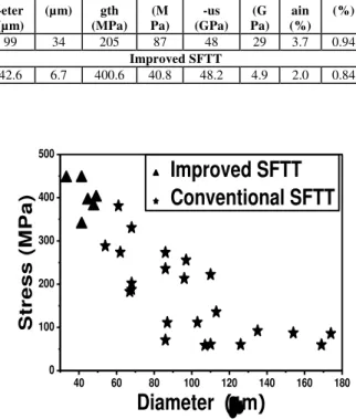
SD values were also much lower than those in the literatures [2,3], where the conventional method was applied for the calculation of tensile strength of natural fibers. Fig. 3 illustrates the improvement in accuracy and statistics of the improved SFTT method applying the average diameter value of 5 random locations along the fiber to calculate the cross-section area compared with the conventional method.
Table 1. Diameter, Tensile Strength, Modulus and Strain Values With SD Values Of Flax Fibres Obtained from Conventional SFTT
Method and Improved SFTT Method Conventional SFTT Diam -eter (µm) SD (µm) Stren-gth (MPa) SD (M Pa) Modul -us (GPa) SD (G Pa) Str-ain (%) SD (%) 99 34 205 87 48 29 3.7 0.94 Improved SFTT 42.6 6.7 400.6 40.8 48.2 4.9 2.0 0.84
Figure 3. The tensile stress as function of fiber diameter determined by both methods
4 Conclusion
An improved method to obtain more precise tensile strength and modulus of natural fibers was developed. This is based on the fine selection of the fibers and on the direct cross-section area measurement at the failure location. A more reasonable number of samples (around 6) needs to be tested to obtain reproducible
results. Efforts were focused on the fiber selection with good fracture end and on the procedure and techniques to prepare samples for the determination of the cross-section area at the failure point. Applying this new approach, the accurate tensile strength of bast flax was measured to be 400.6 ± 40.8 MPa, with the low SD of less than 11%. While tensile strength of these fibers determined by the conventional SFTT method presented SD of over 40%.
ACKNOWLEDGEMENTS
The authors acknowledge the Agriculture-Agri-food Canada for the funding via ABIP and NBP program and also the Biotechnology Research Institute of the National Research Council Canada and Schweitzer-Mauduit Canada for providing flax samples. Hu Wei thanks to the National Science and Engineering Research Council Canada for granting her a Postdoctoral Fellowship.
References
[1] Bledzki AK, Gassan J. Composites reinforced with cellulose based fibres. Prog Polym Sci 1999:24: 221-274.
[2] Park JM, Quang ST, Hwang BS, DeVries KL. Interfacial evaluation of modified jute and hemp fibers/polypropylene(PP) – maleic anhydride polypropylene copolymers (PP-MAPP) composites using micromechanical technique and nondestructive acoustic emission. Comp Sci Technol 2006:66:2686-2699.
[3] Zafeiropoulos NE, Dijon GG, Baillie CA. A study of the effect of surface treatments on the tensile strength of falx fibres : part I. application of Gaussian statistics. Composites Part A 2007:38:621-628.
[4] Li X, Tabil LG, Panigrahi S. Chemical treatments of natural fiber for use in natural fiber-reinforced composites: a review. J Polym Environ 2007:15:25-33.
[5] Baltazar-y-Jimenez A, Bistritz M, Schulz E, Bismarck A. Atmospheric air pressure plasma treatment of lignocellulosic fibres : impact on mechanical properties and adhesion to cellulose acetate butyrate. Comp Sci Technol 2008:68 :215-227. 40 60 80 100 120 140 160 180 0 100 200 300 400 500