III. ATOMIC RESONANCE AND SCATTERING
Academic Research Staff Prof. D. Kleppner
Prof. D. E. Pritchard
Graduate Students
J. Apt III E. M. Mattison W. D. Phillips
F. Y. Chu F. G. Walther
RESEARCH OBJECTIVES AND SUMMARY OF RESEARCH
Our interests center on the structure and interactions of atoms and molecules, and on their interaction with the radiation field. Our methods involve colliding beam scattering spectroscopy, atomic and molecular beam resonance spectroscopy, high-precision maser techniques and, more recently, optical fluorescence spectroscopy.
1. Hydrogen Maser Studies
We have measured the effect of nuclear mass on the magnetic moment of the bound electron by comparing the electronic g-factor in hydrogen and deuterium. Our experi-ments achieved a fractional accuracy of 3 X 10¹¹, and provide the first accurate verifi-cation of the quantum electrodynamic theory of the bound electron in an external field.
2. Production of a New Species of Molecule
We have succeeded in producing a molecular beam of the paramagnetic van derWaals molecule CsHg. Binding is provided through weak polarization forces, roughly 100 times smaller than chemical forces. CsHg represents only one of a large class of molecules which can be created, and which can yield information on atomic interaction mecha-nisms that cannot otherwise be observed.
3. Spin Exchange Scattering
We have carried out a detailed determination of the potential for an alkali and a molecule with nonzero electron spin. By measuring the spin dependence of the dif-ferential scattering cross section, we have been able to elucidate both the long- and short-range behavior of the K-0 2 system. Small-angle scattering results appear to be well described by elastic scattering theory, a rather
unexpected
result.4. Excited State Interactions
During the past year work was started on a program to measure coherence effects in excited atomic systems, and to study interactions between excited atoms. The initial effort is directed toward the production of nonradiating excited dimers.
D. Kleppner
This work was supported by the Joint Services Electronics Programs (U. S. Army, U. S. Navy and U. S. Air Force) under Contract DAAB07-71-C-0300, by the National Science Foundation (Grant GP Z8679) and the National Bureau of Standards (Grant 1-35857).
(III. ATOMIC RESONANCE AND SCATTERING)
A.
NUCLEAR MASS CORRECTION TO THE BOUND
ELECTRON g-FACTOR
There has been remarkable agreement between precise quantum electrodynamic (QED) calculations of fine and hyperfine structure in simple systems and experimental measurements. Recent theoretical work has extended high-order QED calculations to
hydrogenic systems in external fields for which precise experimental evidence is lacking. Grotch and HegstromZ have computed corrections to the electron g-factor, gj, in
one-2 3 2 2
electron atoms in an external field to relative orders a m/M, a m/M and a(m/M)2 including nuclear mass, and radiative and binding corrections. Comparison of their results with measurements of G = gJ(H)/gj(D) provides tests of both the nuclear mass-dependent correction terms and the reliability of quantum electrodynamic Zeeman the-ory. The theoretical result is
(G1
2
1
I)
t
m1
2 1
1
+21Ta3m,(
1
1
th=a me MD e - 2 2 e M M P M M D P = (7. 248-0. 026)X 109 -9 = 7. 222 X 10Previous experimental evidence is inconclusive. Hughes and Robinson3 found (G-1)HR = 7. 2(12) X 10 , in agreement with theory, while Larson, Valberg, and Ramsey4 found (G-1)LvR = 9.4(14) X 10 - 9, in disagreement with theory. These results are sensitive enough to test only the leading theoretical terms, and are slightly discrepant.
Our experimental result is (G-1) = 7. 22(3) X 10- 9, which confirms the leading
exp
theoretical term and gives us some confidence in the second and third terms, although the precision is not sufficient to resolve them clearly. Our result confirms the result of Hughes and Robinson, but disagrees with that of Larson, Valberg, and Ramsey.
The major factor contributing to the improved precision of our experiment (3 X 10-11
over that of the previous experiments (~l X 10- 9
) is that we measure the electron tran-sition frequencies in H and D simultaneously in the same spatial region. Since their g-factor ratio is essentially independent of the field, the problem of field stability, which previously limited the accuracy, is secondary.
1. Maser Apparatus
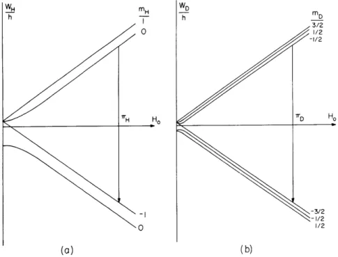
In our experiment we use a double-mode pulsed maser that radiates simultaneously on electron spin transitions H and D in ground state at a magnetic field of 3500 G. The energy levels are shown in Fig. III-1 with the observed transitions indicated by TH and
wD"
7'D Ho
(a)
(b)
Fig. III-1.
Atomic energy levels as a function of magnetic field:
(a) hydrogen; (b) deuterium.
RF DISCHARGE BULB
ORB- ION PUMP
DOUBLE-MODE MICROWAVE CAVITY H2 IN FACE diam. I- STATE- SE LECTI ON MAGNET BALL VALVE GLASS TUBE BULB
(b)
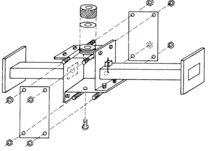
Fig. III-2. (a) Double-mode pulsed maser.
(b) Maser vacuum assembly.
QPR No. 104
LEAKS
(III. ATOMIC, RESONANCE AND SCATTERING)
Design and operating principles for the maser have been described elsewhere. 5' 6 Essentially, the maser produces a signal because of electron free-precession in a mag-netic field of 3500 G. Transition frequencies are typically 9. 5 GHz, and the decay time is 5 ms, corresponding to a resonance width of 70 Hz (Fig. III-2a).
The atomic beam is produced in a discharge bulb by RF dissociation of H-2 and D2
A standard hexapole focusing magnet state-selects the beam, which then enters a col-limated storage bulb within a microwave cavity. The storage bulb is coated with DuPont FEP-120 Teflon, which permits the atoms to make approximately 104 adiabatic wall collisions before the electron polarization is relaxed. The entire vacuum system is pumped by a Norton-NRC Orb-ion pump, rated at 800 1/s for air at high vacuum
(Fig. III-2b).
With the maser assembly resting securely on it, the entire magnet assembly floats on 4 air cushions to minimize vibration of the maser within the magnetic field. The magnet is temperature-regulated within a millidegree at ~34. 50C by two sensitive
thermal regulation controls, made up of thermistor bridge sensors, high-gain ampli-fiers, and proportional heaters. This system maintains field stability, with fractional drift rates typically less than 1 X 10⁻⁷ /h.
The magnet has mechanical pole adjustments for parallelism and lateral alignment, and standard Rose shims. With 19 electrical shims, we are able to achieve an rms field homogeneity of 1 X 10⁻⁷ over a spherical region 2. 5 cm in diameter.
The double-mode transmission cavity is resonant at 9200 MHz and 9650 MHz, which are the H and D transition frequencies, respectively (Fig. 111-3). The cavity operates in the TE102 and TE012 modes, with loaded Q's of ~4000. The modes can be tuned
102
012
(III. ATOMIC RESONANCE AND SCATTERING)
separately and can be simultaneously nearly critically coupled through simple wall irises.
2. Electronics
Because of the required frequency accuracy, all laboratory frequencies are derived in standard ways from a stable Sulzer crystal oscillator which is monitored against the NBS standard from WWVB by a VLF comparator. The oscillator is constantly main-tained to an absolute accuracy of 5 X 10 11; this results in a final error (6G/G)os c
3 X 10-12
03Xl0
S F E OR 001 ( SE)
MU PELOCKCK ] )
EN OR30 (IF MIXER)
MD FERATOR GET 31M.. (VOFH)
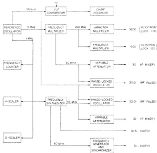
Fig. III-4. Frequency-generation scheme.
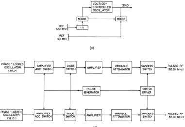
The frequency-generation scheme is shown in Fig. 111-4, the pulsed RF switching scheme in Fig. 111-5, and the microwave system in Fig. III-6a. One klystron (H) is phase-locked to a reference 9200 MHz, while the other klystron (D) is phase-locked to the first (Fig. III-6b). The atomic transitions are stimulated by "900 pulses," which enter the cavity through an under-coupled port and are generated by mixing pulsed RF power onto the microwave carriers in balanced modulators, with the resonance frequencies corresponding to the first sidebands of the respective carriers. The free-radiating signal power following the pulse is mixed with local-oscillator power from the klystrons in a microwave mixer-preamplifier circuit, thereby heterodyning the signals to intermediate frequencies corresponding (at resonance) to the respective pulsed radiofrequencies, 30.01 for H and 32.01 for D. The signals are then isolated and processed in the identical channels shown in Fig. 111-7.
VOLTAGE-CONTROLLED 01 OSCILLATOR MIXER MIXER REF 100 kH RE 30 MHz (a)
PHASE-LOCKED AMPLIFIER DIODE SAN PULSED RF
OSCILLATOR ' PULSED RF
(OSLL) AGC SWITCH SWITCH AMPLIFE ATTEMNUATOR SWITC 130.01 MM
AMPLIFIER DIODE VARIABLE SANDERS PULSED R OSCILLATOR AGC SWITCH SWITCH A TTENUATOR SWITCH (32.01 MHOI
(b)
Fig. 111-5.
(a) Phase-locked oscillator.
(b) RF switching networks.
IF SIGNALS 30.01.../32.01l..
S31...MHI PHASE KLYSTRON (H) VOFH DETECTOR REPELLER SUPPLY
31... 9200 M MIXER . LYSTRON REFERENCE (H) MIXER 9611... KLYSTRON 442. 400 MM I REFERENCE 42... 42.. PHASE KLYSTRON (D)
VOFH DETECTOR EPELLER SUPPLY
(b)
Fig. 111-6. (a) Microwave system.
(b) Klystron phase-locking
sys-tem.
IF SIGNALS
FROM MKROWRAE
MIXER AND PREAMPLIFIER
30.01/29.99 AND 52.01/31.99 VARIABLE I ~ RIABLE ATTENATOR AENUATOR (0-12 dB) (0-12 dB) IF AMPLIFIER IF AMPLIFIER 0oMMI 32 MH
REFERENCE MIXER MIXER REFEENCE
IO.. kHz I0.. kHz LOWPAGS LOWRASS
EROCROSS TRIGGER FRM ZEROCROSSING DETECTOR PULSE GENERATOR DETECTOR
ZERO-CROSSING BURST ZERO-CROSSING COUNTER CO UNTER COUNTER
START STOP START STOP
SCALER RESET SCALER AND READOUT START TRIGGER
TELETYPE SCANNER
COMPUTER ANALYSIS TELETyPE CONTROL PARAMETERS
ENTERED ON TELETYPE
PAPER
TAPE TO COMPUTER FOR PUNCM DATA REDUCTIONAND ANALYSIS /
Fig. 111-7.
Signal-detection and signal
processing channels.
--- ~
(III. ATOMIC RESONANCE AND SCATTERING)
PULSE VARIABLE DELAYED ARMING TRIGGER) The frequencies are determined by
mea-TRIGGER TIM DELAY (ENABLE) FROM
COUNT RESET) COTROL BURST COUNTER suring accurately the period of the residual
(C0 NTER 10-kHz signals. After filtering and
zero-2-DECADE TIRI NG START
SIOGAL F COM OUTER F STOP crossing detection, the signals (or "bursts")
DESFCTOR
are counted by circuits (Fig. III-8) that
gen-erate "start" and "stop" pulses at the first and
Fig. III-8.
Zero-crossing counter.th
(N+l)
t hzero crossings, thereby defining the
period of N cycles. These pulses then start
and stop scalers counting a reference 1-MHz signal. After accumulating a preset
num-ber of "bursts," the scaler counts are transferred by a teletype system to paper
display and punched paper tape for later computer analysis.
3.
Error Analysis
The systematic errors affecting this experiment have been analyzed thoroughly,7-9
and will be discussed fully as part of F. G. Walther's thesis research.
The major
sources of error are the inhomogeneity shift,
7spin-exchange pulling,
8the second-order
Doppler shift, wall shifts
9and instrumental pulling in the detection system.
The cavity
can be tuned sufficiently well to virtually eliminate cavity pulling, and many other
sources of error, which are always present, are small enough to be neglected.
We
remove the inhomogeneity shift by using several different collimators and extrapolating
to zero collimator length. Spin-exchange pulling has been extensively studied, with
cor-rections being made from computer integrations of the complete rate equations. Wall
shifts occur because of a change in hyperfine frequency during wall collisions.
These
effects are well-known and lead to a shift in G.
Instrumental effects are caused primarily by mixer distortion (phase shift vs
ampli-tude) and finite delay times in the counters, although bandpass pulling and leakage
power mechanisms are also present. Instrumental pulling, however, can be removed
by successively interchanging the -intermediate frequencies of H and D and by using
different sideband combinations of the IF carriers. All data are taken by using 4
dif-ferent sideband combinations; this provides two redundant means of removing
instru-mental pulling. Therefore we not only have data corrected for instruinstru-mental effects but
also a test of the consistency of the instrumental corrections.
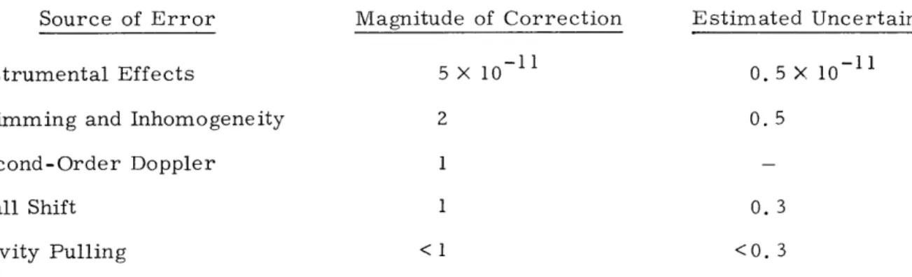
In Table III-1 important corrections to the raw data are listed, with typical values
given for both the total magnitude of the correction and the estimated uncertainty
asso-ciated with the correction.
Although three separate sets of data, after extrapolation to remove the
inhomo--11
geneity effect, agree within error bars of approximately 2 X 10
, we have some
evidence that other effects (presumably related to contaminated surfaces) can cause
shifts of several parts in 10
- 1 1 .Although the presence of these effects can be
QPR No. 104
~
--
rC
(III. ATOMIC RESONANCE AND SCATTERING)
Table III-1. Corrections to raw data.
Source of Error Magnitude of Correction Estimated Uncertainty
Instrumental Effects 5 X 10- 11 0.5 X 10⁻¹¹
Shimming and Inhomogeneity 2 0. 5
Second-Order Doppler 1
Wall Shift 1 0. 3
Cavity Pulling < 1 <0. 3
independently determined and apparently did not affect our final data, we have allowed -11
an additional 2 X 10 uncertainty for these effects to be added quadratically to our apparent error bar, which results in a final error bar of ~3 X 101 . Since some sub-jective judgment is included in this estimate, it should be viewed as our best estimate
of a 60% confidence interval.
F. G. Walther, W. D. Phillips, A. Jacobsen, D. Kleppner
References
1. S. J. Brodsky, Proc. International Conference on Precision Measurement and Fundamental Constants, Gaithersberg, Maryland, 1970.
2. H. Grotch and R. A. Hegstrom, Phys. Rev. A 4, 59 (1971).
3. I. G. Robinson and W. M. Hughes, Proc. International Conference on Precision Mea-surement and Fundamental Constants, Gaithersberg, Maryland, 1970.
4. D. J. Larson, P. A. Valberg, and N. F. Ramsey, Phys. Rev. Letters 23, 1369 (1969).
5. D. Kleppner, H. M. Goldenberg, and N. F. Ramsey, Phys. Rev. 126, 603 (1962). 6. P. F. Winkler, D. Kleppner, T. Myint, and F. G. Walther (to appear in Phys. Rev. A). 7. D. Brenner, Phys. Rev. 185, 26 (1969).
8. P. L. Bender, Phys. Rev. 132, 2154 (1963).
9. P. W. Zitzewitz, E. E. Uzgiris, and N. F. Ramsey, Rev. Sci. Instr. 41, 81 (1970).
B. MOLECULAR-BEAM STUDIES OF VAN DER WAALS MOLECULES: THE CsHg SYSTEM
We have produced and detected, for the first time, a free paramagnetic van der Waals molecule. The molecule CsHg has been produced and detected in a molecular beam.
2
(III. ATOMIC RESONANCE AND SCATTERING)
and we are searching for resonance transitions at low magnetic field.
Our goal is to
obtain information on atomic interactions and the structure of the weakly bound
mole-cules, especially about the spin-rotation coupling constant.
The formation mechanism
of these molecules in an atomic beam has been described previously.
1M' D'
S
MAGNET A
SLIT VELOCITY SELECTOR SLITSLIT
/ SM
D
)VEN POSITIONCsHg PATH
Cs
Cs
2('X)
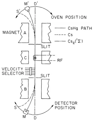
-RF DETECTOR POSITIONFig. 111-9. Schematic diagram of the apparatus.
Figure III-9 is a schematic diagram of the apparatus which was formerly used for spin-exchange scattering experiments, but has been demoted to a molecular-beam reso-nance machine by adding a C magnet and an RF coil. An oven with a 0. 00 18 in. con-verging nozzle, similar to one used by Gordon, is used to produce a supersonic jet. The oven is heated by 3 independent heaters in order to prevent clogging of the nozzle. A liquid-nitrogen-cooled housing with a water-cooled radiation shield is used to pump the large amount of Cs and Hg streaming from the oven. The skimmer has been elim-inated in order to prevent skimmer-jet interaction. Instead, a 0. 08 in. slit is situated approximately 1 in. downstream. The oven is loaded with equal amounts (by molar weight) of Cs and Hg and is operated typically at 750 K. A beam of Mach number 14 can be obtained with considerable enhancement of the association fraction of Cs dimers and CsHg molecules over that in the source.
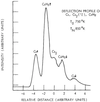
The beam contains Cs, Hg, Cs2 (1 2, 32), Hg2, CsHg, and other polymers of Cs and Hg. As the beam passes through the Stern-Gerlach magnet, the species are deflected
(III. ATOMIC RESONANCE AND SCATTERING) CsHgt DEFLECTION PROFILE OF Cs, Cs2('Z), CsHg
STO
7500K Csf Cs2 CsHg4z
Cs4 -6 -4 -2 0 2 4 6RELATIVE DISTANCE (ARBITRARY UNITS)
Fig. III-10. Deflection profile of the beam.
according to their weight and magnetic moment. (Unlike a thermal beam, all species of the jet beam travel at the same velocity.) Figure III-10 shows a profile of the inten-sity vs the source position with the detector fixed at positions M. A 2 X 10⁵/s maxi-mum flux of CsHg is detected, approximately a factor of 103 lower than the Cs flux.
The approximate Hamiltonian for the CsHg molecule in low magnetic field is
H = a I N + .- - gNN • H- gFBF - H,
where a and y are the hyperfine and spin-rotation coupling constants, N is the nuclear
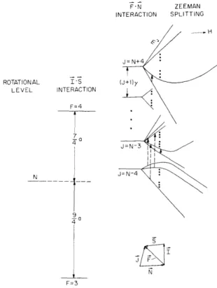
magneton, and B is the Bohr magneton. N is the rotational quantum number, and gN and gF are the nuclear and electronic g-factors. Figure III-11 is an energy-level dia-gram in low field; the possible transitions are indicated by arrows. The number of molecules in each quantum state is
n o
n 0 o p(n),
(2I+1)(2N+1)
where n is the initial flux, and p(n) is the probability of finding the molecule at ao -5 particular N. At a beam temperature of ~150K, n/no is ~8 X 10 . Since gN is dif-ferent for each state, the fraction of the beam contributing to a given transition is very small. A factor of eight increase in intensity can be obtained by using the state N = 4. At lower fields J = N + F is a good quantum number. For a AJ = 0, Am = ±1
(III. ATOMIC RESONANCE AND SCATTERING)
molecular-beam resonance transition (solid arrow)
gj oH Av = __ , h where J(J+l) + F(F+I) - N(N+1) 2J(J+1)
The state selector selects molecules with F = 4, and for N = 4. The fact that gj is inde-pendent of J and is equal to gF/2 allows simultaneous transitions in mj states for
F'N INTERACTION ZEEMAN SPLITTING ROTATIONAL IS LEVEL INTERACTION F=4 7 -0 N 7 9 4-0 F=3
Fig. III-11. Energy-level diagram and vector coupling model of CsHg. Solid arrow: AJ = 0, Am. = 1 transition.
J
Dotted arrow: AJ = 1, Am. = 0 low-field transition.
J
J = 8 to J = 1. The spin-rotational constant y can be deduced from the quadratic effect by observing the breakdown of N • F coupling as the magnetic field is increased.
An alternative way of observing the resonance is to use AJ = 1, Am = 0
J
QPR No. 104 gJ = gF
(III. ATOMIC RESONANCE AND SCATTERING)
transitions (dotted arrow) at very low field so that for a transition J = N - 4 - J = N - 3, we have
[g(J+l)-g(J)] 1oHm j/h < Av,
where Av is the resonance linewidth. If this condition is met, the transitions caused by all mJ states overlap. This method gives a direct measurement of y.
Our initial search has been hindered by a large background signal caused by the inability of the magnet to provide adequate separation of all the species. Large detec-tors and slit widths have aggravated this problem. Work is in progress to eliminate the background by narrowing the slit and detector. The new resonance machine described
in Section III-C should eliminate these problems.
F. Y. Chu, D. Kleppner, D. E. Pritchard
References
1. F. Y. Chu, D. E. Pritchard, and D. Kleppner, "Molecular Beam Studies of van der Waals Molecules," Quarterly Progress Report No. 100, Research Laboratory of Electronics, M.I.T., January 15, 1971, pp. 20-23.
2. R. J. Gordon, Ph.D. Thesis, Harvard University, 1969 (unpublished).
C. MOLECULAR-BEAM STUDIES OF VAN DER WAALS MOLECULES: NEW APPARATUS
In order to provide a more powerful and flexible facility for the study of van der Waals molecules, a new molecular-beam apparatus has been designed and is being built. Its basic structure is that of the traditional molecular-beam magnetic resonance machine: a source chamber containing the beam oven; a separately pumped velocity selector chamber; a magnet chamber with its own pump, containing two deflecting magnets ("A" and "B") and a homogeneous ("C") magnet with RF coil. A separate chamber containing a hot-wire detector is attached downstream of the magnet chamber.
The new machine will be superior to the present modified scattering apparatus in several respects. The high-temperature jet-beam oven will be provided with a gas inlet, so that, for example, alkali-rare gas van der Waals molecules can be studied. The increased pumping speed of the new apparatus, approximately 4 times that of the old, permits use of noncondensable gases.
The oven will have a separately heated skimmer, at an adjustable distance from the oven nozzle, so that beam conditions can be optimized. A water-cooled baffle will match the skimmer, minimizing scattering of condensable atoms into the beam.
(III. ATOMIC RESONANCE AND SCATTERING)
The deflecting magnets are twice as long (10 in.) as in the old apparatus, and are
designed to produce a field of approximately 22, 000 G, and a gradient of ~40, 000 G/cm.
The large deflection produced by these magnets will help eliminate the background of
unwanted atoms.
The C magnet in the new apparatus will be longer and more homogeneous than
4
that in the present machine, with a design homogeneity of better than 1 part in 10
.In
order to narrow the resonance line further, all of the magnets will be operated from
regulated power supplies, with the C magnet field-regulated by a nuclear magnetic
resonance probe.
F. Y. Chu, E. Mattison, J. Apt,
D. E. Pritchard, D. Kleppner
D.
SPIN-EXCHANGE SCATTERING
We have made measurements of the spin-dependent differential cross section in
scat-tering of K from 0
2at thermal energies, and have obtained from this the probability
of spin exchange during a collision, P ex(0), and the spin summed differential cross
section, ,sum (),
both as functions of energy and angle.
The data were then analyzed
with the aim of determining the intermolecular forces.
For elastic scattering, the interaction is described by two potentials, depending
on the spin state of the KO
2"molecule," doublet or quartet.
The long-distance
van der Waals attraction is expected to be spin- independent; and at small
intermolec-ular distances both states are repulsive.
In the intermediate range of ~8-15 a
o ,electron cloud overlap is expected to cause repulsion in the quartet state and increased
attraction in the doublet state, so that the average of the two potentials still follows the
van der Waals potential.1
In the following equations, asum is a weighted average of the scattering from the two
potentials and Pex depends on the interference between the two scattering amplitudes
Ssum(0) =[4
(0
2
24)4
f4()-f 2(0)P ex
ex
( 6 ) -2727
()
sum
where f
2f4'
2' 04 are the scattering amplitudes and cross sections for doublet
and quartet scattering.
The cross sections were calculated from the usual partial wave expansion by
using a 7-parameter model for the derivative of the phase shift with respect to the
angular momentum.
For the derivative of the phase shift we chose a model that is
(III. ATOMIC RESONANCE AND SCATTERING)
closely related to the deflection function. This model can easily be varied to produce a desired change in the cross section. In the semiclassical approximation,
X(b) = 2 a lC=kb
where X(b) is the classical angle of deflection as a function of the impact parameter b, rl(f) is the phase shift of the kt h
partial wave, and k is the wave number, k = (2mE) 1/2/1. The potential can be calculated from the deflection function, although we
2 have not carried out that calculation.
For small-angle scattering, "sum is dominated by o4 so that we need only consider
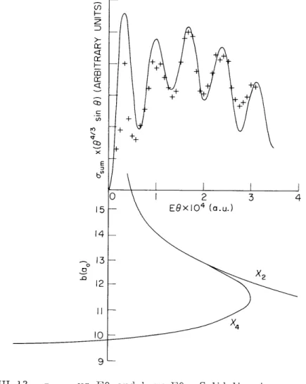
co I-M
-rIr
X, EFig. 111-12. usum vs EO and b vs EO. Solid line in -sum plot is calculated from a given deflection function. Crosses are data points. Vertical scale of sum is arbitrary and chosen so that the data points approximately coin-cide with the calculated cross section.
(III. ATOMIC RESONANCE AND SCATTERING)
the quartet scattering in describing-the features of
a
sumr
The position of the broad
peak in a-
sum corresponds roughly to the maximum angle of classical scattering caused
by the attractive branch of
the
deflection function, the rainbow angle (Fig. I1-12). The
oscillations are caused by diffraction effects, and their period near a particular position
gives a direct measure of the distance between the impact parameters corresponding to
that angle of scattering.
Figure
III-12
shows the experimental and calculated sum cross sections and the best
fit to the deflection function.
These selected data exhibit the clearest structure, but
other data taken at different energies and out to larger angles can be reproduced equally
well by using the fact that EX(E, b) is independent of the energy, E, to find X(E, b) at
the different energies.
(The deflection for a given impact parameter can be shown to
be inversely proportional to the energy for small angles of deflection.
3)
The
experi-mental and calculated probability of exchange are given in Fig. 11-13.
It should be
noted that the rapid oscillatory structure which was present in the calculation is averaged
away in the data at the larger angles chiefly because these data were averaged over a
range of velocities.
The requirement that the calculations reproduce -sum within experimental error
fixes the rainbow angle within 10%/,
the impact parameter, b
g,
at which the deflection
function crosses X
=
0 within
2%,
and the phase at b (or, equivalently, the integral of
0.7-
0.6-0.5
0.4
0.3
+
0.2 + + + +0.1
+ 0 I 2 3 4 5 6 7 8 9EO
x -4 (a.u.)Fig. 111-13.
P vs EQ. Solid line isex
Crosses are data points.
calculated.
(III. ATOMIC RESONANCE AND SCATTERING)
the deflection function from bg to infinity) within 10%. But 0-sum is relatively insensitive to the shape of the deflection function near its minimum and to the long- and short-range interactions for b > 15 a or b < 10 a
o o
To fit P ex' another constraint must be put on the calculated deflection function. For 1
small scattering angles, the requirement that the average of the doublet and quartet potentials be the van der Waals potential implies that the same is true for the deflec-tion funcdeflec-tions. The value of Pex (0) with its oscillations removed by averaging deter-mines the difference between the deflection functions and therefore the difference between each one and the van der Waals potential for angles less than the rainbow.
With this information about the shape of the deflection function near its minimum, and the information from
usum'
the calculated deflection function should be accurate within 20% between 10 a and 15 a . At the minimum it should be accurate to 10% ando o
outside this range to 50%.
There are two important results of this work. The first is the determination of the quartet and doublet deflection functions for the KO2 system; these may be inverted to give the long-range behavior of the intermolecular potentials for KO2. This is, as far as we know, the first detailed determination of the potential between an alkali and a molecule with nonzero electron spin. The second result is that the small-angle scattering in this system can be described fully by simple elastic scattering. This is somewhat surprising, since we know5 that the wide-angle scattering is dominated by complex formation: K + 02 - KO2 - K + 02, where KO2 indicates an autodisso-ciating state of the KO 2 molecule.
J. Lacy, D. E. Prichard References
1. D. E. Pritchard and F. Y. Chu, Phys. Rev. A2, 1932 (1970). 2. G. M. Carter and D. E. Pritchard (submitted to Phys. Rev.).
3. W. H. Miller and H. Kruger, Phys. Rev. Letters, 28A, 165 (1968).
4. F. T. Smith, R. P. Marchi, and K. G. Dedrick, Phys. Rev. 150, 79 (1966). 5. D. O. Ham, Ph.D. Thesis, Department of Chemistry, M. I. T., February 1968
(unpublished).
E. NONRADIATING EXCITED COMPLEXES
The long-range interaction between two atoms is generally the second-order van der Waals interaction -C/r 6 , but the interaction between identical atoms, one of which is excited, is first-order, D/r 3 . This well-known effect, resonant dispersion
interaction, plays an important role in the long-range potential of excited dimers. These excited complexes possess interesting radiative properties; essentially, they provide the simplest example of a two-body coherent system. Therefore the complexes are an
(III.
ATOMIC RESONANCE AND SCATTERING)
ideal subject for use in investigating the properties of simple super-radiant systems.
The origin of resonant dispersion energy can be seen by the following simple
argu-ment.
Consider two identical L-C circuits with resonant frequency
wo
= (LC)
/2
.The
energy of each oscillator is (n+l/2)hcoo, where n is the photon occupation number.
If
the oscillators are in the ground state, the energy is
1
1
E
hw +
ohE
c= -
hw
Now let the oscillators interact by electric coupling of the fringe fields of the
capaci-tor.
If the coupling coefficient is
K,then the resonant mode is split into two modes
having frequencies
o : l± + K. o O
The energy is
E
o'
=
2o1
o-For
K<< 1, the change in energy because of interaction is
1
2Z
AE = E' - E = - K .
o o o 4 o
The capacitors couple like two dipoles, and
Kl/R
3,
where R is the separation
of the circuits. Hence AE
= -C/R
.
This is the lumped oscillation analog to the
van der Waals attraction between atoms.
Next, assume that one of the oscillators is excited with one photon.
Then
3
1
12
o
2
0The interaction energy for
K<< 1 is
El =-mo {T4± K-K2
The change of energy, to lowest order of
K,is
1 3
AE =± h 0 K = ±D/R
1
2
o
where D is a constant.
The sign of the interaction is positive if the system is in a
sym-metric mode, negative if the mode is antisymsym-metric.
If the photon is localized on one oscillator, the system has mixed symmetry and the
(III. ATOMIC RESONANCE AND SCATTERING)
first-order interaction is zero. A system prepared in a state of pure symmetry, how-ever, has a large, first-order, interaction.
The lifetime of an excited molecule bound in the symmetric state by first-order dis-persion forces exhibits the shortening associated with a super-radiant system; in this case the lifetime is one half the free-atom lifetime. The antisymmetric state, however, behaves quite differently; it exhibits what might be called "super nonradiance. " Essen-tially, the radiating dipoles of the two atoms are out of phase, and the total dipole is
zero.
The radiation theory for two identical atoms and one photon has been attacked the-oretically by Stephen1 and others,2-5 but until now these systems have not been inves-tigated experimentally.
We are attempting to produce nonradiant excited complexes of two sodium atoms. The complexes will be formed by exciting the forbidden transition, and observed by the delayed fluorescence rate. The initial work is being carried out in a gas cell, although the use of high-intensity atomic beams would have some advantages. We have con-structed a flashlamp pumped dye laser and much of the photon-counting equipment.
R. Bailey, C. Wieman, D. Kleppner References
1. M. J. Stephen, J. Chem. Phys. 40, 699 (1964). 2. E. A. Power, J. Chem. Phys. 46, 4297 (1967).
3. P. R. Fontana and D. Hearn, Phys. Rev. Letters 19, 481 (1967). 4. R. H. Lehmberg, Phys. Rev. A 2, 889 (1970).