Publisher’s version / Version de l'éditeur:
Vous avez des questions? Nous pouvons vous aider. Pour communiquer directement avec un auteur, consultez la première page de la revue dans laquelle son article a été publié afin de trouver ses coordonnées. Si vous n’arrivez pas à les repérer, communiquez avec nous à PublicationsArchive-ArchivesPublications@nrc-cnrc.gc.ca.
Questions? Contact the NRC Publications Archive team at
PublicationsArchive-ArchivesPublications@nrc-cnrc.gc.ca. If you wish to email the authors directly, please see the first page of the publication for their contact information.
https://publications-cnrc.canada.ca/fra/droits
L’accès à ce site Web et l’utilisation de son contenu sont assujettis aux conditions présentées dans le site LISEZ CES CONDITIONS ATTENTIVEMENT AVANT D’UTILISER CE SITE WEB.
Client Report (National Research Council of Canada. Construction), 2014-12-31
READ THESE TERMS AND CONDITIONS CAREFULLY BEFORE USING THIS WEBSITE.
https://nrc-publications.canada.ca/eng/copyright
NRC Publications Archive Record / Notice des Archives des publications du CNRC :
https://nrc-publications.canada.ca/eng/view/object/?id=e9340acd-556e-4800-8028-745e724aa2e8 https://publications-cnrc.canada.ca/fra/voir/objet/?id=e9340acd-556e-4800-8028-745e724aa2e8
NRC Publications Archive
Archives des publications du CNRC
For the publisher’s version, please access the DOI link below./ Pour consulter la version de l’éditeur, utilisez le lien DOI ci-dessous.
https://doi.org/10.4224/21274564
Access and use of this website and the material on it are subject to the Terms and Conditions set forth at
Solutions for mid-rise wood construction: apartment fire test with
encapsulated cross laminated timber construction: Test APT-CLT:
report to Research Consortium for Wood and Wood-Hybrid Mid-Rise
Buildings
NATIONAL RESEARCH COUNCIL CANADA
REPORT TO RESEARCH CONSORTIUM
FOR WOOD AND WOOD-HYBRID
MID-RISE BUILDINGS
Solutions for Mid-Rise Wood Construction:
Apartment Fire Test with Encapsulated
Cross Laminated Timber Construction
(Test APT-CLT)
CLIENT REPORT: A1-100035-01.10
December 31, 2014
REPORT TO RESEARCH CONSORTIUM FOR WOOD AND
WOOD-HYBRID MID-RISE BUILDINGS
Solutions for Mid-Rise Wood Construction:
Apartment Fire Test with Encapsulated Cross Laminated Timber
Construction (Test APT-CLT)
B.C. Taber, G.D. Lougheed, J.Z. Su and N. Bénichou
Report No.
A1-100035-01.10
Report date: December 31, 2014
Contract No. B-7000 (A1-100035)
Prepared for Canadian Wood Council
FPInnovations
Régie du bâtiment du Québec
HER MAJESTY THE QUEEN IN RIGHT OF ONTARIO as represented by
the Minister of Municipal Affairs and Housing
104 pages
This report may not be reproduced in whole or in part without the written consent of both the client and the National Research Council of Canada
TABLE OF CONTENTS
Contents
1 Introduction ...1
2 General Test Arrangement ...2
3 Structural Assemblies (Middle Storey)...5
3.1 Wall Assemblies...5 3.1.1 Wall Type A ...5 3.1.2 Wall Type B ...6 3.1.3 Wall Type C ...7 3.1.4 Wall Type D ...7 3.2 Floor/ceiling Assemblies...8 4 Lowest Storey...9 5 Highest Storey...10 6 Structural Loading ...10 7 Fuel Load ...13 8 Instrumentation...14
8.1 Thermocouple Trees in the Middle Storey (Fire Floor)...14
8.2 Thermocouples in Wall Assemblies...15
8.3 Thermocouples in Ceiling/Floor Assemblies ...15
8.4 Surface and Interface Temperatures ...16
8.5 Thermocouples in the Highest Storey...17
8.6 Additional Thermocouples ...18
8.7 Heat Flux Meters. ...18
8.8 Duct Measurements ...19 8.9 Video...19 8.10 Smoke Alarm...19 9 Ventilation ...21 10 Ignition Scenario...22 11 Results ...23
11.1 Temperatures in Simulated Apartment ...23
11.1.1 Bedroom Temperatures ...23
11.1.2 Living Room/Kitchen and Entryway Temperatures...25
11.1.3 Summary Temperatures in Simulated Apartment...27
11.2 Temperatures in Wall Assemblies ...30
11.2.2 Bedroom/Bathroom Partition with Regular Gypsum Board...31
11.2.3 Interior Bedroom/Living room Wall...31
11.2.4 North Exterior Wall...33
11.2.5 East Living Room/Kitchen Wall ...34
11.2.6 South Corridor Wall...35
11.2.7 Interface Temperature Profiles in West Bedroom Wall...36
11.2.8 Temperatures Measured on Unexposed Side of West Bedroom Wall...38
11.2.9 Temperatures Measured on Bedroom and Corridor Entryway Doors ...38
11.2.10 Temperatures in Joint between CLT Panels in West Bedroom Wall...38
11.2.11 Summary of Temperatures in Wall Assemblies...39
11.3 Temperatures in Ceiling Assembly ...54
11.3.1 Ceiling Assembly in Bedroom ...54
11.3.2 Ceiling Assembly in Living Room/Kitchen Area...54
11.3.3 Interface Temperature Profiles in Bedroom Ceiling Assembly...55
11.3.4 Temperatures in Joint between CLT Panels in Bedroom Ceiling Assembly ...56
11.3.5 Temperatures Measured on Unexposed Side of Ceiling Assembly above Bedroom ...57
11.3.6 Summary of Temperatures in Ceiling Assembly...57
11.4 Temperatures in the Floor Assembly of the Fire Floor ...66
11.4.1 Floor Assembly in Bedroom...66
11.4.2 Living Room/Kitchen Floor Assembly Unexposed Side...67
11.4.3 Unexposed Side of the Bedroom Floor/Ceiling CLT Panels ...67
11.4.4 Interface Temperature Profiles in Bedroom Floor Assembly ...68
11.4.5 Summary of Temperatures in Floor Assembly ...69
11.5 Temperatures Measured in the Highest Storey...77
11.6 Heat Fluxes to the Exterior Wall Façade...79
11.7 Heat Fluxes from the Openings ...81
11.8 Duct Measurements ...83
12 Discussion and Timeline...88
13 Summary...96
14 Aknowledgments...96
15 References...96
LIST OF FIGURES
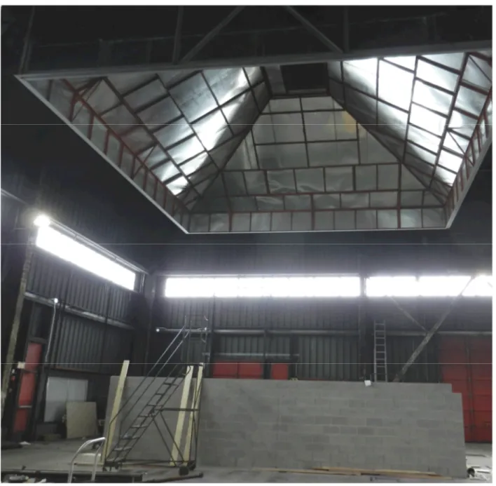
Figure 1. Photograph showing lowest (first) storey concrete block walls and exhaust hood. ...4
Figure 2. Test setup three storey elevation. ...5
Figure 3. Apartment (fire floor) layout (all measurements in m). ...12
Figure 4. Wall assemblies. ...12
Figure 5. Isometric view of CLT structural assembly. ...13
Figure 6. Fuel load layout...14
Figure 7. Location of thermocouple trees in the bedroom ( .), living room/kitchen ( ) and entryway ( ). ...20
Figure 8. Sketch showing locations of thermocouples in wall assemblies. (The locations indicated by had thermocouples located at the 0.6, 1.2 and 1.8 m heights. The locations indicated by had a single thermocouple at the 1.8 m height.) ...20
Figure 9. Sketch showing the locations of the thermocouples in the ceiling assemblies in the bedroom and living room and kitchen ( ). ...21
Figure 10. Temperatures southeast bedroom thermocouple tree. ...28
Figure 11. Temperatures southwest bedroom thermocouple tree...28
Figure 12. Temperatures northeast bedroom thermocouple tree...28
Figure 13. Temperatures northwest bedroom thermocouple tree. ...28
Figure 14. Temperatures south kitchen thermocouple tree...29
Figure 15. Temperatures entryway thermocouple tree. ...29
Figure 16. Temperatures center living room thermocouple tree. ...29
Figure 17. Temperatures north living room thermocouple tree. ...29
Figure 18. Temperatures west bedroom wall cavity (south)...45
Figure 19. Temperatures west bedroom wall cavity (center). ...45
Figure 20. Temperatures west bedroom wall cavity (north). ...45
Figure 21. Temperatures in bedroom/bathroom partition cavity...45
Figure 22. Temperatures interface CLT and gypsum board interior loadbearing wall (bedroom south). ...46
Figure 23. Temperatures interface CLT and gypsum board interior loadbearing wall (bedroom north). ...46
Figure 24. Temperatures interface CLT and gypsum board interior loadbearing wall (living room south). ...46
Figure 25. Temperatures interface CLT and gypsum board interior loadbearing wall (living room north). ...46
Figure 26. Temperatures interface CLT and gypsum board north exterior bedroom wall (east).47 Figure 27 Temperatures interface CLT and gypsum board north exterior bedroom wall (west). 47 Figure 28. Temperatures interface CLT and gypsum board north exterior living room wall (east). ...47
Figure 29. Temperatures interface CLT and gypsum board north exterior living room wall (west)...47
Figure 30. Temperatures east living room/kitchen wall cavity (south)...48
Figure 31. Temperatures east living room/kitchen wall cavity (center)...48
Figure 32. Temperatures east living room/kitchen wall cavity (north). ...48
Figure 33. Temperatures south corridor wall cavity (east). ...49
Figure 34. Temperatures south corridor wall cavity (center)...49
Figure 35. Temperatures south corridor wall cavity (west)...49
Figure 36. Temperature profiles at 1.2 m height in West bedroom wall. ...50
Figure 37. Temperature profiles at 1.8 m height in West bedroom wall. ...50
Figure 38. Temperatures unexposed side of West bedroom wall (South)...51
Figure 40. Temperatures unexposed side of West bedroom wall (North). ...51
Figure 41. Temperatures on unexposed (living room) side of living room/bedroom door...52
Figure 42. Temperatures on unexposed (corridor) side of corridor entryway door...52
Figure 43. Temperatures in joint between CLT panels in West bedroom wall. ...53
Figure 44. Temperatures gypsum board/CLT interface bedroom ceiling (south). ...61
Figure 45. Temperatures gypsum board/CLT interface bedroom ceiling (center). ...61
Figure 46. Temperatures gypsum board/CLT interface bedroom ceiling (north)...61
Figure 47. Temperatures gypsum board/CLT interface living room/kitchen ceiling (south). ...62
Figure 48. Temperatures gypsum board/CLT interface living room/kitchen ceiling (center). ...62
Figure 49. Temperatures gypsum board/CLT interface living room/kitchen ceiling (north)...62
Figure 50. Temperature profiles in ceiling/floor assembly at center of the bedroom (CLT/CBband CBb/CBfplotted versus right axis). ...63
Figure 51. Temperature profiles in joint between CLT panels in ceiling/floor above bedroom....64
Figure 52. Temperature unexposed side of ceiling floor assembly (south) above bedroom...65
Figure 53. Temperature unexposed side of ceiling floor assembly (center) above bedroom...65
Figure 54. Temperature unexposed side of ceiling floor assembly (north) above bedroom. ...65
Figure 55. Temperatures interface acoustic membrane and CLT bedroom floor (south). ...73
Figure 56. Temperatures interface acoustic membrane and CLT bedroom floor (center). ...73
Figure 57. Temperatures interface acoustic membrane and CLT bedroom floor (north)...73
Figure 58. Temperatures CLT/GB on the unexposed side of living room/kitchen floor (south)...74
Figure 59. Temperatures CLT/GB on the unexposed side of living room/kitchen floor (center). 74 Figure 60. Temperatures CLT/GB on the unexposed side of living room/kitchen floor (north). ..74
Figure 61. Temperatures CLT/gypsum board on the unexposed side of bedroom floor (south).75 Figure 62. Temperatures CLT/gypsum board on the unexposed side of bedroom floor (center). ...75
Figure 63. Temperatures CLT/gypsum board on the unexposed side of bedroom floor (north). 75 Figure 64. Temperature profiles in floor assembly at center of the bedroom (Plots CLT/GBband Unexp GBbversus right axis). ...76
Figure 65. Temperature in bedroom area highest storey...78
Figure 66. Temperatures in living room/kitchen area highest storey...78
Figure 67. Heat flux to façade. ...80
Figure 68. Heat flux from bedroom opening. ...82
Figure 69. Heat flux from living room opening. ...82
Figure 70. Volumetric and mass flow rate in exhaust duct...85
Figure 71. Temperature in exhaust duct...85
Figure 72. CO and CO2concentrations in the exhaust duct...86
Figure 73. Oxygen concentration in the exhaust duct...86
Figure 74. Heat release rate...87
Figure 75. Smoke obscuration measured in exhaust duct. ...87
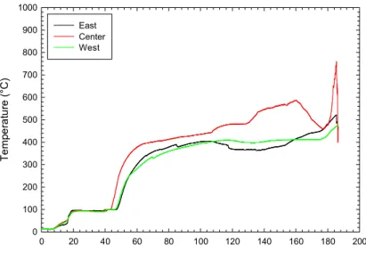
Figure 76. Maximum and average temperatures in bedroom. ...94
Figure 77. Maximum and average temperatures in living room/kitchen. ...94
Figure 78. Average temperatures at thermocouple trees in living room/kitchen (1.4 and 2.4 m heights)...95
LIST OF TABLES
Table 1. Time to reach 300C in the bedroom wall assemblies. ...42
Table 2. Time to reach 300C in the living room/kitchen wall assemblies...43
Table 3. Encapsulation times based on measurements in wall assemblies. ...44
Table 4. Time to reach 300ºC at gypsum board/CLT interface bedroom ceiling. ...59
Table 5. Time to reach 300ºC at gypsum board/CLT interface living room/kitchen ceiling. ...59
Table 6. Encapsulation times based on measurements in ceiling assembly of the middle storey (fire floor). ...60
Table 7. Time temperature reached 300ºC at interface between acoustic membrane and CLT panel...71
Table 8. Encapsulation times for floor assembly of the middle storey (fire floor)...72
Table 9. Summary of fire events regarding the bedroom...91
Table 10. Summary of fire events regarding living room and kitchen area...92
SOLUTIONS FOR MID-RISE WOOD CONSTRUCTION:
APARTMENT FIRE TEST WITH ENCAPSULATED CROSS LAMINATED TIMBER CONSTRUCTION (TEST APT-CLT)
B.C. Taber, G.D. Lougheed, J.Z. Su and N. Bénichou
1 INTRODUCTION
The acceptable solutions provided in the 2010 National Building Code (NBC) Division B [1] limits the use of combustible (wood) construction based on building height. For example, for Group C (Residential), Group D (Business and Personal Services) and Group E (Mercantile) occupancies, combustible construction can be used up to 4 storeys, and up to 2 storeys for Group A – Division 2 (Assembly) occupancies. In addition to the building height limitation, there are also building area limitations in the 2010 NBC for the use of combustible construction for these occupancies. For buildings that exceed the height and area requirements for combustible construction, the prescriptive requirements in the 2010 NBC require that noncombustible construction be used for the primary structural elements.
The prescriptive construction requirements for fire safety and protection of buildings, which are dependent upon the building size and occupancy type, are provided in Subsection 3.2.2 of the 2010 NBC. This includes the identification of the buildings for which noncombustible
construction is required. The intent of the prescriptive requirements for noncombustible
construction as they relate to the NBC fire safety/fire protection of building objectives is “to limit
the probability that combustible construction materials within a storey of a building will be involved in a fire, which could lead to the growth of fire, which could lead to the spread of fire within the storey during the time required to achieve occupant safety and for emergency responders to perform their duties, which could lead to harm to persons/damage to the building”.
The 2010 NBC defines noncombustible construction as “that type of construction in which a
degree of fire safety is attained by use of noncombustible construction materials for structural members and other building assemblies” [1]. Article 3.1.5.1 requires that a building or part of a
building required to be of noncombustible construction be constructed using noncombustible materials. The intent of this requirement, as it relates to the NBC fire safety/fire protection of building objectives, is “to limit the probability that construction materials will contribute to the
growth and spread of fire, which would lead to harm to persons/damage to the building”.
The NBC does permit, as exceptions, an extensive use of combustible materials in buildings otherwise required to have their primary structural elements to be of noncombustible
construction. The allowed materials and associated limitations are primarily provided in Articles 3.1.5.2 to 3.1.5.21. Generally, the combustible elements permitted relate to interior finishes, gypsum board, combustible roofing materials, combustible plumbing fixtures, cabling, protected insulation, flooring, combustible glazing, combustible cladding systems, non-loadbearing framing elements in partitions, stairs in dwellings, and trim and millwork, among others. Divisions B of the NBC (the “acceptable solutions” portion of the Code) generally does not permit combustible materials to be used for the primary structural elements in buildings required
to be of noncombustible construction. In the Scoping Study [
2
] for mid-rise and hybrid buildings,it was suggested that an alternative solution using wood construction may be developed to meet the intent of the prescriptive “noncombustibility” requirement for mid-rise (and taller) buildings.
As one approach, encapsulation materials could be used to protect the combustible (wood) structural materials for a period of time in order to delay the effects of the fire on the combustible structural elements, including delay of ignition. In delaying ignition, any effects of the
combustion of the combustible structural elements on the fire severity can be delayed. In some cases, and depending upon the amount of encapsulating material used (e.g. number of layers), ignition of the elements might be avoided completely. This scenario would primarily depend upon the fire event and the actual fire performance of the encapsulating materials used. A research project, Wood and Wood-Hybrid Midrise Buildings, was undertaken to develop information to be used as the basis for alternative/acceptable solutions for mid-rise construction using wood structural elements. As part of this project, four large-scale fire experiments were conducted to evaluate the fire performance of two forms of encapsulated combustible structural
wood systems, a lightweight wood-frame (LWF) system (2 experiments [
3
,4
]) and across-laminated timber (CLT) system (1 experiment). The fourth experiment [
5
] involved a teststructure constructed using a steel frame system described below. Each experiment involved construction of a test set-up of an unsprinklered full-size apartment unit, intended to represent a portion of a mid-rise (e.g. six-storey) building.
The structural elements used in the LWF system (wood stud walls and wood I-joist floors) and CLT system (3-ply wall panels and 5-ply floor panels) were all chosen on the basis of the types of construction that were currently being used in 5- and 6-storey mid-rise residential
construction being built in the province of British Columbia, where the building code had changed earlier, in 2009, to permit such mid-rise combustible construction.
The other full-scale experimental setup of an unsprinklered full-size apartment unit was built using a noncombustible lightweight steel-frame system (cold-formed steel). Other than there not being an automatic sprinkler system installed in the structure, this test setup was chosen to represent a code-conforming lightweight steel-frame system that is otherwise permitted to be
used for 6-storey residential buildings having a building area not exceeding 6 000 m2. This
resulted in the steel-frame floor assemblies, loadbearing walls, and fire separations (suite-to-suite and corridor walls/partitions) being designed and constructed to provide a 1-h fire-resistance rating. In undertaking this test of a noncombustible system, it provided the
opportunity for the fire performance of the encapsulated LWF and CLT systems to be compared with that of the lightweight steel-frame system, particularly in regards to assessing when and by how much (if at all) the ignition and burning of the wood structural elements contribute to the fire severity within the fire compartment.
This report provides the results of the experiment with an encapsulated CLT setup representing an apartment in a mid-rise (e.g. six-storey) building.
2 GENERAL TEST ARRANGEMENT
A test setup was constructed to represent a three-storey section of a building bounded on four sides (three internal walls and an exterior wall) within the lower storeys of a mid-rise (e.g. six-storey) building. The test arrangement was 8.51 m long by 6.55 m wide, which is comparable to the footprint of a one-bedroom apartment.
The test setup was located under a 10.67 m x 10.67 m hood (Figure 1), which was used to collect the hot gases and smoke produced by the fire. Instrumentation located in the ductwork, which connects the collection hood to an exhaust fan system, was used to measure the heat
release and smoke production rates produced by the fire in a simulated apartment located in the test setup.
An elevation view of the test setup is shown in Figure 2. The test arrangement was 3 storeys in height. The lowest storey was bounded by three 2.0 m high concrete block walls and one partially framed-in wall. Figure 1 shows the 8.51 m long block wall on the north side of the test arrangement. The other two block walls were located on the south side and the east end of the test setup. A concrete block wall was not included in the west end (right side of the photograph) to allow for physical access to the space below the simulated apartment.
A metal beam was mounted in the notch shown in the west end of the concrete block walls (Figure 1) to provide structural support for the middle and highest storeys of the test setup. A wood column was used to support the beam at its mid-length. A metal beam was also located across the concrete block walls near the middle of this storey to support a loadbearing wall across the middle of the floor area of each of the upper storeys.
The design and the materials for CLT test arrangement were obtained from a Canadian CLT manufacturer. The design drawings for the CLT structure are provided in Appendix A.
The middle storey of the test structure simulated a one-bedroom apartment unit with CLT structural elements used to construct the walls and floor/ceiling assemblies. One wall (north) represented a typical loadbearing exterior wall, while the other three bounding walls were designed to represent typical interior loadbearing fire separations used to separate the dwelling unit from adjacent dwelling units and the public corridor. The ceiling/floor assemblies for the test sections were also typical fire-rated assemblies. The test arrangement was designed to provide a finished floor-to-ceiling height of 2.44 m on the middle storey.
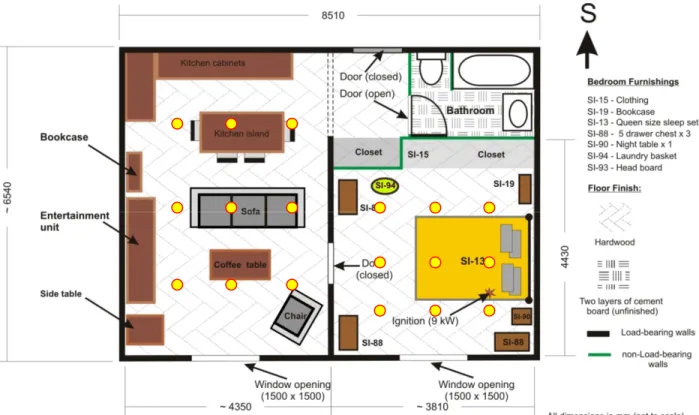
A plan view of the simulated one-bedroom apartment used for the fire test is shown in Figure 3. The test area on the middle storey (fire floor) included:
1. A 3.6 m x 3.8 m bedroom plus a closet area. No doors were mounted on the closet. The bedroom was separated from the living room by a CLT wall containing a doorway having a hollow-core wood fibre door, which was closed at the start of the test.
2. A 6.2 m x 4.25 m living room / kitchen area with the kitchen area located on the south side of the test apartment, adjacent to the simulated entryway from a public corridor. 3. An entryway with a closet. No doors were mounted on the closet. A steel door with a 45
minute fire protection rating was located in the doorway in the simulated corridor (South) wall at the entryway.
4. A bathroom adjacent to the entryway. No fixtures were located in the bathroom. The bathroom was separated from the entryway by wood stud partition containing a doorway with a hollow-core wood fibre door, which was open at the beginning of the test.
The highest storey of the test structure had the same layout as the middle storey. However, the walls were 1.83 m in height. The shorter walls were used to provide clearance between the top of the test structure and the hood.
A detailed description of the structural assemblies and the test structure is provided in the following section.
Figure 1. Photograph showing lowest (first) storey concrete block walls and exhaust hood.
Figure 2. Test setup three storey elevation.
3 STRUCTURAL ASSEMBLIES (MIDDLE STOREY)
3.1 Wall Assemblies
All the CLT structural wall assemblies were loadbearing and were constructed using 105 mm thick 3-ply CLT panels with each ply 35 mm thick. However, the method used to attach the gypsum board encapsulation differed depending on the location of the wall. Four different wall assemblies, including wood stud non-loadbearing partitions enclosing the closets and bathroom, were used in the test arrangement, as shown in Figure 4. Detailed descriptions of these wall assemblies are provided in the following sections.
3.1.1 Wall Type A
Wall Type A simulated interior loadbearing walls, with the east and west walls simulating fire separations located between adjacent dwelling units, provided with encapsulation that would result in the assemblies having more than a 90-min fire-resistance rating and the south wall simulating a fire separation located between the apartment and corridor and provided with encapsulation that would result in the assembly having more than a 90-min fire-resistance rating (Figure 4). 5.18 m 3.61 m 8.08 m Highest storey Fire floor Lowest storey
Two layers of 12.7 mm thick Type X gypsum board, oriented vertically, were attached to the CLT panels using wood strapping on the interior (fire-exposed) side of the wall.
Vertical 41 mm x 41 mm wood strapping was attached to the interior side of the walls, spaced at 600 mm O.C. The cavities formed by the wood strapping were filled with glass fibre batt
insulation. In actual practice, this lightweight wood-frame strapping would serve two purposes: 1) provide a space for electrical and plumbing services and 2) improve acoustical performance. The base layer of gypsum board was attached to the strapping using 41 mm long Type S screws spaced at 600 mm O.C. in the vertical direction.
The face layer of gypsum board was attached over the base layer, with the joints between the panels staggered from those in the base layer. The face layer was fastened to the wood strapping along its edges and its centerline, using 50 mm long Type S screws spaced at 300 mm O.C. in the vertical direction.
In real applications, the same method of attaching the gypsum board to the CLT would be used on the unexposed (non-fire) side of the CLT. However, it was expected that the fire would have little to no effect on, and not spread through or beyond, the encapsulated CLT wall during the test. Therefore, to reduce construction time, only a single layer of 12.7 mm thick Type X gypsum board, oriented vertically, was directly attached to the unexposed side of the wall assembly. The single layer of gypsum board was fastened to the CLT along its edges and in the field, using 41 mm long Type S screws spaced at 400 mm O.C. in both the vertical and horizontal directions. The joints of the gypsum board were staggered from the joints in the CLT panels. 3.1.2 Wall Type B
Wall Type B simulated an exterior loadbearing wall and was located on the north side of the test structure (Figure 4). Small CLT sections were used to connect the CLT panels on either side of the openings in the exterior wall (Figure 5).
Two layers of 12.7 mm thick Type X gypsum board, oriented vertically, were directly attached to the CLT panels on the interior side of the wall.
The base layer of gypsum board was attached using 41 mm long Type S screws spaced at 600 mm O.C. in both the vertical and horizontal directions. The joints between the panels for the base layer were staggered from the joints in the CLT panels.
The face layer of gypsum board was attached over the base layer, with the joints between the panels staggered from those in the base layer. The face layer of gypsum board was fastened using 50 mm long Type S screws spaced at 400 mm O.C. in both the vertical and horizontal directions.
A water resistant membrane (WRB) was applied to the exterior side of the CLT. Vertical wood strapping (41 mm x 41 mm) were attached over the WRB and fastened to the CLT. The
strapping was spaced at 600 mm O.C. Top and bottom plates were included at each floor level. The cavity formed by the strapping was filled with glass fibre insulation.
A single layer of 12.7 mm regular gypsum sheathing was attached to the wood strapping using 41 mm long Type S screws spaced at 300 mm O.C. in the vertical direction. The gypsum sheathing material was combustible and had a flame spread rating of 20 and a smoke development of 0.
Other fire tests were conducted within this project involving CLT exterior walls using the standard CAN/ULC-S134 fire test method [6]. Those tests showed that ordinary gypsum sheathing was sufficient to limit upward exterior flame spread when used as part of the exterior cladding system for CLT wall assemblies that included a non-loadbearing wall system
constructed on the outer face of the CLT wall using 38 mm x 144 mm studs, and having the stud cavities filled with extruded polystyrene insulation [7]. A non-combustible cladding was not used over the gypsum sheathing in the S-134 test.
The reasons for using a 41 mm x 41 mm stud wall insulated with glass fibre batt insulation, along with gypsum sheathing on the exterior face of the CLT test assembly are:
1. With the full-scale apartment testing, the objective was to investigate the impact of encapsulation of the wood structural members on fire spread within the storey of fire origin, not the potential for exterior flame spread from one storey to an upper storey in the test structure. The potential for exterior flame spread from one storey to another was examined using the CAN/ULC-S134 test method. Because no cladding was used in the simulated apartment fire test, there was the possibility of the external flames extending from the opening penetrating back through the exterior gypsum sheathing above the opening and eventually involving the wood studs and the insulation, thereby increasing the size of the fire outside the apartment, which could affect the measurements of the parameters for the fire within the apartment.
2. The non-loadbearing wood stud portion of the exterior wall was outboard of the CLT structural elements. The use of a different wall framing system with larger (deeper) studs and foam insulation was not expected to impact the test data with respect to the ability of the internal encapsulation of the CLT walls to protect the CLT from a fire originating inside the apartment.
3.1.3 Wall Type C
Non-loadbearing interior wood stud partitions were used at the south end of the bedroom to separate it from the closet in the entryway and from the bathroom (Figure 4). Similar walls were used for enclosing the bathroom. These walls were constructed using 38 mm x 89 mm wood studs, spaced 406 mm O.C. The partitions were not provided with encapsulation other than a single layer of 12.7 mm regular gypsum board, vertically oriented, which was installed on both sides of the wood stud framing, and fastened as required. The cavity spaces between the studs were filled with glass fibre batt insulation. These wall systems were identical to those used in the simulated apartment test with the lightweight wood frame test arrangement [3].
3.1.4 Wall Type D
Wall Type D was an interior loadbearing CLT wall that separated the bedroom from the living room/kitchen area. The interior loadbearing wall ran in the north-south direction for
approximately three-quarters of the full width of the test arrangement, ending at the entryway. A door opening was included in the wall with a standard interior door. This door was closed at the start of the fire.
The interior CLT wall was provided with encapsulation on both faces that would result in the assembly having more than a 90-min fire-resistance rating.
Two layers of 12.7 mm thick Type X gypsum board, oriented vertically, were directly attached to the CLT panels on both sides of the wall.
The base layer of gypsum board was fastened to the CLT along its edges and its centerline, using 41 mm long Type S screws spaced at 600 mm O.C. in both the vertical and horizontal directions. The joints between the panels for the base layer were staggered from the joints in the CLT panels.
The face layer of gypsum board was attached over the base layer, with the joints between the panels staggered from those in the base layer. The face layer of gypsum board was fastened to the CLT along its edges and in the field, using 50 mm long Type S screws spaced at
400 mm O.C. in both the vertical and horizontal directions.
3.2 Floor/ceiling Assemblies
The two floor-ceiling assemblies within the test structure were constructed using 175 mm thick 5-ply CLT panels, with each ply 35 mm thick. Each floor assembly consisted of 3 panels that ran the full-length of the test arrangement in the east-west direction (see Figure 5).
For the ceiling/floor assembly between the lowest and middle storeys, a single layer of 12.7 mm thick Type X gypsum board was directly attached to the underside of the CLT floor assembly, as the ceiling of the lowest storey. The gypsum board was fastened to the CLT along its edges and in the field, using 41 mm long Type S screws spaced at 300 mm O.C. in both directions. The gypsum board joints were not taped and they were staggered from the joints in the CLT panels. Two layers of 12.7 mm thick cement board were located on top of the CLT with limited
fastening. These two layers of cement board were used as an alternative to a concrete topping as an encapsulation material for the floor in the fire floor. This was done to speed up
construction. The joints of the base layer of cement board were staggered with the joints in the CLT panels and the joints of the face layer were staggered with the joints in the base layer. A floating hardwood floor using 17.5 mm thick hardwood flooring (nominal 19 mm) was located throughout the apartment area except the bathroom, where no finished floor was installed. Acoustic membranes were located between the CLT floor assembly and the cement board, as well as between the face layer of cement board and the hardwood floor. The acoustic
membranes used in the test assembly are identified as AM-5 and AM-6 in Reference [8]. The two products were selected based on cone calorimeter tests that indicated these products produced the highest total heat output of the acoustic membranes tested.
For the ceiling/floor assembly between the middle and highest storey, two layers of 12.7 mm thick Type X gypsum board were directly attached to the underside of the CLT floor assembly, as the ceiling of the fire floor. The base layer of gypsum board was fastened to the CLT along its edges and its centerline, using 41 mm long Type S screws spaced at 600 mm O.C. in both directions. The joints between the panels for the base layer were staggered from the joints in the CLT panels.
The face layer of gypsum board was attached over the base layer, with the joints between the panels staggered from those in the base layer. The face layer of gypsum board was fastened to
the CLT along its edges and in the field, using 50 mm long Type S screws spaced at 300 mm O.C. in both directions.
The two gypsum board layers were attached to the ceiling before the vertical wood strapping and gypsum board were attached to the wall assemblies.
On the highest storey, the top of the CLT floor panels was covered with two layers of 12.7 mm cement board with limited fastening. The joints of the base layer of cement board were
staggered with the joints in the CLT panels and the joints of the face layer were staggered with the joints in the base layer. Unlike in the fire floor, acoustic membranes and hardwood flooring were not used.
For all wall and ceiling surfaces inside the apartment on the middle storey (the fire floor), the gypsum board joints were taped and finished with joint compound.
4 LOWEST STOREY
The lowest storey of the test structure consisted of 2.0 m high concrete block walls. These walls were used to raise the test structure off the floor of the NRC research facility. This allowed access to the ceiling (underside) of the ceiling/floor assembly between the lowest and middle storeys, for construction purposes. It also provided a more representative arrangement for heat transfer through the ceiling/floor assembly with the underside of the ceiling interfacing with air rather than the concrete floor of the research facility.
The concrete block walls on the south and north sides of the test arrangement were 8.51 m long and the wall on the east end was 6.55 m long. The west end was partially framed-in and
partially left open to allow access to the space beneath the test structure.
Steel beams supported by the north and south concrete block walls were located at
approximately the length of the test assembly and at its west end. The beam at the mid-length of the test arrangement was used to support the CLT panels in the ceiling/floor assembly between the lowest and middle storeys. The two steel beams were supported at their mid-length by wood posts.
At the top of the concrete blocks walls, 38 mm x 184 mm lumber was attached to the blocks to allow the CLT wood structural elements to be fastened to the top course in the concrete block walls.
The ceiling was a single layer of 12.7 mm thick Type X gypsum board, which was directly attached to the underside of the CLT panels. The joints were not taped.
In real applications, the two layers of 12.7 mm thick gypsum board would be used on the unexposed (non-fire) side of the CLT. However, it was expected that the fire would have little to no effect on, and not spread through or beyond, the encapsulated CLT floor during the test. Therefore, to reduce construction time, only a single layer of 12.7 mm Type X gypsum board was directly attached to the unexposed side of the floor/ceiling assembly.
5 HIGHEST STOREY
The highest storey had a similar layout as the middle storey. However, the walls were 1.8 m in height. The shorter walls were used to provide clearance between the top of the test structure and the hood.
The wall assemblies were lined with a single layer of 12.7 mm Type X gypsum board directly attached to both sides of the CLT.
The wood stud partition walls separating the bedroom from the bathroom and entryway were not included in the third storey. Also, a door was not provided at the corridor entryway. An opening was located in the west wall to provide access to the third storey during construction (Figure 5). A CLT section was used to close this opening prior to the fire test.
The floor included the two layers of 12.7 mm thick cement board. The acoustic membranes and the hardwood floor were not included in the floor.
Wood I-joists were used for the ceiling assembly on the third storey. The joists spanned the width of the test arrangement. The ceiling was lined with a single layer of 12.7 mm thick Type X gypsum board, which was directly attached to the joists. The joints were not taped. A subfloor was not attached to the wood I-joists and no insulation was included in the ceiling assembly.
6 STRUCTURAL LOADING
For other than some smaller low-rise buildings, the prescriptive provisions of the NBC generally include two requirements for major structural load-bearing elements (floors, walls, roofs, etc.):
1. The elements must have sufficient structural fire resistance to limit the probability of failure or collapse during the time required for occupants to evacuate safely and emergency responders to perform their duties.
2. For larger and taller buildings, the NBC also requires the use of noncombustible construction.
Whenever the first requirement applies, and a particular level of fire-resistance rating is prescribed (e.g. 45 min, 1 h, 2 h), the level of structural fire performance (fire resistance) of a building element is addressed in the NBC by requiring testing in accordance with CAN/ULC-S101 [9]. The design methods and loadings used are those required by the NBC and the
superimposed load applied during the fire test must represent a full specified load condition or a restricted load use condition. However, these standard fire-resistance tests do not evaluate the effect or performance expected or intended by the second requirement, that is, use of
noncombustible structural elements.
The (primary) objective of the simulated apartment fire tests was to determine the fire
performance capability of the gypsum board and cement board to effectively encapsulate the combustible structural elements (and thus provide an equivalent level of fire safety to that provided by the application of the noncombustible construction requirements). In this regard, critical observations include the ability of the encapsulation to both delay (or prevent) ignition of the combustible structural elements and also limit their subsequent contribution (due to burning of the elements) to the fire severity within the fire compartment.
Given the primary objectives of the research, the standard fire resistance test, CAN/ULC-S101 was not suitable for this portion of the project. The loadbearing 3-ply CLT wall assemblies used in the test structure, with the level of encapsulation used, would be expected to demonstrate performance in the standard (CAN/ULC-S101) fire test of more than 90 min. The 5-ply CLT floor assembly, with the level of encapsulation used, would be expected to have a fire endurance period of more than 2 h.
For this simulated apartment fire test, the floor assembly of the middle storey (fire floor) was subjected to a superimposed live load arising from the presence of actual (typical) furnishings, fixtures and other contents. On the highest storey, concrete blocks were used to simulate live loads that were the same weight as the furniture and contents on the middle storey and also simulated larger items, such as the bed, in point loading. The loadbearing walls bounding the four sides and within the apartment structure (between bedroom and living room/kitchen) were subjected to the combination of the live loads on the middle and highest floors, along with the loads imposed by the self-weight (dead load) of the structure on the middle and highest storeys.
Figure 3. Apartment (fire floor) layout (all measurements in m).
Figure 4. Wall assemblies.
Wall Type A. 3-ply CLT structural elements with 41 mm x 41 mm wood strapping on the fire-exposed side, glass fiber batt insulation and 2 layers of 12.7 mm thick Type X board. Single layer 12.7 mm thick Type X gypsum board on unexposed (outer) side. Wall Type B. 3-ply CLT structural elements with 2 layers of 12.7 mm thick Type X gypsum board directly attached on the fire-exposed side. WRB used on unexposed side with a non-loadbearing 41 mm x 41 mm (2 in. x 2 in.) outboard wood stud wall with glass fibre batt insulation and 12.7 mm thick regular gypsum sheathing.
Wall Type C. 38 mm x 89 mm (2 in. x 4 in.) wood studs at 406 mm O.C.. One layer 12.7 mm thick regular gypsum board each side. Glass fibre batt insulation.
Wall Type D. 3-ply CLT structural elements with 2 layers of 12.7 mm thick Type X gypsum board directly attached
S
Wall Type C Wall Type D Kitchen Living room Bedroom Entryway Bathroom Closet ClosetFigure 5. Isometric view of CLT structural assembly.
7 FUEL LOAD
The primary fuel load present within the fire floor (middle storey) was made up of typical furniture and contents found in residential occupancies. The items used in the apartment fire tests were based on previous fire tests conducted as part of a project to develop information to be used as a basis for establishing ‘design fires’ for multi-family occupancies [10]. These fuel loads were based on actual field surveys conducted to determine fuel loads in multi-family dwelling units [11]. The layout of the fuel load in the test area is shown in Figure 6.The labels (e.g. SI-13) on the items used in the bedroom refer to single item tests conducted on the fuel item [12].
In addition to the furniture and contents, fuel was also provided by the hardwood flooring used throughout the test area except the bathroom, the kitchen cabinets and island including counter tops and by the wood framing used for the partition wall between the bedroom and the
bathroom/entrance.
Figure 6. Fuel load layout.
8 INSTRUMENTATION
Various measurement devices were used in the apartment fire test. This included
thermocouples, heat flux meters, video cameras and gas analyzers. The devices used and their location are described in the following sections.
8.1 Thermocouple Trees in the Middle Storey (Fire Floor)
Thermocouple trees were located in the bedroom, the living room/kitchen area and the entryway. For each thermocouple tree, thermocouples were located at the 0.4 m, 1.4 m and 2.4 m (25 mm below the ceiling) heights. The temperatures measured using these
thermocouples provided data on the temperature rise within the apartment.
Four thermocouple trees were located in the bedroom at the center of the room quadrants (Figure 7).
Three thermocouple trees were located in the living room and kitchen area. The trees were located along the north-south centerline of the area, with the trees located at the ¼, ½ and ¾ length of living room and kitchen area (Figure 7). A thermocouple tree was located at the center of the apartment entryway (Figure 7).
8.2 Thermocouples in Wall Assemblies
In the three simulated interior walls (Wall Type A) on the fire floor, thermocouples were located in the cavities formed by the 41 mm x 41 mm strapping used to attach the two layers of gypsum board on the exposed (fire) side of the three walls. The thermocouples were installed in the cavity space prior to the insulation and they measured the temperatures at the interface between the insulation and CLT panels.
The approximate location of thermocouples in each wall cavity area is shown in the sketch in Figure 8. The temperatures measured using these thermocouples provided data on the
temperatures in the wall assemblies, which can be used to help determine the time required for the fire to penetrate the encapsulation materials. The following lists the number and locations of the TCs in the Type A and Type C walls on the fire floor:
1. Nine thermocouples were located in the west wall (Wall Type A) of the bedroom. The thermocouples were located at the 0.6, 1.2 and 1.8 m heights at three locations along the length of the room (¼ and mid-lengths of the main bedroom area excluding the closet).
2. Three thermocouples were located in the partition wall (Wall Type C) between the bedroom and the bathroom. The thermocouples were at the 1.8 m height and were located at the ¼ and mid-widths of the bedroom. The thermocouples were located at the interface between the gypsum board and the insulation on the bedroom side of the wall. 3. Nine thermocouples were located in the east wall (Wall Type A) of the living room and
kitchen area. The thermocouples were located at the 0.6, 1.2 and 1.8 m heights at three locations along the length of the room (¼ and mid-lengths).
4. Nine thermocouples were located in the south wall (Wall Type A). The thermocouples were located at the 0.6, 1.2 and 1.8 m heights at three locations along the length of the wall (¼ and mid-lengths).
In the loadbearing CLT wall (Wall Type D) between the bedroom and living room/kitchen, the two layers of gypsum board were directly attached to the CLT and the thermocouples were located between the base layer of gypsum board and the CLT panels. Six thermocouples were located on both the bedroom and living room/kitchen sides of the wall at the 0.6, 1.2 and 1.8 m heights. The thermocouples were located at the quarter-points along the length of the bedroom wall (Figure 8).
Twelve thermocouples were located in the north wall (Wall Type B) with the two openings, which represented an exterior loadbearing CLT wall. For this wall, the two layers of gypsum board were directly attached to the interior side of the CLT panels and the thermocouples were located between the base layer of gypsum board and the CLT panels. The 12 thermocouples were located at the 0.6, 1.2 and 1.8 m heights. The thermocouples were located at the center of the wall sections on either side of the ventilation openings in the bedroom and living room
(Figure 8).
8.3 Thermocouples in Ceiling/Floor Assemblies
On the underside of the ceiling/floor assembly between the lowest and middle storeys, a single layer of gypsum board was directly attached to the CLT and thermocouples were located between the gypsum board and the CLT panels in the ceiling located below both the bedroom and the living room/kitchen areas on the fire floor.
On the underside of the ceiling/floor assembly between the middle and highest storeys, two layers of gypsum board were directly attached to the CLT and thermocouples were located between the gypsum board base layer and the CLT panels in the ceiling for the bedroom and in the living room and kitchen areas. Thermocouples were also installed between the CLT panels and the layer of acoustic membrane installed under the two layers of cement board and
hardwood flooring in the floor in the bedroom on the fire floor.
The approximate location of thermocouples in the ceiling/floor assemblies on both storeys (levels) are shown in the sketch in Figure9. The temperatures measured using these
thermocouples provided data on the temperatures in the ceiling/floor assemblies, which can be used to determine the time required for the fire to penetrate the encapsulation materials within the different rooms.
1. Nine thermocouples were located between the base layer of gypsum board and the CLT panels in the ceiling/floor assembly above the bedroom. The thermocouples were located at the quarter- and mid-widths and lengths of the bedroom area, excluding the closet.
2. Nine thermocouples were located between the single layer of gypsum board (ceiling) in the lowest storey and the CLT panels in the floor assembly below the bedroom. The thermocouples were located at the quarter- and mid-widths and lengths of the bedroom area, excluding the closet. The thermocouples were installed from the top of the floor through holes drilled in the CLT panels.
3. Nine thermocouples were located between the base layer of gypsum board and the CLT panels in the ceiling/floor assembly above the living room and kitchen. The
thermocouples were located at the quarter- and mid-widths and lengths of the kitchen and living room area.
4. Nine thermocouples were located between the single layer of gypsum board (ceiling) in the lowest (first) storey and the CLT panels in the floor assembly below the living room and kitchen. The thermocouples were located at the quarter- and mid-widths and lengths of the living room/kitchen area. The thermocouples were installed from the top of the floor through holes drilled in the CLT panels.
8.4 Surface and Interface Temperatures
There were ten thermocouples located at the mid-length of the West bedroom wall to measure the temperatures either on the surface of or at the interface between the various materials used in the construction of the CLT wall assembly. The temperatures measured using these
thermocouples provided data on the temperature profiles within the wall assembly and the time required for heat transfer through the wall assembly. These ten thermocouples were at the same location as the thermocouples located in the cavity space of the west wall of the bedroom at the mid-length of the wall, with five TCs located at both the 1.2 and 1.8 m heights (Figure 8). The locations of the thermocouples, starting in the fire area (bedroom), were as follows.
1. Exposed surface of the face layer of gypsum board.
2. Interface between the face and base gypsum board layers on the exposed (fire) side of the CLT wall assembly.
3. Interface between the base layer gypsum board and the 41 mm x 41 mm wood strapping.
4. Interface between the 41 mm x 41 mm wood strapping and the CLT panel.
5. Interface between the CLT panel and the gypsum board on the unexposed (outer) side of the wall assembly.
There were five thermocouples located at the center of the bedroom to measure the
temperature either on the surface of or at the interface between the various materials used in the construction of the CLT ceiling/floor assembly separating the middle and highest storeys. The temperatures measured using these thermocouples provided data on the temperature profiles within the ceiling/floor assembly and the time required for heat transfer through the assembly. The locations of the five thermocouples, starting in the fire area (bedroom) were as follows:
1. Exposed surface of the face layer of gypsum board.
2. Interface between the face and base gypsum board layers on the exposed (fire) side of the CLT ceiling/floor assembly.
3. Interface between the base layer of gypsum board and CLT panel.
4. Interface between the CLT panel and base layer of cement board on the unexposed (upper) side of the ceiling/floor assembly.
5. Interface between the base and face layers of cement board on the unexposed (upper) side of the CLT ceiling/floor assembly.
Thermocouples were located at the center of the bedroom to measure the temperature either on the surface of or at the interface between the various materials used in the construction of the floor/ceiling assembly separating the middle and lowest storeys. The temperatures measured using these thermocouples provided data on the temperature profiles at various locations in the floor/ceiling assembly and the time required for heat transfer through the assembly. The
locations of the thermocouples, starting in the fire area (bedroom) were as follows: 1. On the exposed side (top) of the hardwood flooring.
2. Interface between the acoustic membrane and the hardwood flooring. 3. Interface between the face layer of cement board and acoustic membrane. 4. Interface between the base and face layers of cement board.
5. Interface between the acoustic membrane and the base layer of cement board.
6. Interface between the single layer of gypsum board (ceiling) in the lowest (first) storey and CLT panels.
7. Unexposed face of single layer of gypsum board (ceiling) on the unexposed side of the CLT floor assembly.
Nine thermocouples were installed between the CLT panels and the layer of acoustic
membrane installed under the two layers of cement board and wood flooring in the floor below the bedroom. The thermocouples were located at the quarter- and mid-widths and lengths of the bedroom area, excluding the closet. In plan view, these thermocouples were at the same
location as the thermocouples in the ceiling/floor assembly shown in Figure 9.
8.5 Thermocouples in the Highest Storey
Thermocouple trees were located in the bedroom and living room and kitchen area on the highest storey. Each tree was located at the center of the respective area. The thermocouples were located at the 0.4, 1.4 m heights and 1.8 m (25 mm below the ceiling).
Nine thermocouples covered with the pads used in standard fire resistance tests [9] were located on the exposed surface (top) of the face layer of cement board in the bedroom area on the highest storey. The thermocouples were located at the quarter- and mid-widths and lengths of the bedroom area, excluding the closet. In plan view, these thermocouples were at the same
location as the thermocouples in the ceiling above the bedroom area on the fire floor, as shown in Figure 9.
8.6 Additional Thermocouples
Nine thermocouples covered with pads used in standard fire resistance tests [9] were located on the surface of the gypsum board on the unexposed (outer) side of the West bedroom wall. The thermocouples are located at the 0.6, 1.2 and 1.8 m heights at three locations along the length of the bedroom (¼ and mid-lengths of the main bedroom area excluding the closet), which represents the same elevation and location as the thermocouples in the cavity of the West bedroom wall (Figure 8).
Two thermocouples were located on both the bedroom and corridor entryway doors
approximately 50 mm below the top of the door. The thermocouples on the bedroom door were located on the living room side and the thermocouples on the entryway door were located on the unexposed (corridor) side of the door.
Thermocouples were located in the joint between CLT panels 21_15 and 21_16 in the west bedroom wall (see Figures A-5 and A-7). The two panels were at the north end and the center of the wall, respectively. The joint was approximately 2.1 m from the northwest corner of the structure. The thermocouples were located in the section of the joint that was parallel with the wall and were 0.6, 1.2 and 1.8 m above the floor.
Thermocouples were located in the joint between CLT panels 11_02 and 11_03 in the bedroom ceiling/floor assembly (see Figure A-7) just above the bedroom. The two panels were at the center and north end of the floor assembly, respectively. The joint was approximately 1.8 m from the North end of the structure. The thermocouples were located in the section of the joint that was parallel with the ceiling/floor and were at the quarter and mid-widths of the bedroom.
8.7 Heat Flux Meters.
Heat fluxes were measured at various locations exterior to the fire area. This included: 1. Two heat flux meters facing the bedroom opening with both meters centered on the
opening. The heat flux meters were located 2.4 and 4.8 m from the opening.
2. Two heat flux meters facing the living room opening with both meters centered on the opening. The heat flux meters were located 2.4 and 4.8 m from the opening.
3. Heat fluxes to the exterior wall façade were measured using heat flux meters located 3.5 m above the top of the openings in the bedroom and living room. The meters were centered on the openings. This location is consistent with the location used for
measuring heat fluxes in exterior wall fire testing in accordance with CAN/ULC S134 [6]. The heat flux meters in Items 1 and 2 were used to provide data on potential exposures from the fire to adjacent buildings. The heat flux meters located in the exterior wall façade provided data on the fire exposure to the upper storey(s) and exterior cladding from the fire plumes extending from the openings on the fire floor.
8.8 Duct Measurements
The smoke and hot gases produced by the fire was collected using a 10.67 by 10.67 m hood system mounted above the test setup (Figure 2). The hood system was connected through a duct system to an exhaust fan system.
A measuring station was setup in the duct system at which a thermocouple was used to measure the smoke temperature and a pitot tube was used to measure the pressure difference produced by the flow in the duct. These measurements were used to estimate the equivalent volumetric flow rate at standard atmospheric conditions.
In addition, smoke samples were taken from the center of the duct and were analyzed to
determine the concentrations of O2, CO and CO2. These measurements, along with the
volumetric flow rate of exhaust gases, were used to determine the heat release rate using the oxygen depletion method [13].
8.9 Video
Video cameras were mounted at various locations to provide video records for the test. This included:
1. A disposable camera was located in the bedroom, viewing the ignition area on the bed. 2. A disposable camera was mounted on the east wall of the living room, viewing the
loadbearing wall between the bedroom and living room and the hollow core door mounted in this wall.
3. A disposable camera was located in the kitchen area, viewing the entryway and bathroom area.
4. A disposable camera was located in the highest storey bedroom area.
5. Two cameras were located exterior to the test setup, viewing the fire within the apartment through the bedroom and living room openings.
In addition to the cameras installed by the laboratory, video and photographic records were also taken by the NRC videographer. Additional photographs were also taken by the project
participants and NRC staff.
8.10 Smoke Alarm
A smoke alarm was located at the center of the bedroom ceiling. Its response time was determined using video records.
Figure 7. Location of thermocouple trees in the bedroom ( .), living room/kitchen ( ) and entryway ( ).
Figure 8. Sketch showing locations of thermocouples in wall assemblies. (The locations indicated by had thermocouples located at the 0.6, 1.2 and 1.8 m heights. The locations indicated by had a single thermocouple at the 1.8 m height.)
Figure 9. Sketch showing the locations of the thermocouples in the ceiling assemblies in the bedroom and living room and kitchen ( ).
9 VENTILATION
Rough openings were used in the exterior wall to provide ventilation air for the fire. One opening was in the bedroom and the second in the living room (Figure 6). Both openings were 1.5 m x 1.5 m in size.
The edges of the openings were protected using steel sheet to limit direct attack of the fire on the framing elements. The objective of the simulated apartment fire test was to investigate the performance of the encapsulation materials for the structural elements and not the attack of the fire on the structural elements at the openings. In actual applications, the structural elements would be protected by the window frame.
The size of the openings was based on previous tests conducted as part of a fire research project to develop information to be used as a basis for establishing ‘design fires’ for multi-family residential occupancies [10]. In these tests, it was determined that this size of openings would maximize the amount of combustion and thus the fire temperatures inside the building. As a result, the fire severity and its exposure to the encapsulation materials are maximized.
Within the apartment, the hollow-core (wood fibre) door between the bedroom and living room was closed at the beginning of the test (Figure 6). A similar door used for the bathroom doorway was left open at the beginning of the test.
The 45-min fire rated steel door in the south (corridor) wall was closed throughout the test (Figure 6).
10 IGNITION SCENARIO
The bedding on the bed assembly was the first item ignited. It was ignited using a 9 kW T-burner that was positioned at a distance of 470 mm from the head of the bed (Figure 6). The same ignition scenario was used in the full-scale bedroom fire tests discussed in
11 RESULTS
Various measurement devices were used in the fire test. This included thermocouples, heat flux meters, video cameras and gas analyzers. The results of these measurements are provided in the following sections.
The ambient temperature at the start of the test was approximately 0°C. The fire floor was heated prior to the test. However, after the heaters were removed, there was cooling within the fire area. The temperatures measured within the wall and floor assemblies at the beginning of the test varied depending on the location.
A smoke alarm was located on ceiling at the center of the bedroom. It responded to the fire at 19 s.
11.1 Temperatures in Simulated Apartment
Thermocouple trees were located in the bedroom, the living room/kitchen area and the entryway. For each thermocouple tree, thermocouples were located at the 0.4 m, 1.4 m and 2.4 m (25 mm below the ceiling) heights.
11.1.1 Bedroom Temperatures
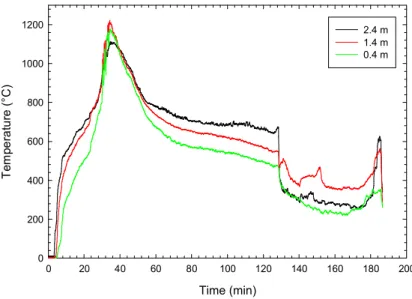
Four thermocouple trees were located in the bedroom at the southeast, southwest, northeast and northwest quarter points of the primary room area excluding the closet (Figure 7). The results measured at these locations are provided in Figure 10, Figure 11, Figure 12 and Figure 13, respectively.
There was an initial rapid increase in temperature at all heights in the bedroom with the temperature exceeding 600C near the ceiling and at the 1.4 m height within 3.0 min. The temperature increase at the 0.4 m height for the two thermocouple trees located near the ventilation opening (Figures 12 and 13) was faster than at the two locations near the partition wall, with the temperatures exceeding 600C within 3 and 5 min, respectively. These results indicate that flashover in the bedroom occurred within 3 min. The initial fire growth was consistent with a fast t-squared fire.
General observations regarding the temperatures measured at the thermocouple tree locations in the bedroom are (Note: since the total time duration for the test with the CLT structure was longer than for the tests with the lightweight frame structural assemblies, there was more variations in the temperatures measured within the bedroom and more detailed observations are provided in this report than in the reports for the other three tests):
1. Southeast thermocouple tree.
a. Initial temperature peak at 3 min with peak temperature 777C at the 1.4 m height.
b. Temperature decrease to <700C between 3 and 4 min.
c. Increase in temperature at all levels between 4 and 12 min with a maximum temperatures of approximately 1200ºC at 12 min.
d. Temperatures > 1150C until approximately 22 min.
e. Decrease in temperature between 22 and 30 min followed by temperature plateau until 40 min. There was also a temperature dip at the ceiling between 26 and 33 min.
f. Temperatures at the 1.4 m and ceiling heights comparable to approximately 40 min
g. After 40 min, temperatures gradually decreased as the fire decayed due to consumption of the combustibles in the apartment/bedroom area. Temperatures were > 800C at 1.4 m and ceiling height until 54 and 56 min, respectively. h. Dip in temperatures at 1.4 m and ceiling heights at approximately 128 min with
the failure of the steel door in the corridor wall.
i. Temperatures increased after 170 min with partial burning of CLT ceiling.
2. Southwest thermocouple tree.
a. Initial temperature peak at 3 min with peak temperature 783C at the 1.4 m height.
b. Temperature decrease to <700C at 4 min.
c. Increase in temperature at 1.4 and 2.4 m heights between 4 and 22 min. d. Increase in temperature at the 0.4 m height at approximately 15 min to
temperatures comparable to those measured at the 1.4 m and ceiling height. e. Maximum temperatures of approximately 1200ºC at the 0.4 m and 1.4 m heights
between 20 and 22 min.
f. Decrease in temperature between 22 and 30 min followed by temperature plateau until 40 min.
g. Temperatures at the 1.4 m and ceiling heights comparable to approximately 40 min. Temperatures were > 800C at 1.4 m and ceiling height until 53 and 55 min, respectively.
h. After 40 min, temperatures gradually decreased as the fire decayed due to consumption of the combustibles in the apartment/bedroom area.
i. Increase in temperature at ceiling height at approximately 96 min.
j. Dip in temperatures at 1.4 m and ceiling heights at approximately 128 min with
the failure of the steel door in the corridor wall.
k. Temperatures increased after 170 min with partial burning of CLT ceiling.
3. Northeast thermocouple tree.
a. No initial temperature peak/dip.
b. Temperatures at all heights > 950C within 5 min.
c. After 5 min, temperatures increased to 1100 - 1150C between 18 and 23 min. d. Decrease in temperature between 23 and 30 min followed by temperature
plateau until 40 min. There was also a temperature dip at the ceiling height between 26 and 33 min.
e. Temperatures at the 1.4 m and ceiling heights comparable to approximately 40 min
f. After 40 min, temperatures decreased as the fire decayed due to consumption of the combustibles in the apartment/bedroom area. Temperatures were > 800C at 1.4 m and ceiling height until 51 and 58 min, respectively.
g. Dip in temperatures at 1.4 m and ceiling heights at approximately 128 min with the failure of the steel door in the corridor wall.
h. Temperatures increased after 170 min with partial burning of CLT ceiling.
4. Northwest thermocouple tree.
a. Initial temperature peak just after 3 min, with peak temperature 948C at the 1.4 m height.
b. Temperature decrease to 803C at 4.1 min followed by increase in temperatures at all levels.
c. Temperatures at all heights exceeded 950C after 6 min with highest temperatures at 1.4 m height reaching approximately 1150C at 19 min.
d. Decrease in temperature between 24 and 30 min followed by temperature plateau until 40 min.
e. Temperatures at the 1.4 m and ceiling heights comparable to approximately 40 min. Temperatures were > 800C at 1.4 m and ceiling height until 52 and 54 min, respectively.
f. After 40 min, temperatures decreased as the fire decayed due to consumption of the combustibles in the apartment/bedroom area.
g. Rapid increase in temperature at 0.4 m height at approximately 65 min. The temperature at this height remained higher than at the other heights until approximately 144 min. (The reason for this difference in temperature at the 0.4 m height is not known. One possibility is that an object was burning near the thermocouple resulting in direct flame impingement.)
h. Dip in temperatures at 1.4 m and ceiling heights at approximately 128 min with the failure of the steel door in the corridor wall. There was a further decrease in temperatures at 144 min.
i. Temperatures increased after 170 min with partial burning of CLT ceiling.
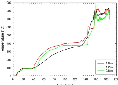
11.1.2 Living Room/Kitchen and Entryway Temperatures
Four thermocouple trees were located in the living room/kitchen area and entryway. The trees in the living room and kitchen were located along the north-south centerline of the area with the trees located at the ¼, ½ and ¾ length of living room and kitchen area (Figure 7). The results measured at South thermocouple tree, in the entryway and the mid-length and North living room trees are provided in Figure 14, Figure 15, Figure 16 and Figure 17, respectively.
Initial temperature increases were measured at the ceiling between 2 and 3 min after the fire was ignited in the bedroom. There was a faster growth in the living room area with temperatures > 600C at 4 min near the ventilation opening and at 5 min at the center of the living room. The temperatures in the kitchen and entryway were > 600C at 7 min and 14 min, respectively. These results suggest that there was localized flashover in the living room between 4 and 5 min after the fire was ignited in the bedroom. Flashover in the kitchen and entryway was at 7 and 14 min, respectively.
General observations regarding the temperatures measured at the thermocouple tree locations are (Note since the total time duration for the test with the CLT structure was longer than for the tests with the lightweight frame structural assemblies, there was more variations in the
temperatures measured within the living room/kitchen and entryway areas and more detailed observations are provided in this report than in the reports for the other three tests)::
1. North living room thermocouple tree.
a. Initial temperature increase at 3 min at ceiling.
b. Temperatures exceeded 600C at the ceiling, 1.4 and 0.4 m heights at 4, 7 and 8 min, respectively.
c. After 8 min, the temperatures measured at the ceiling and 1.4 m heights increased with a peak temperature of 1178C at 30 min at the 1.4 min height. d. General decrease in temperatures after 32 min as the fire decayed due to
consumption of the combustibles in the living room/kitchen area.
e. Temperatures at the 1.4 m and ceiling heights comparable to approximately 40 min. Temperatures were > 800C at 1.4 m and ceiling height until 57 and 63 min, respectively.